Patent application title: RADIONUCLIDE ASSAY STATION
Inventors:
Leon Carney (Knoxville, TN, US)
IPC8 Class: AB01L906FI
USPC Class:
7386491
Class name: Measuring and testing sampler, sample handling, etc. sample holder
Publication date: 2016-04-28
Patent application number: 20160114328
Abstract:
An improved dose assay station for preparing unit-dose samples of
radionuclide from a multi-dose vial is disclosed. The improved assay
station is provided an assay chamber and a radionuclide sample lifter
provided within the assay chamber. The radionuclide sample lifter is
configured for lowering a radionuclide sample container into the assay
chamber and raising the radionuclide sample container out of the assay
chamber. The radionuclide sample lifter includes a magnetically coupled
pneumatic actuator; and a carriage attached to the magnetically coupled
pneumatic actuator, the carriage being configured for holding the
radionuclide sample container, wherein the magnetically coupled pneumatic
actuator moves the carriage between a first position and a second
position within the assay chamber, wherein the first position places the
carriage near the top end of the assay chamber and the second position
places the carriage near the bottom end of the assay chamber.Claims:
1. A radionuclide dose assay station for preparing unit-dose samples of
radionuclide from a multi-dose vial comprising: an assay chamber; and a
radionuclide sample lifter provided within the assay chamber, the
radionuclide sample lifter configured for lowering a radionuclide sample
container into the assay chamber and raising the radionuclide sample
container out of the assay chamber; the radionuclide sample lifter
comprising: a magnetically coupled pneumatic actuator; and a carriage
attached to the magnetically coupled pneumatic actuator, the carriage
being configured for holding the radionuclide sample container, wherein
the magnetically coupled pneumatic actuator moves the carriage between a
first position and a second position within the assay chamber, wherein
the first position places the carriage near the top end of the assay
chamber and the second position places the carriage near the bottom end
of the assay chamber.
2. The radionuclide dose assay station of claim 1, wherein the magnetically coupled pneumatic actuator comprises a stationary part and a moving part configured to move linearly along the stationary part and the carriage is attached to the moving part.
3. The radionuclide dose assay station of claim 1, wherein the carriage is configured for holding the radionuclide sample container that is a multi-dose vial.
4. The radionuclide dose assay station of claim 1, wherein the carriage is configured for holding the radionuclide sample container that is a unit-dose syringe.
5. A radionuclide sample lifter configured for lowering a radionuclide sample container into an assay chamber and raising the radionuclide sample container out of the assay chamber, the radionuclide sample lifter comprising: a magnetically coupled pneumatic actuator; and a carriage attached to the magnetically coupled pneumatic actuator, the carriage being configured for holding the radionuclide sample container, wherein the magnetically coupled pneumatic actuator moves the carriage between a first position and a second position within the assay chamber, wherein the first position places the carriage near the top end of the assay chamber and the second position places the carriage near the bottom end of the assay chamber.
6. The radionuclide sample lifter of claim 5, wherein the magnetically coupled pneumatic actuator comprises a stationary part and a moving part configured to move linearly along the stationary part and the carriage is attached to the moving part.
7. The radionuclide sample lifter of claim 5, wherein the carriage is configured for holding the radionuclide sample container that is a multi-dose vial.
8. The radionuclide sample lifter of claim 5, wherein the carriage is configured for holding the radionuclide sample container that is a unit-dose syringe.
Description:
CROSS-REFERENCE TO RELATED APPLICATION
[0001] This application claims priority under 35 U.S.C. §119(e) from co-pending U.S. Provisional Application Ser. No. 62/067,088, filed Oct. 22, 2014, the entirety of which is hereby incorporated by reference herein.
FIELD
[0002] The present disclosure relates in general to the preparation and handling of radionuclide unit-dose samples that are used in positron emission tomography (PET).
BACKGROUND
[0003] During the preparation of unit-dose samples of radionuclides from a multi-dose vial of a PET drug, it is necessary to repeatedly place samples into a dose assay chamber for dose calibration and then subsequently remove the samples from the chamber. This process must be performed quickly and precisely while simultaneously protecting personnel and maintaining a high-quality air environment to prevent microbial contamination of the samples.
[0004] Existing technology requires either a manual placement of the samples or use of a pneumatic remote lifting device for the samples. The manual operation requires the operator to lower the samples into the assay chamber and subsequently lift the samples out of the chamber. This process necessitates unnecessary movements that makes the operation slow and introduces an increased risk of dropping the samples during placement. The existing pneumatic remote lifting devices, while an improvement over the manual method, use compressed air to provide a cushion of air underneath a platform carrying the radionuclide sample to lift or lower the platform. The platform is directly supported by the cushion of compressed air flowing upwards against the platform and, therefore, a quantity of air is always flowing upward and past the edges of the platform mechanism. Because the radionuclide samples sitting on the topside of the platform is exposed to the compressed air flowing around it, this compromises the quality of the immediate surroundings. This introduces increased risk of microbial contamination during sample handling.
[0005] Therefore, there is a need for an improved system for handling radionuclide samples that lowers the radionuclide samples into an assay chamber and then lift them out of the assay chamber that accomplishes this remotely and without compromising the quality of the radionuclide samples' immediate surroundings.
SUMMARY
[0006] According to an aspect of the present disclosure, an improved dose assay station for preparing unit-dose samples of radionuclide from a multi-dose vial is disclosed. The improved assay station is provided an assay chamber and a radionuclide sample lifter provided within the assay chamber. The radionuclide sample lifter is configured for lowering a radionuclide sample container into the assay chamber and raising the radionuclide sample container out of the assay chamber. The radionuclide sample lifter includes a magnetically coupled pneumatic actuator; and a carriage attached to the magnetically coupled pneumatic actuator, the carriage being configured for holding the radionuclide sample container, wherein the magnetically coupled pneumatic actuator moves the carriage between a first position and a second position within the assay chamber, wherein the first position places the carriage near the top end of the assay chamber and the second position places the carriage near the bottom end of the assay chamber.
[0007] According to some embodiments, a radionuclide sample lifter configured for lowering a radionuclide sample container into an assay chamber and raising the radionuclide sample container out of the assay chamber is disclosed. The radionuclide sample lifter comprises a magnetically coupled pneumatic actuator and a carriage attached to the magnetically coupled pneumatic actuator, the carriage being configured for holding the radionuclide sample container. The magnetically coupled pneumatic actuator moves the carriage between a first position and a second position within the assay chamber, wherein the first position places the carriage near the top end of the assay chamber and the second position places the carriage near the bottom end of the assay chamber.
BRIEF DESCRIPTION OF THE DRAWINGS
[0008] All drawing figures are schematic and are not necessarily to scale.
[0009] FIG. 1 shows a radionuclide dose assay station according to the present disclosure.
[0010] FIG. 2 shows the radionuclide sample lifter according to the present disclosure.
[0011] FIG. 3 shows the radionuclide sample lifter of the present disclosure in a raising mode.
[0012] FIG. 4 shows the radionuclide sample lifter of the present disclosure in a lowering mode.
[0013] FIG. 5 is a side view of the magnetically coupled pneumatic actuator according to the present disclosure carrying a multi-dose vial in its carriage.
[0014] FIG. 6 is a side view of the magnetically coupled pneumatic actuator according to the present disclosure carrying a unit-dose syringe in its carriage.
[0015] FIG. 7 is a cross-sectional view of the stationary shaft of the magnetically coupled pneumatic actuator.
DETAILED DESCRIPTION
[0016] This description of the exemplary embodiments is intended to be read in connection with the accompanying drawings, which are to be considered part of the entire written description.
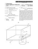
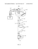
[0017] Referring to FIG. 1, according to an aspect of the present disclosure a radionuclide dose assay station 300 for preparing unit-dose samples of radionuclide is disclosed. The radionuclide dose assay station comprises an assay chamber 200 and a radionuclide sample lifter 100 provided within the assay chamber 200. The assay chamber 200 can be equipped with a well counter, such as those available from Capintec, Inc. The radionuclide dose assay station 300 also has an enclosure 310 that defines the hot cell within which the radionuclide material is handled. For example, dispensing of the radionuclide material from a multi-dose vial into single-dose syringes, for example, is conducted within the hot cell 310. The floor 320 of the hot cell 310 is provided with an opening 330 which provides access to the assay chamber 200. Various parts of the assay station 300 are made of lead in order to protect the users from radiation. In this illustration, the radionuclide sample lifter 100 is shown hanging above the opening 330 in an exploded view in order to show the radionuclide sample lifter 100. In normal operating condition for the radionuclide dose assay station 300, the radionuclide sample lifter 100 is lowered into the assay chamber 200 through the opening 330 and is positioned inside the assay chamber 200.
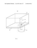
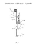
[0018] Referring to FIG. 2, the radionuclide sample lifter 100 is described in more detail. The radionuclide sample lifter 100 comprises a magnetically coupled pneumatic actuator 110 and a carriage 130 movably attached to the magnetically coupled pneumatic actuator 110. The carriage 130 is configured for holding the radionuclide sample container. The carriage 130 can include a sleeve 135 provided on the bottom side of the carriage 130. The sleeve 135 provides a protection for the radionuclide sample container being held by the carriage 130. The magnetically coupled pneumatic actuator 110 moves the carriage between a first position and a second position within the assay chamber 200. The first position is the fully raised position of the carriage 130 and places the carriage 130 near the top end of the assay chamber 200. The second position is the fully lowered position of the carriage 130 and places the carriage near the bottom end of the assay chamber 200. The radionuclide sample lifter 100 is provided inside the assay chamber 200 and, thus, by placing the radionuclide sample container inside the carriage 130, the radionuclide sample can be lowered into the assay chamber for measurement and then subsequently lifted out of the assay chamber.
[0019] In one embodiment, the magnetically coupled pneumatic actuator 110 comprises a stationary shaft 111 and an external magnetic slug 120 (see FIGS. 5, 6, and 7) that is configured to move linearly along the stationary shaft 111. The carriage 130 is coupled to the external magnetic slug 120 and thereby allowing the carriage 130 to be moved up and down along the stationary shaft 111.
[0020] Referring to FIG. 2, the radionuclide sample lifter 100 also comprises a second stationary shaft 112 for carrying compressed air. A bottom plate 150 provided at the bottom end of the radionuclide sample lifter 100. The magnetically coupled pneumatic actuator 110 is affixed to the bottom plate 150.
[0021] Provided at the top end of the radionuclide sample lifter 100 is an air manifold 116 that connects the stationary shaft 111 and the second stationary shaft 112 to a pneumatic valve switch 125 via air supply tubes 118 and 117, respectively. The pneumatic valve switch 125 delivers compressed air to the magnetically coupled pneumatic actuator 110 via the air manifold 116.
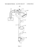
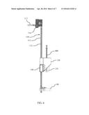
[0022] Referring to FIGS. 3 and 4, the operation of the radionuclide sample lifter 100 will be described. FIG. 3 illustrates the radionuclide sample lifter 100 in a raising mode. In the raising mode, the compressed air from the pneumatic control switch 125 is flowing via the airsupply tube 117 and through the second stationary shaft 112. The second stationary shaft 112 and the stationary shaft 111 are connected via a connecting tube 114 at the bottom end so that the compressed air from the second stationary shaft 112 is delivered to the bottom end of the stationary shaft 111 and flows upward (shown by the arrow U) through the stationary shaft 111. Thus, the compressed air is confined to the sealed pneumatic system comprises of the air supply tubes 118, 117, and the stationary shaft 111, and the second stationary shaft 112. Unlike in the conventional pneumatic radionuclide sample lifters, the radionuclide sample containers placed in the carriage 130 are never directly exposed to the compressed air.
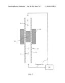
[0023] Shown in FIG. 7 is a longitudinal cross-sectional view of the stationary shaft 111 illustrating how the magnetically coupled pneumatic actuator 110 operates. The magnetically coupled pneumatic actuator 110 comprises an internal magnetic slug 122 provided inside the stationary shaft. The internal magnetic slug 122 is configured move up and down within the stationary shaft 111 by the urging of the compressed air. The direction of the internal magnetic slug 122's movement is controlled according to the direction of the compressed air flow inside the stationary shaft 111.
[0024] Thus, in order to move the internal magnetic slug 122 upward, the compressed air is delivered by the pneumatic switch 125 in a manner such that the compressed air flows upward as noted by the arrow U. On the other hand, in order to move the internal magnetic slug 122 downward, the compressed air is delivered by the pneumatic switch 125 in a manner such that the compressed air flows downward as noted by the arrow D.
[0025] The magnetically coupled pneumatic actuator 110 is provided with an external magnetic slug 120. The external magnetic slug 120 has a bore through which the stationary shaft 111 is received. The internal magnetic slug 122 and the external magnetic slug 120 are magnetic and their magnetic polarity is oriented so that the internal magnetic slug 122 and the external magnetic slug 120 magnetically couple (i.e., they attract one another). Because of this magnetic coupling between the internal magnetic slug 122 and the external magnetic slug 120, the external magnetic slug 120 can be moved along the actuator's stationary shaft 111 by driving the internal magnetic slug 122 using the compressed air within the stationary shaft 111. Thus, as the internal magnetic slug 122 moves inside the stationary shaft 111 urged by the compressed air, the external magnetic slug 120 moves along with the internal magnetic slug 122. The carriage 130 is movably attached to the magnetically coupled pneumatic actuator 110 by being attached to the external magnetic slug 120. So, when the internal magnetic slug 122 is moved by the compressed air in the stationary shaft 111, the external magnetic slug 120, and in turn, the carriage 130 move accordingly. The magnetically coupled pneumatic actuators such as the actuator 110 is readily available in the pneumatic control industry and more detailed explanation of its components is not necessary here.
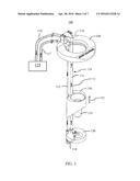
[0026] FIG. 4 illustrates the radionuclide sample lifter 100 in a lowering mode. In the lowering mode, the compressed air from the pneumatic control switch 125 is flowing via the air supply tube 118 and through the stationary shaft 111. The compressed air is moving downward, as noted by the arrow D, through the stationary shaft 111. The compressed air is moving the internal magnetic slug 122 downward, which in turn, moves the carriage 130 in downward direction DD. The compressed air then flows through the connecting tube 114, then through the second stationary shaft 112 and returns to the pneumatic control switch 125 via the tube 117.
[0027] FIG. 5 shows a side view of the magnetically coupled pneumatic actuator 110 that has a radionuclide sample container placed in the carriage 130. A portion of the carriage 130 has been cutaway to show the attachment of the carriage to the external magnetic slug 120. In this embodiment, the radionuclide sample container is a multi-dose vial 500. FIG. 6 is a side view of the magnetically coupled pneumatic actuator 110 where the radionuclide sample container is a unit-dose syringe 600. A portion of the carriage 130 has been cutaway in FIG. 6 also to show the attachment of the carriage to the external magnetic slug 120.
[0028] The radionuclide container can be a multi-dose vial 500 or a unit-dose syringe 600. The carriage 130 is configured to receive and hold either the multi-dose vial 500 or the unit-dose syringe 600. This is useful because during the preparation of the unit-dose sample of the radionuclide, the radionuclide material is dispensed into a unit-dose syringe 600 from a multi-dose vial 500 and it is optimal if both the multi-dose vial 500 and the unit-dose syringe 600 can be individually measured in the assay chamber. The multi-dose vial 500 can be placed in the assay chamber to measure how much radionuclide material is in the vial. Then, after a desired amount of radionuclide material is dispensed into a unit-dose syringe 600, the unit-dose syringe can be placed in the assay chamber to measure and confirm that a correct amount is in the unit-dose syringe. Each time the unit-dose syringe or the multi-dose vial is placed in the assay chamber, the radionuclide sample lifter 100 would simplify the operation and make it safer for the operator.
[0029] As described above, in the magnetically coupled pneumatic actuator 110 in the radionuclide sample lifter 100, the compressed air that provides the actuation is in a sealed system and the compressed air is not released into the assay chamber or the hot cell of the assay station. The actuation by the compressed air can be triggered by a foot pedal or other remote triggering device that are well known in the art. Thus, the radionuclide assay chamber of the present disclosure maintains efficient and precise sample handling while protecting the samples from potential microbial contamination due to a compromised clean air environment inside the hot cell. The quality of the compressed air used in the radionuclide assay chamber of the present disclosure is not an issue because the system does not release the compressed air into the controlled environment of the assay station.
[0030] The radionuclide sample assay chamber of the present disclosure is not limited to the specific embodiments described herein. The above description of embodiments is provided to enable any person skilled in the art to practice the disclosure. The various modifications to these embodiments will be readily apparent to those skilled in the art, and the generic principles defined herein may be applied to other embodiments without the use of inventive faculty. The present disclosure is not intended to be limited to the embodiments shown herein, but is to be accorded the widest scope consistent with the principles and novel features disclosed herein.
User Contributions:
Comment about this patent or add new information about this topic:
| People who visited this patent also read: | |
| Patent application number | Title |
|---|---|
| 20220210289 | IMAGE READING APPARATUS |
| 20220210288 | DEVICE MANAGEMENT SYSTEM AND NON-TRANSITORY COMPUTER-READABLE STORAGE MEDIUM STORING DEVICE MANAGEMENT PROGRAM |
| 20220210287 | MEDIATION DEVICE, NON-TRANSITORY COMPUTER-READABLE STORAGE MEDIUM STORING MEDIATION PROGRAM, DEVICE MANAGEMENT SYSTEM, AND NON-TRANSITORY COMPUTER-READABLE STORAGE MEDIUM STORING DEVICE MANAGEMENT PROGRAM |
| 20220210286 | READING DEVICE SETTING READING START POSITION BY READING REFERENCE HOLE HAVING L-SHAPE |
| 20220210285 | READING DEVICE, READING METHOD, AND COMPUTER-READABLE RECORDING MEDIUM |
Images included with this patent application:
 |  |
 |  |
 |  |
 |  |
| Similar patent applications: | |
| Date | Title |
|---|---|
| 2015-12-31 | Grain mass flow estimation |
| 2016-01-07 | Hydrocarbon density determination method |
| 2016-01-28 | Active monitoring of heavy weight lubrication oil |
| 2016-05-12 | Abnormality diagnosis system of air-fuel ratio sensor |
| 2015-10-15 | Flow meter device and flow rate calculation method thereof |
| New patent applications in this class: | |
| Date | Title |
|---|---|
| 2016-09-01 | Handgrip test strip ejector |
| 2016-06-16 | Pressure-rated crystal holding device for use in a high temperature crude corrosivity test |
| 2016-06-16 | Sampling device for thermal analysis |
| 2016-04-21 | Sample-tube holder for easy tube insertion and removal |
| 2016-03-17 | Self-sealing pipette septum |
| Top Inventors for class "Measuring and testing" | |
| Rank | Inventor's name |
|---|---|
| 1 | Anthony D. Kurtz |
| 2 | Alfred Rieder |
| 3 | Johannes Classen |
| 4 | Manus P. Henry |
| 5 | Heewon Jeong |