Patent application title: METHOD FOR INDEPENDENT ALIGNMENT OF AN INERTIAL UNIT FOR AN ONBOARD INSTRUMENT OF AN AIRCRAFT
Inventors:
Anne Kerbiquet (Chatellerault, FR)
Johan Bresciani (Chatellerault, FR)
Gaël Mulhaupt (Poitiers, FR)
Gaël Mulhaupt (Poitiers, FR)
Gaël Mulhaupt (Poitiers, FR)
Gaël Mulhaupt (Poitiers, FR)
Philippe Chesne (Vendome, FR)
Assignees:
THALES
IPC8 Class: AG01C2500FI
USPC Class:
73 178
Class name: Instrument proving or calibrating angle, direction, or inclination aircraft, inertial navigation, or attitude
Publication date: 2011-01-13
Patent application number: 20110005298
Inventors list |
Agents list |
Assignees list |
List by place |
Classification tree browser |
Top 100 Inventors |
Top 100 Agents |
Top 100 Assignees |
Usenet FAQ Index |
Documents |
Other FAQs |
Patent application title: METHOD FOR INDEPENDENT ALIGNMENT OF AN INERTIAL UNIT FOR AN ONBOARD INSTRUMENT OF AN AIRCRAFT
Inventors:
Philippe Chesne
Anne Kerbiquet
Johan Bresciani
Gael Mulhaupt
Agents:
BAKER & HOSTETLER LLP
Assignees:
Origin: WASHINGTON, DC US
IPC8 Class: AG01C2500FI
USPC Class:
Publication date: 01/13/2011
Patent application number: 20110005298
Abstract:
A method for independent alignment of an inertial measurement unit for a
stand-by instrument in an aircraft determining a status of the aircraft,
that is to say whether or not the aircraft is in flight, and in the case
where the aircraft is detected as being in flight, carrying out a flight
alignment, and in the case where the aircraft is not detected as being in
flight, determining a stability of the aircraft, that is to say whether
the aircraft is on the ground or at sea, and in the case where the
aircraft is detected as being on the ground, carrying out a ground
alignment, and in the case where the aircraft is detected as being at
sea, carrying out a sea alignment.Claims:
1. A method for independent alignment of an inertial measurement unit for
an onboard instrument which can equip an aircraft, the method comprising
the following steps:determining a status of whether or not the aircraft
is in flight, wherein in the case where the aircraft is detected as being
in flight, carrying out a flight alignment, and in the case where the
aircraft is not detected as being in flight;determining a stability of
the aircraft, to determine whether the aircraft is on the ground or at
sea, wherein in the case where the aircraft is detected as being on the
ground, carrying out a ground alignment, and in the case where the
aircraft is detected as being at sea carrying out a sea alignment.
2. The method according to claim 1, wherein the inertial measurement unit comprises gyrometers and wherein the flight alignment, the ground alignment and the sea alignment comprise a step of determination of an internal drift of each gyrometer.
3. The method according to claim 1, wherein the status of the aircraft is determined at least one of by an item of information coming from landing gear of the aircraft and indicating if the wheels of the landing gear are in contact with a support and by an airspeed.
4. The method according to claim 1, wherein the stability of the aircraft is determined by at least one of an accelerometer and a gyrometer.
5. The method according to claim 1, wherein the stability of the aircraft is determined by at least one of the presence or the absence of a rotation about a yaw axis of the aircraft and a translation along the yaw axis of the aircraft, a roll axis and a pitch axis of the aircraft.
6. The method according to claim 5, wherein the presence or the absence of the at least one of the rotation and the translation is determined by a predetermined threshold.
7. The method according to claim 1, wherein the flight alignment comprises the following steps:determining a time elapsed between a switching on of the onboard instrument and a switching off immediately preceding that switching on, wherein in the case in which that time is less than a predetermined duration, carrying out a short alignment, and in the contrary case, carrying out a long alignment.
8. The method according to claim 7, wherein the short alignment comprises a step comprising reusing the previously determined internal drifts of the inertial measurement unit.
9. The method according to claim 7, wherein the long alignment comprises a step of determination of minimal and maximal values of internal drifts of the inertial measurement unit and a step of precise determination of these internal drifts.
10. The method according to claim 9, wherein the step of precise determination of the internal drifts in the context of the long alignment does not take account of the instantaneous drifts of the inertial measurement unit not included between the minimal and maximal values of the internal drifts.
11. The method according to claim 7, wherein the ground alignment, the sea alignment and the long alignment each take place over a predetermined duration and in that the durations of the sea alignment and of the long alignment are greater than the duration of the ground alignment in order to be able to average the movements of the aircraft.
12. The method according to claim 1, wherein in the case where the aircraft is not detected as being in flight, the method furthermore comprises a step of determination of minimal and maximal values of internal drifts of the inertial measurement unit.
13. The method according to claim 12, wherein in the case where the aircraft is not detected as being in flight, the following steps are carried out successively:simultaneously determining the minimal and maximal values of the internal drifts of the inertial measurement unit; anddetermining the stability of the aircraft throughout the whole of the duration of determination of the minimal and maximal values of the internal drifts of the inertial measurement unit; wherein in the case where the aircraft is detected as being at sea, carrying out a sea alignment, and in the contrary case, carrying out a ground alignment.
14. The method according to claim 12, wherein, in the case where the aircraft is not detected as being in flight, the following steps are carried out successively:determining the minimal and maximal values of the internal drifts of the inertial measurement unit andsimultaneously:carrying out a sea alignment; anddetermining the stability of the aircraft throughout the whole of the duration of the ground alignment, wherein in the case where the aircraft is detected as being at sea abandoning the ground alignment, and carrying out a sea alignment.
15. The method according to claim 12, wherein, in the case where the aircraft is not detected as being in flight, the following steps are carried out successively:determining the minimal and maximal values of the internal drifts of the inertial measurement unit; andsimultaneously:carrying out a ground alignment;carrying out a sea alignment; anddetermining the stability of the aircraft throughout the whole of the duration of the ground alignment, wherein in the case where the aircraft is detected as being at sea abandoning the ground alignment, the sea alignment then being used, and in the contrary case, abandoning the sea alignment, the ground alignment then being used.
16. The method according to claim 1, wherein the onboard instrument is a stand-by instrument for generating and displaying speed, altitude and attitude information of the aircraft.
Description:
[0001]The invention relates to a method for independent alignment of an
inertial measurement unit for an onboard instrument which can equip an
aircraft. The invention relates in particular to aa method for
independent alignment of an inertial measurement unit for a stand-by
instrument generating and displaying aircraft speed, altitude and
attitude information. It is particularly useful for aligning inertial
measurement units in all possible alignment conditions. In particular,
the invention is suitable for equipping aircraft able to take off from
non-stabilized platforms, such as oil rig platforms, aircraft carriers
and helicopter carriers. It can also be applied for the alignment of
inertial measurement units equipping aircraft taking off from stable
platforms, such as a runway, insofar as the aircraft can be subjected to
movements, even when stopped, for example because of the wind or of
services around the aircraft. It can furthermore be applied for the
alignment of inertial measurement units when the aircraft is in flight.
[0002]Stand-by instruments are autonomous onboard instruments generating and displaying flight information that is essential to the pilot of an aircraft in the event of failure of primary onboard instruments. This flight information, generally obtained with lower precision than that of the primary onboard instruments, essentially relates to the speed, altitude and attitude of the aircraft. In order to guarantee the autonomy of the stand-by instruments with respect to the primary onboard instruments, the stand-by instruments must have their own sensors in order to generate and display the speed, altitude and attitude of the aircraft. In particular, the stand-by instruments usually comprise a static pressure sensor, a total pressure sensor and an inertial measurement unit.
[0003]The static and total pressure sensors are respectively connected to a static pressure port and a total pressure port located on the skin of the aircraft. The static pressure makes it possible to determine the altitude of the aircraft. The difference between the total pressure and the static pressure makes it possible to determine the speed of the aircraft with respect to the air.
[0004]The inertial measurement unit comprises for example three gyrometers and two or three accelerometers. The gyrometers measure the speeds of rotation of the sensor's reference system, in this case a system of axes related to the stand-by instrument, with respect to an inertial reference system. By integration of the rotation speeds, it is possible to know the orientation of the stand-by instrument with respect to the inertial reference system and therefore, knowing the orientation of the stand-by instrument with respect to the aircraft and the orientation of the local geographic reference system with respect to the inertial reference system, it is possible to know the orientation of the aircraft with respect to the local geographic reference system. The orientation of the aircraft with respect to the local geographic reference system, called the attitude of the aircraft, is referenced with respect to a roll axis, a pitch axis and a yaw axis and the movements about these axes are called the roll, the pitch and the yaw respectively. The accelerometers measure non-gravitational forces applied to the aircraft, from which are derived accelerations of translation of the reference system of the sensor with respect to the inertial reference system. The combination of the gyrometers and the accelerometers allows a precise determination of the attitude of the aircraft, the data provided by the accelerometers being used in preference to the data provided by the gyrometers in the static or quasi-static flight phases, and the data provided by the gyrometers being used in preference to the data provided by the accelerometers during dynamic flight phases.
[0005]During the powering up of an aircraft and in particular of a stand-by instrument, the inertial measurement unit of the stand-by instrument must be initialized in order to provide attitude information which is as reliable as possible during the flight. This initialization comprises an alignment phase notably consisting in estimating a drift of each gyrometer, that is to say a rotation speed measured by the gyrometer in question in the absence of any movement of the latter. As gyrometers are electronic sensors, their drift can differ between two switch-ons of the inertial measurement unit, to such a degree as to make any measurement carried out by these gyrometers and therefore any attitude displayed by the stand-by instrument useless. It is therefore necessary to determine the drift of the gyrometers at each switch-on. However, the switching on of the stand-by instrument can take place whilst the aircraft is standing on a stable platform, for example a runway, on an unstable platform, for example an oil rig platform, an aircraft carrier or a helicopter carrier, or even when it is in flight, after a more or less brief cut-off of the electrical power supply of the stand-by instrument. When the aircraft is standing on an unstable platform or when it is in flight, the alignment of the inertial measurement unit takes into account measurements of drifts due, not only to the intrinsic drifts of the inertial measurement unit, but also of the movements of the aircraft. In particular, the alignment can take into account movements due to wave motion when the aircraft is standing on an oil rig platform and movements due to atmospheric disturbances when it is in flight. Consequently, the alignment can be falsified by the movement of the aircraft.
[0006]In order to ensure the correct alignment of the inertial measurement unit, it is known to check for the presence or absence of movements of the inertial measurement unit by means of accelerometers of the inertial measurement unit. Throughout the whole of the duration of the alignment, the accelerometers measure the non-gravitational forces of the inertial measurement unit with respect to the inertial reference system. In the case of movement of the inertial measurement unit during the alignment, measured by the accelerometers, the stand-by instrument, at the end of the alignment, invalidates the determination of the drift of each gyrometer, displays a message indicating to the pilot the detection of movement and requesting the pilot to restart the alignment either by switching off the stand-by instrument and then switching it on again, or by pressing a button on the front face of the stand-by instrument. This restarting of the alignment is imperative insofar as the availability of the stand-by instrument, and therefore the alignment of the inertial measurement unit, is a necessary condition for the authorization of the take-off of the aircraft. Such a solution has several disadvantages. A first disadvantage is reaching the end of the alignment in order to indicate the detection of a movement during the alignment. It is therefore only at the end of the alignment of the gyrometers that the pilot knows of the invalidation of the alignment and can restart it. Consequently, the time elapsed between the detection of movement and the end of the alignment is wasted. A second disadvantage is the loss of the estimation of the drifts carried out between the start of the alignment and the detection of a movement. At the end of the invalidated alignment, the whole alignment procedure is restarted, the estimated drift risking having being falsified by the movement of the inertial measurement unit. If the alignment is restarted by a hardware reset, that is to say by switching off the stand-by instrument and then switching it on again, there is an even greater risk that the drift of the gyrometers will change, making the previous determination of the drifts obsolete. A third disadvantage is the impossibility of being able to carry out an alignment in certain situations. This can notably arise when the aircraft is started up on a moving platform. In most cases, the movement of the platform, for example due to the wave motion of the sea, cannot be prevented. The aircraft must therefore wait for the movement to stop, in this case for the wave motion to become calm, in order to be able to take off. Such an immobilization is incontestably harmful to the profitability of aircraft. Similarly, when the aircraft is in flight, the stand-by instrument risks being subjected to movements due to the piloting of the aircraft and to disturbances of the air surrounding the aircraft. Even though the pilot can limit the movements due to the piloting of the aircraft, he cannot prevent movements due to air disturbances. The alignment of the inertial measurement unit cannot therefore be carried out.
[0007]A purpose of the invention is notably to overcome all or some of the aforesaid disadvantages. For this purpose, the invention relates to a method for independent alignment of an inertial measurement unit for an onboard instrument which can equip an aircraft, characterized in that it comprises the following steps: [0008]determining a status of the aircraft, that is to say whether or not the aircraft is in flight, [0009]in the case where the aircraft is detected as being in flight: [0010]carrying out a flight alignment, [0011]in the case where the aircraft is not detected as being in flight: [0012]determining a stability of the aircraft, that is to say whether the aircraft is on the ground or at sea, [0013]in the case where the aircraft is detected as being on the ground: [0014]carrying out a ground alignment, [0015]in the case where the aircraft is detected as being at sea: [0016]carrying out a sea alignment.
[0017]The invention is notably advantageous in that it allows the alignment to be completed with the same precision whatever the conditions in which the aircraft may be, the alignment being adapted to these conditions.
[0018]The invention will be better understood and other advantages will appear on reading the detailed description of an embodiment given by way of example and with reference to the appended drawings in which:
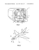
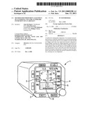
[0019]FIG. 1 shows a stand-by instrument able to equip an aircraft;
[0020]FIG. 2 shows an aircraft equipped with the stand-by instrument shown in FIG. 1, the aircraft and the stand-by instrument each having a system of axes;
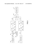
[0021]FIG. 3 is a block diagram of the means used by the stand-by instrument for the calculation and display of the attitude of the aircraft;
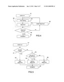
[0022]FIG. 4 shows steps used for the alignment of the stand-by instrument;
[0023]FIG. 5 shows an example of steps used according to the invention for the alignment of the stand-by instrument;
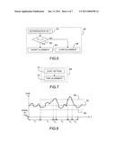
[0024]FIG. 6 shows an example of sub-steps used according to the invention for the alignment of the stand-by instrument during a flight of the aircraft;
[0025]FIG. 7 shows an example of sub-steps used according to the invention for the alignment of the stand-by instrument after a long break in the power supply during a flight of the aircraft;
[0026]FIG. 8 shows, in the form of a timing diagram, an example of alignment of the stand-by instrument during a flight of the aircraft;
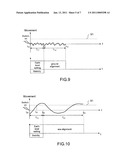
[0027]FIG. 9 shows, in the form of a timing diagram, an example of ground alignment of the stand-by instrument according to a first embodiment,
[0028]FIG. 10 shows, in the form of a timing diagram, an example of sea alignment of the stand-by instrument according to the first embodiment;
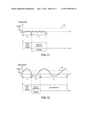
[0029]FIG. 11 shows, in the form of a timing diagram, an example of ground alignment of the stand-by instrument according to a second embodiment;
[0030]FIG. 12 shows, in the form of a timing diagram, an example of sea alignment of the stand-by instrument according to the second embodiment;
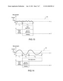
[0031]FIG. 13 shows, in the form of a timing diagram, an example of ground alignment of the stand-by instrument according to a third embodiment;
[0032]FIG. 14 shows, in the form of a timing diagram, an example of sea alignment of the stand-by instrument according to the third embodiment.
[0033]The following description is given in relation to a stand-by instrument. It is of course possible to implement the invention for any onboard instrument comprising an inertial measurement unit.
[0034]FIG. 1 shows a stand-by instrument 1 able to equip an aircraft. The stand-by instrument 1 comprises a display device 2, for example a liquid crystal display. The display device 2 displays flight information essential for the piloting of the aircraft. This information notably relates to the airspeed, the altitude and the attitude of the aircraft. The airspeed and the altitude of the aircraft are represented in the form of scrolling vertical graduated scales, one scale 3 indicating the airspeed of the aircraft and one scale 4 indicating the altitude of the aircraft. The attitude of the aircraft is symbolized by a horizontal line 5 which is mobile with respect to a fixed silhouette 6 representing the aircraft. The airspeed and altitude items of information are obtained from anemo-barometric sensors connected on the one hand to pressure pickups disposed on the skin of the aircraft and on the other hand to a computer. The anemo-barometric sensors provide a static pressure Ps and a total pressure Pt of the air surrounding the aircraft from which the computer determines the airspeed and the altitude of the aircraft. The attitude of the aircraft is obtained from an inertial measurement unit comprising gyrometers and accelerometers, as explained below. The anemo-barometric sensors, the inertial measurement unit and the computer form means of determination of the flight parameters. These determination means are independent because they are part of the stand-by instrument 1 and can operate without any other information other than that coming from the pressure sensors.
[0035]FIG. 2 shows an aircraft 20 equipped with the stand-by instrument 1 and FIG. 3 is a block diagram of the means used by the stand-by instrument 1 for the calculation and display of the attitude of the aircraft 20. The inertial measurement unit 1 generally comprises three gyrometers 30 and three accelerometers 31. The gyrometers 30 measure the angular velocities {right arrow over (Ωis)} of a reference frame Ris({right arrow over (X)}is, {right arrow over (Y)}is, {right arrow over (Z)}is) associated with the stand-by instrument 1 with respect to an inertial reference frame. For the readability of the description it will be possible to ignore the movements of the earth and to consider a local geographic reference frame, called the terrestrial reference frame Rt({right arrow over (X)}t, {right arrow over (Y)}t, {right arrow over (Z)}t), as being the inertial reference frame. For an implementation of the invention, it will however be possible to take account of the movements of the earth with respect to the inertial reference frame. As shown in FIG. 3, the angular velocities {right arrow over (Ωis)} of the inertial measurement unit are corrected by means of an internal drifts {right arrow over (dΩc)} operator 32 of the inertial measurement unit, the vector {right arrow over (dΩc)} representing the components of the internal drifts of the inertial measurement unit, for example a drift by a gyrometer 30. The internal drifts {right arrow over (dΩc)} are for example stored in a random access memory 33. Means for determining the internal drifts {right arrow over (dΩc)} will be described below. The angular velocities thus corrected and indicated {right arrow over (Ωc)} in the reference frame Rt({right arrow over (X)}t,{right arrow over (Y)}t,{right arrow over (Z)}t) are transformed in order to obtain angular velocities of {right arrow over (Ωa)} reference frame associated with the aircraft 20 and written Ra({right arrow over (X)}a,{right arrow over (Y)}a,{right arrow over (Z)}a) with respect to the reference frame Rt({right arrow over (X)}t,{right arrow over (Y)}t,{right arrow over (Z)}t). Similarly, the accelerometers 31 measure translational accelerations {right arrow over (γis)} of the reference frame Ris({right arrow over (X)}is,{right arrow over (Y)}is,{right arrow over (Z)}is) associated with the stand-by instrument 1 with respect to the terrestrial reference frame Rt({right arrow over (X)}t,{right arrow over (Y)}t,{right arrow over (Z)}t). These translational accelerations {right arrow over (γis)} are also transformed in order to obtain translational accelerations {right arrow over (γa)} of the reference frame Ra({right arrow over (X)}a,{right arrow over (Y)}a,{right arrow over (Z)}a) associated with the aircraft 20 with respect to the reference frame Rt({right arrow over (X)}t,{right arrow over (Y)}t,{right arrow over (Z)}t). The angular velocities {right arrow over (Ωa)} and the translational accelerations {right arrow over (γa)} make it possible to determine the attitude of the aircraft 20 with respect to terrestrial reference frame Rt({right arrow over (X)}t,{right arrow over (Y)}t,{right arrow over (Z)}t) by means of a computer 34 which is part of the inertial measurement unit. Advantageously, the computer 34 also carries out the transformations of angular velocities and translational accelerations. In a particular embodiment, only the translational accelerations {right arrow over (γa)} are used for the determination of the attitude of the aircraft 20 when it is in stabilized flight. Conversely, only the angular velocities {right arrow over (Ωa)} are used for the determination of the attitude of the aircraft 20 when it is in dynamic flight. Other embodiments are possible. In particular, it is possible to use a weighting of the translational accelerations {right arrow over (γa)} and of the angular velocities for the determination of the attitude of the aircraft 20, this weighting being able to vary as a function of the flight conditions. The attitude of the aircraft 20 is displayed on the display device 2 of the stand-by instrument 1.
[0036]FIG. 4 shows steps used for the initialization of a stand-by instrument 1. When the stand-by instrument 1 is switched on at step 41, a rough estimation, called level setting 42, of the internal drifts {right arrow over (dΩc)} of the inertial measurement unit is carried out. This level setting 42 makes it possible for example to determine a minimal value and a maximal value for each internal gyrometer drift. At the end of the level setting 42, a fine alignment, also called alignment 43, is carried out in order to determine precisely the internal drift of each gyrometer 30. The alignment 43 notably comprises a step of measuring the instantaneous drifts and a step of filtering these drifts in order to obtain precise values of the internal drifts {right arrow over (dΩc)}. The level setting 42 and the alignment 43 are called global alignment 40. During this global alignment 40, the accelerometers 31 monitor the movements of the inertial measurement unit. At the end of the alignment 43, a check step 44 examines if the movements detected by the accelerometers 31 have not exceeded a predefined threshold and if the internal drifts {right arrow over (dΩc)} are between the minimal and maximal values determined during the level setting 42. If such is the case, the internal drifts {right arrow over (dΩc)} are recorded in the random access memory 33 of the stand-by instrument 1. The stand-by instrument 1 is ready for the navigation 45 and displays the attitude information of the aircraft 20. In all other cases, the internal drifts {right arrow over (dΩc)} are invalidated and the global alignment 40 is restarted as indicated by the reference sign 46.
[0037]The steps used in FIG. 4 do not allow a global alignment 40 in all of the situations in which the aircraft 20 can be. In particular, when the movements are repeated, for example because the aircraft 20 is on a moving platform or because it is in flight, the global alignment 40 is always restarted and the stand-by instrument 1 remains unavailable.
[0038]The method according to the invention makes it possible to overcome this disadvantage by steps shown in FIG. 5. When the stand-by instrument 1 is switched on at step 41, a status of the aircraft 20 is determined in a step 51, that is to say whether or not the aircraft 20 is in flight. In the case in which the aircraft 20 is detected as being in flight, a flight alignment 52 is carried out. In the case in which the aircraft 20 is not detected as being in flight, a stability of the aircraft 20 is determined in a step 53, that is to say whether the aircraft 20 is on the ground or at sea. The expression "aircraft on the ground" corresponds to a situation in which the aircraft 20 is standing on a stable support, for example a runway or the roof of a building. The expression "aircraft at sea", on the other hand, corresponds to a situation in which the aircraft 20 is standing on an unstable support, for example an oil rig platform, an aircraft carrier, a helicopter carrier or any other moving platform. In the case in which the aircraft 20 is detected as being on the ground, a ground alignment 54 is carried out. In the case in which the aircraft 20 is not detected as being on the ground, that is to say if it is detected as being at sea, a sea alignment 55 is carried out. At the end of the flight alignment 52, the ground alignment 54 or the sea alignment 55, the stand-by instrument 1 can be used for the determination and the display of the attitude of the aircraft 20 as indicated by the reference sign 45.
[0039]In a particular embodiment, the flight alignment 52, the ground alignment 54 and the sea alignment 55 comprise a step of determination of the internal drifts {right arrow over (dΩc)} of the inertial measurement unit. These internal drifts {right arrow over (dΩc)} can be recorded in the random access memory 33 of the stand-by instrument 1 at the end of the flight 52, ground 54 and sea 55 alignments.
[0040]In a particular embodiment, the status of the aircraft 20 is determined by an item of information coming from landing gear of the aircraft 20 and indicating if the wheels of the landing gear are in contact with a support. The status of the aircraft 20 can also be determined by an airspeed surrounding the aircraft 20. This airspeed can be provided autonomously by anemo-barometric sensors of the inertial measurement unit. The aircraft 20 is for example considered as being in flight when the airspeed exceeds 50 knots.
[0041]In a particular embodiment, the stability of the aircraft 20 is determined by one or more accelerometers, one or more gyrometers or a combination of accelerometers and gyrometers. Advantageously, the accelerometers 31 and the gyrometers 30 of the inertial measurement unit are used.
[0042]In a particular embodiment, the stability of the aircraft 20 is determined by the presence or the absence of a rotation about a yaw axis of the aircraft 20, a translation along this yaw axis, a roll axis and/or a pitch axis of the aircraft 20 or a combination of this rotation and of these translations. These roll, pitch and yaw axes are for example the axes {right arrow over (X)}a, {right arrow over (Y)}a and {right arrow over (Z)}a respectively. The presence or the absence of the rotation and of the translations can be determined by a predefined threshold, a rotation or a translation being present when its value exceeds this predefined threshold and absent otherwise. It can also be determined by two predefined thresholds, one negative and the other positive. In this case, a rotation or a translation is present when its value is not included between these two predefined thresholds.
[0043]In a particular embodiment, shown in FIG. 6, the flight alignment 52 can be carried out differently depending on a duration T representing the time elapsed between a switching on of the stand-by instrument 1 and a switching off immediately preceding that switching on. In a step 61, the duration T is determined. In a step 62, it is determined if this duration T is less than or greater than a predetermined duration τ, for example of one or two minutes. In the case where the duration T is less than the duration τ, a short alignment 63 is carried out. In the case where the duration T is greater than or equal to the duration τ, a long alignment 64 is carried out. This embodiment makes it possible to take account of a characteristic of the gyrometers 30 according to which their internal drift can differ between two switch-ons. An internal drift difference is due, notably, to a temperature difference inside the stand-by instrument 1. Consequently, it is possible to consider that after a short interruption on the power supply of the stand-by instrument 1, the internal drifts {right arrow over (dΩc)} vary less than after a long interruption. According to this embodiment, the short alignment 63 can comprise a step consisting in reusing the previously determined internal drifts {right arrow over (dΩc)}. Advantageously, the internal drifts {right arrow over (dΩc)} are retained in the random access memory 33, the attitude of the aircraft 20 being able to be determined directly by the stand-by instrument 1 when it is switched on. Still according to this embodiment, the long alignment 64 can comprise a step of determination of minimal and maximal values for each gyrometer internal drift, called level setting 71, and a step of precise determination of the internal drifts {right arrow over (dΩc)}, called fine alignment 72. The level setting 71 can comprise a measurement of the instantaneous drifts of the gyrometers 30, a determination of a mean value for each internal drift, and a determination of minimal and maximal values for each internal drift from the corresponding mean value and predetermined intervals, the halves of these predetermined intervals being added or subtracted to or from the mean values in order to determine the minimal and maximal values respectively. Advantageously, the fine alignment 72 does not take account of the instantaneous drifts not included between the respective minimal and maximal values of the internal drifts {right arrow over (dΩc)}. This embodiment is illustrated in FIG. 8.
[0044]FIG. 8 shows a timing diagram of an example of long alignment 64 of the stand-by instrument 1. Time is represented along the horizontal axis and an instantaneous measurement of an internal gyrometer drift is represented along the vertical axis. A real value 81 of the internal drift, determined by the fine alignment 72 but unknown until the end of that fine alignment 72, is shown by a straight line. When the stand-by instrument 1 is switched on at a time t0, the level setting 71 of the inertial measurement unit is carried out over a period T1, generally of about ten seconds. This level setting 71 makes it possible to define a minimal value 82 and a maximal value 83 for the internal gyrometer drift, this drift having to be determined between these minimal and maximal values 82 and 83. At the end of the level setting 71, at a time t1, the fine alignment 72 of the inertial measurement unit is carried out over a period T2 up to a time t2 starting from which the instantaneous measurement of the internal gyrometer drift becomes greater than the maximal value 83. Throughout the whole of the duration T3, where the instantaneous measurement of the internal drift is greater than the maximal value 83, this instantaneous measurement is not taken into account for the determination of the internal drift. At a time t3, when the instantaneous measurement becomes less than the maximal value 83, the fine alignment 72 resumes over a period T4, that is to say until a time t4 where the instantaneous measurement of the internal drift again becomes greater than the maximal value 83. Throughout the whole of the duration T5 where the instantaneous measurement of the internal drift is greater that the maximal value 83, this instantaneous measurement is not taken into account for the determination of the internal drift. At a time t5, when the instantaneous measurement again becomes less than the maximal value 83, the fine alignment 72 resumes over a period T6, that is to say until a time t6 where the fine alignment 72 ends.
[0045]The same mechanism of interruption of the taking into account of the instantaneous measurement of an internal drift can be applied for all of the gyrometers 30 and, in particular, for all of their internal drifts {right arrow over (dΩc)}. In other words, this interruption makes it possible to not take into account high amplitude movements of the aircraft 20 during the alignment of its inertial measurement unit.
[0046]In a particular embodiment, the durations of the ground alignment 54, the sea alignment 55 and the long alignment 64 are predetermined durations. Advantageously, the durations of the sea alignment 55 and of the long alignment 64 are greater than the duration of the ground alignment 54. This embodiment makes it possible to average the movements of the aircraft 20 at sea or in flight over a longer duration in order to obtain precision equivalent to that of the ground alignment 54.
[0047]In a particular embodiment, in the case where the aircraft 20 is not detected as being in flight, the method according to the invention furthermore comprises a step of determination of minimal and maximal values for each internal gyrometer drift, called earth level setting. This earth level setting can be identical to the level setting 71 of the long alignment 64.
[0048]FIGS. 9 to 14 will be considered for the continuation of this description. These figures show, in the form of timing diagrams, examples of alignment of the inertial measurement unit according to different embodiments in the case where the aircraft 20 is not detected as being in flight. In each figure, an upper timing diagram represents a movement of the inertial measurement unit as a function of time t and a lower timing diagram shows the succession of the steps of the method over this same time t. The movement is for example a translation determined by an accelerometer 31. The movement can also be a rotation determined by a gyrometer 30 or a combination of translations and rotations. In each figure, a predetermined threshold 91 makes it possible to determine the presence or absence of movement of the inertial measurement unit. The figures having an odd number correspond to a situation in which the aircraft 20 is on the ground and the figures having an even number correspond to a situation where the aircraft 20 is at sea.
[0049]According to a first embodiment, illustrated by FIGS. 9 and 10, in the case where the aircraft 20 is not detected as being in flight, the following steps are carried out successively: [0050]simultaneously: [0051]carrying out the earth level setting, [0052]determining the stability of the aircraft 20 throughout the whole of the duration of the earth level setting, [0053]in the case where the aircraft 20 is detected as being at sea: [0054]carrying out a sea alignment 55, [0055]in the contrary case: [0056]carrying out a ground alignment 54.
[0057]As shown in FIG. 9, when the stand-by instrument 1 is switched on at a time t10, the earth level setting is carried out over a period T11. The stability of the aircraft 20 is determined throughout this duration T11. At the time t11, no movement having exceeded the predefined threshold 91, a ground alignment 54 is carried out over a period 12, until a time t12.
[0058]FIG. 10 illustrates this first embodiment whilst the aircraft 20 is at sea. When the stand-by instrument 1 is switched on at a time t20, the earth level setting is similarly carried out over the period T11 and the stability of the aircraft 20 is determined. At a time t21, a movement exceeds the predefined threshold 91. Consequently, at the end of the earth level setting at a time t22, a sea alignment 55 is carried out over a period T21 until a time t23.
[0059]According to a second embodiment, illustrated by FIGS. 11 and 12, in the case where the aircraft 20 is not detected as being in flight, the following steps are carried out successively: [0060]carrying out the earth level setting, [0061]simultaneously: [0062]carrying out a ground alignment 54, [0063]determining the stability of the aircraft 20 throughout the whole of the duration of the ground alignment 54, [0064]in the case where the aircraft 20 is detected as being at sea: [0065]abandoning the ground alignment 54, [0066]carrying out a sea alignment 55.
[0067]As shown in FIG. 11, when the stand-by instrument 1 is switched on, as represented by step 41, at a time t30, the earth level setting is carried out over a period T11. At the end of the earth level setting, at a time t31, a ground alignment 54 is carried out and the stability of the aircraft 20 is determined during the period T12 until the time t32, no movement having exceeded the predetermined threshold 91.
[0068]According to FIG. 12, the earth level setting is likewise carried out over the period T11 after the switching on 41 at a time t40. At the end of the earth level setting, at a time t41, a ground alignment 54 is carried out over a period T41 and the stability of the aircraft 20 is determined up to the time t42 where a movement exceeds the predetermined threshold 91. Starting from this time t42, the ground alignment 54 and the determination of the stability of the aircraft 20 are abandoned and a sea alignment 55 is carried out over a period T21 until a time t43.
[0069]According to a third embodiment, illustrated by FIGS. 13 and 14, in the case in which the aircraft 20 is not detected as being in flight, the following steps are carried out successively: [0070]carrying out the earth level setting, [0071]simultaneously: [0072]carrying out a ground alignment 54, [0073]carrying out a sea alignment 55, [0074]determining the stability of the aircraft 20 throughout the whole of the duration of the ground alignment 54, [0075]in the case where the aircraft 20 is detected as being at sea: [0076]abandoning the ground alignment 54, the sea alignment 55 then being used, [0077]in the contrary case: [0078]abandoning the sea alignment 55, the ground alignment 54 then being used.
[0079]As shown in FIG. 13, when the stand-by instrument 1 is switched on, as represented by step 41, at a time t50, the earth level setting is carried out over a period T11. At the end of this earth level setting, at a time t51, a ground alignment 54 and a sea alignment 55 are carried out simultaneously and the stability of the aircraft 20 is determined during the period T12 until a time t52, no movement having exceeded the predefined threshold 91.
[0080]According to FIG. 14, the earth level setting is likewise carried out over the period T11 after the switching on 41 at a time t60. At the end of this earth level setting, at a time t61, a ground alignment 54 and a sea alignment 55 are carried out simultaneously and the stability of the aircraft 20 is determined over a period T61 until a time t62 where a movement exceeds the predefined threshold 91. Starting from this time t62, the ground alignment 54 and the determination of the stability of the aircraft 20 are abandoned and a sea alignment 55 is carried out over a period T62 until a time t63, the sum of the periods T61 and T62 being equal to the duration T21 of the sea alignment 55.
[0081]This third embodiment makes it possible to optimize the duration of the alignment of the inertial measurement unit whilst determining the stability of the aircraft 20 during this alignment duration.
User Contributions:
comments("1"); ?> comment_form("1"); ?>Inventors list |
Agents list |
Assignees list |
List by place |
Classification tree browser |
Top 100 Inventors |
Top 100 Agents |
Top 100 Assignees |
Usenet FAQ Index |
Documents |
Other FAQs |
User Contributions:
Comment about this patent or add new information about this topic:
| People who visited this patent also read: | |
| Patent application number | Title |
|---|---|
| 20110009016 | SNAP HOUSING FOR A MODULAR CONNECTOR ASSEMBLY |
| 20110009015 | FRETTING-RESISTANT CONNECTOR AND PROCESS FOR MANUFACTURING THE SAME |
| 20110009014 | TERMINAL CONNECTOR AND ELECTRIC WIRE WITH TERMINAL CONNECTOR |
| 20110009013 | ELASTIC SHEET STRUCTURE |
| 20110009012 | Method of Forming An Electrical Connector |
Images included with this patent application:
 |  |
 |  |
 |  |
 |  |
| New patent applications in this class: | |
| Date | Title |
|---|---|
| 2013-08-22 | Method and a system for harmonizing a frame of reference of an angular positioner relative to a terrestrial frame of reference |
| 2010-06-03 | Precision approach path indicator field testing instrument |
| New patent applications from these inventors: | |
| Date | Title |
|---|---|
| 2011-02-10 | Method for stand-alone alignment of an inertial unit for an onboard instrument capable of being mounted in an aircraft, and an onboard instrument being able to use such a method |
| 2010-07-01 | System comprising two combined instruments mounted on board an aircraft and method implementing the system |
| 2010-01-21 | Method for managing the display of a rotary counter |
| Top Inventors for class "Measuring and testing" | |
| Rank | Inventor's name |
|---|---|
| 1 | Anthony D. Kurtz |
| 2 | Alfred Rieder |
| 3 | Johannes Classen |
| 4 | Manus P. Henry |
| 5 | Heewon Jeong |