Patent application title: FLUID INJECTION PORT
Inventors:
Harry Lee (Boston, MA, US)
Assignees:
Massachusetts Institute of Technology
IPC8 Class: AB01L300FI
USPC Class:
7386461
Class name: Capture device receptacle type fluid displacement
Publication date: 2009-02-12
Patent application number: 20090038417
Inventors list |
Agents list |
Assignees list |
List by place |
Classification tree browser |
Top 100 Inventors |
Top 100 Agents |
Top 100 Assignees |
Usenet FAQ Index |
Documents |
Other FAQs |
Patent application title: FLUID INJECTION PORT
Inventors:
Harry Lee
Agents:
CHOATE, HALL & STEWART LLP
Assignees:
Massachusetts Institute of Technology
Origin: BOSTON, MA US
IPC8 Class: AB01L300FI
USPC Class:
7386461
Abstract:
Fluid injection port. An elastomeric injection nipple is supported within
a compression fitting and the injection nipple includes a slit. A first
via is provided that connects the slit in the nipple to a flow channel
leading into a fluid reservoir. A venting channel is provided in fluid
communication with the fluid reservoir and also in fluid communication
with a second via. When a pipette is inserted into the slit in the
injection nipple, the nipple deforms allowing the second via to be in
fluid communication with space on either side of the pipette tip whereby
air can be discharged.Claims:
1. Fluid injection port comprising:an elastomeric injection nipple
supported within a compression fitting, the injection nipple including a
slit;a first via connecting the slit in the nipple to a flow channel
leading into a fluid reservoir;a venting channel in fluid communication
with the fluid reservoir and in fluid communication with a second
via;wherein upon insertion of a pipette tip into the slit in the
injection nipple, the nipple deforms allowing the second via to be in
fluid communication with the external environment whereby air can be
discharged.Description:
[0001]This application is related to and claims priority to U.S.
provisional application Ser. No. 60/954,417, filed Aug. 7, 2007, the
entire contents of which is incorporated herein by reference. It is noted
that certain information and/or data in the instant specification may
supersede information and/or data in the earlier application, in which
case the instant specification will control.
BACKGROUND OF THE INVENTION
[0002]Macroscopic fluidic interfaces are important for improving the usability of microfluidic devices. For example, prior art parallel integrated bioreactor arrays require two needle punctures to fill each fluidic reservoir, one for fluid injection using a syringe and another needle to vent the air displaced by the injected fluid. While suitable for internal laboratory use, such an inconvenient fluid injection procedure impedes the adoption of new bioreactor technology.
[0003]An object of the present invention is a fluid injection port that automatically vents the displaced air from a fluid reservoir and is compatible with standard laboratory pipette tips.
SUMMARY OF THE INVENTION
[0004]In one aspect, the invention is a fluid injection port including an elastomeric injection nipple supported within a compression fitting, the injection nipple including a slit therein. A first via connects the slit in the nipple to a flow channel leading into a fluid reservoir. A venting channel is in fluid communication with the fluid reservoir and also in fluid communication with a second via. Upon insertion of a pipette tip into the slit in the injection needle, the nipple deforms allowing the second via to be in fluid communication with space on either side of the pipette tip whereby air is discharged.
BRIEF DESCRIPTION OF THE DRAWING
[0005]FIG. 1A is a plan view of the fluid injection port according to one embodiment of the invention.
[0006]FIG. 1B is a cross-sectional view of an embodiment of the invention disclosed herein.
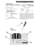
[0007]FIG. 2 is a cross-sectional view of this embodiment with a pipette inserted.
[0008]FIG. 3A is a plan view of the elastomeric nipple while compressed and sealed.
[0009]FIG. 3B is a plan view of the uncompressed elastomeric nipple.
[0010]FIG. 3C is a plan view of the compressed elastomeric nipple with pipette tip inserted.
DETAILED DESCRIPTION OF THE PREFERRED EMBODIMENT OF THE INVENTION
[0011]With reference first to FIGS. 1A, 1B, 3A, 3B, and 3C, an elastomeric nipple 10 includes a slit 12. The elastomeric nipple is supported within a compression fitting 14. The nipple 10 is disposed in a sealing relationship above a first via 16 and a second via 18. The first via 16 is in fluid communication with a flow channel 19 that extends into a fluid reservoir 20. The second via 18 is in communication with a vent channel 22 that is also in communication with the reservoir 20.
[0012]In its uncompressed and undeformed state as shown in FIG. 3B, the nipple 10, has an open slit 12. When inserted into the compression housing 14 as shown in FIGS. 1B and 3A, the nipple 10 is in a compressed but undeformed state, with the slit 12 is closed. The nipple 10 is in a sealing relation with both the first via 16 and the second via 18.
[0013]With reference now to FIGS. 2 and 3C, a pipette, for example, a 200 μL pipette 24 has been inserted through the slit 12 and into the via 16. In this configuration, the pipette 24 is sealed against the via 16 allowing fluid to be delivered through the flow channel 19 and into the fluid reservoir 20. Because of the shape of the elastomeric nipple 10, which has cutouts 25, its confinement within the compression fitting 14 leaves spaces 26 between the nipple 10 and the compression housing 14 for the nipple 10 to deform with the insertion of the pipette 24. The deformation of the nipple 10 and slit 12 when the pipette tip is inserted opens gaps 28 on either side of the pipette 24 where the slit 12 no longer seals so that the via 18 is in fluid communication with the outside air allowing air in the reservoir 20 to be discharged through vent channel 22 and the gaps 28 as fluid is delivered by the pipette into the fluid reservoir 20. The shape of the nipple 10 is chosen such that when inserted into a rectangular housing, sufficient compressive force will seal the central slit 12 closed while also allowing space 26 for the nipple 10 to expand when the pipette tip 24 is inserted. When the pipette tip 24 is removed, the slit 12 is closed, which isolates the fluid reservoir 20, and channels 19 and 24 from the external environment.
[0014]The self-sealing and self-venting injection port therefore allows easy, sterile injection of fluids into fluidic devices using standard laboratory pipettes, or automated pipetting tools. In particular, a closed chamber can be filled with a single pipette tip, without the requirement of manually introducing an opening to vent the air from the chamber as it is displaced by the injected fluid.
[0015]The self-sealing and self-venting injection port disclosed herein will be useful for the commercial development of cell culture array tools or cell-based assays requiring long-term incubation.
[0016]It is recognized that modifications and variations of the present invention will be apparent to those of ordinary skill in the art and it is intended that all such modifications and variations be included within the scope of the appended claims.
User Contributions:
comments("1"); ?> comment_form("1"); ?>Inventors list |
Agents list |
Assignees list |
List by place |
Classification tree browser |
Top 100 Inventors |
Top 100 Agents |
Top 100 Assignees |
Usenet FAQ Index |
Documents |
Other FAQs |
User Contributions:
Comment about this patent or add new information about this topic:
Images included with this patent application:
 |
| Similar patent applications: | |
| Date | Title |
|---|---|
| 2012-02-16 | Liquid volume inspection device with improved floating ball |
| 2008-10-23 | Automatic keyboard inspection apparatus |
| 2009-10-01 | Fluid transportation by a plurality of particulates |
| 2009-11-26 | Fill level measuring in mobile containers or transport silos |
| 2010-03-18 | Fluid detection with a spectrometer-on-a-chip |
| New patent applications in this class: | |
| Date | Title |
|---|---|
| 2015-12-03 | Flow timer for a sampling apparatus |
| 2009-05-07 | Liquid processing device including gas trap, and system and method |
| New patent applications from these inventors: | |
| Date | Title |
|---|---|
| 2013-08-01 | Apparatus and methods to operate a microreactor |
| 2013-08-01 | Apparatus and methods to measure optical density |
| 2011-08-11 | Method of hydrolytically stable bonding of elastomers to substrates |
| 2011-06-09 | Treatment of neurological disorders via electrical stimulation, and methods related thereto |
| 2009-09-03 | Apparatus and method for dissolved oxygen control in parallel integrated bioreactor array |
| Top Inventors for class "Measuring and testing" | |
| Rank | Inventor's name |
|---|---|
| 1 | Anthony D. Kurtz |
| 2 | Alfred Rieder |
| 3 | Johannes Classen |
| 4 | Manus P. Henry |
| 5 | Heewon Jeong |