Patent application title: PREVENTING AN OVERLOADING OF THE ELECTRONIC EVALUATION SYSTEM DUE TO VOLTAGE SPIKES IN MAGNETO-INDUCTIVE FLOWMETERS
Inventors:
Thomas Blume (Halle, DE)
Dirk Steckel (Adelebsen, DE)
Dieter Keese (Wahlsburg, DE)
Assignees:
ABB AG
IPC8 Class: AG01F160FI
USPC Class:
7386111
Class name: Volume or rate of flow by measuring electrical or magnetic properties electromagnetic induction (e.g., faraday type)
Publication date: 2008-12-18
Patent application number: 20080307892
Inventors list |
Agents list |
Assignees list |
List by place |
Classification tree browser |
Top 100 Inventors |
Top 100 Agents |
Top 100 Assignees |
Usenet FAQ Index |
Documents |
Other FAQs |
Patent application title: PREVENTING AN OVERLOADING OF THE ELECTRONIC EVALUATION SYSTEM DUE TO VOLTAGE SPIKES IN MAGNETO-INDUCTIVE FLOWMETERS
Inventors:
Thomas Blume
Dirk Steckel
Dieter Keese
Agents:
BUCHANAN, INGERSOLL & ROONEY PC
Assignees:
ABB AG
Origin: ALEXANDRIA, VA US
IPC8 Class: AG01F160FI
USPC Class:
7386111
Abstract:
The disclosure relates to a circuit arrangement for preventing overloading
of magneto-inductive flowmeters. The disclosure can protect the
amplifiers which are connected downstream thereof or the electronic
evaluation system from overloading. To this end, the signal input circuit
is provided with additional voltage-limiting diodes disposed downstream
of the impedance converters so that eventual voltage tips are prevented
during modulation in the downstream amplifiers of the evaluation
electronics.Claims:
1. A circuit arrangement for preventing an overloading of
magneto-inductive flowmeters, whereina signal input circuit is provided
with additional voltage-limiting diodes downstream of impedance
converters in such a way that possible interference spikes are prevented
from passing through to a downstream amplifier.
2. A circuit arrangement for preventing an overloading of magneto-inductive flowmeters, whereina signal input circuit is provided with additional semiconductor components and/or an amplifier circuit with a low wattage downstream of impedance converters so that possible interference spikes are prevented from passing through to a downstream amplifier.
3. A method for preventing an overloading of magneto-inductive flowmeters based on a circuit arrangement, the method comprising:Providing a signal input circuit with voltage-limiting diodes downstream of an impedance converters to prevent possible interference spikes from passing through to a downstream amplifier.
4. The circuit arrangement of claim 1, wherein the downstream amplifier is a part of an electronic evaluation system.
5. The circuit arrangement of claim 2, wherein the downstream amplifier is a part of an electronic evaluation system.
6. The method of claim 3, wherein the downstream amplifier is a part of an electronic evaluation system.
Description:
RELATED APPLICATION
[0001]This application claims priority under 35 U.S.C. §119 to German Patent Application No. 10 2005 061 836.7 filed in Germany on Dec. 23, 2005 and German Patent Application No. 10 2006 007 394.0 filed in Germany on Feb. 17, 2006, and as a continuation application under 35 U.S.C. §120 to PCT/EP2006/011991 filed as an International Application on Dec. 13, 2006 designating the U.S., the entire contents of which are hereby incorporated by reference in their entireties.
TECHNICAL FIELD
[0002]The disclosure relates to the known measuring principle used in magneto-inductive flowmeters (MIF). For example, the disclosure relates to an electronic circuit which allows interference voltage spikes Uint, which can be additively superposed on the useful signals of the signal voltage U0, and thus lead to an overloading of the electronic evaluation system, to be eliminated.
BACKGROUND INFORMATION
[0003]If an electronic evaluation system is overloaded, then the measured value cannot be determined during the overload. The current state of the art is to keep the measured value by means of downstream filter functions until interference-free signals are present once again. A disadvantage of the aforementioned method is the increased response time of the measuring system.
Signal voltage U0=kvBD+Uint
SUMMARY
[0004]Exemplary embodiments disclosed herein can damp the interference spikes occurring in the measurement procedure more strongly in order to protect the downstream amplifier.
[0005]A circuit arrangement for preventing an overloading of magneto-inductive flowmeters is disclosed, wherein the signal input circuit is provided with additional voltage-limiting diodes downstream of the impedance converters in such a way that possible interference spikes are prevented from passing through to the downstream amplifier of the electronic evaluation system.
[0006]A circuit arrangement for preventing an overloading of magneto-inductive flowmeters is disclosed, wherein the signal input circuit is provided with additional semiconductor components and/or an amplifier circuit with a low wattage downstream of the impedance converters so that possible interference spikes are prevented from passing through to the downstream amplifier of the electronic evaluation system.
[0007]In another aspect, a method is disclosed for preventing an overloading of magneto-inductive flowmeters based on a circuit arrangement. The method comprises providing a signal input circuit with voltage-limiting diodes downstream of an impedance converters to prevent possible interference spikes from passing through to a downstream amplifier.
BRIEF DESCRIPTION OF THE DRAWING
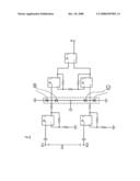
[0008]An exemplary embodiment to eliminate interference spikes superposed on the useful signal is illustrated. Specifically, a single FIGURE shows an exemplary electronic circuit diagram as described in the following text.
DETAILED DESCRIPTION
[0009]The disclosure relates to the known measuring principle used in magneto-inductive flowmeters (MIF). The physical effect used to measure the flow velocity is the law of induction. If an electrically conductive measuring material is lead through a magnetic field {right arrow over (B)}, an electric field {right arrow over (E)} which is perpendicular to the flow direction {right arrow over (v)} and the direction of the magnetic field is generated in the measuring material.
[0010]The disclosure relates to an exemplary electronic circuit embodiment which allows interference voltage spikes Uint, which can be additively superposed on the useful signals of the signal voltage U0, and thus lead to an overloading of the electronic evaluation system, to be eliminated.
[0011]It is now the idea of the disclosure to connect additional voltage-limiting diodes 10 downstream of the impedance converters in the signal input circuit 1 illustrated in the circuit diagram, in order to prevent passing possible interference spikes, and to protect the downstream amplifiers of the electronic evaluation system from overloading.
[0012]It is known to operate impedance converters with an amplification of 1. The signal voltage needs to be amplified a number of times by the subsequent amplifier stages of the electronic evaluation system in order to evaluate the very small signal voltages. Interference spikes which occur are generally much greater than the signal voltage and can thus lead to an amplifier overload.
[0013]The illustrated exemplary circuit embodiment allows elimination of the interference spikes from the amplifier stages, so that overloading, and thus interference, of the measurement operation cannot occur.
[0014]In an alternative exemplary embodiment, the voltage-limiting diodes are simply exchanged for corresponding semiconductor components and/or an amplifier circuit with a decreased wattage.
[0015]It will be appreciated by those skilled in the art that the present disclosure can be embodied in other specific forms without departing from the spirit or essential characteristics thereof. The presently disclosed embodiments are therefore considered in all respects to be illustrative and not restricted. The scope of the disclosure is indicated by the appended claims rather than the foregoing description and all changes that come within the meaning and range and equivalence thereof are intended to be embraced therein.
User Contributions:
comments("1"); ?> comment_form("1"); ?>Inventors list |
Agents list |
Assignees list |
List by place |
Classification tree browser |
Top 100 Inventors |
Top 100 Agents |
Top 100 Assignees |
Usenet FAQ Index |
Documents |
Other FAQs |
User Contributions:
Comment about this patent or add new information about this topic:
| People who visited this patent also read: | |
| Patent application number | Title |
|---|---|
| 20220141304 | Chaos Engineering in Microservices Using a Service Mesh |
| 20220141303 | SCALABLE SERVER-BASED WEB SCRIPTING WITH USER INPUT |
| 20220141302 | SYSTEMS AND METHODS FOR RESILIENT COMMUNICATION PROTOCOLS AND INTERFACES |
| 20220141301 | CONCATENATING REACTIVE PUBLISHER FOR USE WITH A MICROSERVICES OR OTHER COMPUTING ENVIRONMENT |
| 20220141300 | METHOD AND SYSTEM FOR MONITORING AN ACTIVITY OF A USER |
Images included with this patent application:
 |  |
| Similar patent applications: | |
| Date | Title |
|---|---|
| 2013-05-30 | Apparatus and method for detecting abnormality of imbalance of air-fuel ratios among cylinders |
| 2012-02-09 | Method for detecting a developing torque for a hybrid drive |
| 2012-02-02 | High accuracy battery-operated mems mass flow meter |
| 2012-03-22 | Sensing ignition by voltage monitoring |
| 2012-04-19 | Unstable electrostatic spring accelerometer |
| New patent applications in this class: | |
| Date | Title |
|---|---|
| 2016-12-29 | Fluid flow measuring device and armature comprising a fluid flow measuring device |
| 2016-06-16 | Compact microwave water-conductivity probe with integral second pressure barrier |
| 2015-12-31 | Method for operating a magnetic-inductive flow meter |
| 2015-10-15 | Rotation number measurement device, rotation number measurement method, and flow rate measurement device |
| 2015-05-21 | Flow volume detector |
| New patent applications from these inventors: | |
| Date | Title |
|---|---|
| 2009-08-13 | Method for operating a magnetic induction flowmeter |
| 2009-03-05 | Magnetic induction flowmeter having a plastic measuring tube |
| 2008-12-25 | Vortex flowmeter |
| 2008-12-18 | Method and device for functional checking of a field device before the comissioning thereof |
| Top Inventors for class "Measuring and testing" | |
| Rank | Inventor's name |
|---|---|
| 1 | Anthony D. Kurtz |
| 2 | Alfred Rieder |
| 3 | Johannes Classen |
| 4 | Manus P. Henry |
| 5 | Heewon Jeong |