Patent application title: SOLAR CELL MODULE
Inventors:
Kyung Am Kim (Seoul, KR)
IPC8 Class: AH01L31048FI
USPC Class:
136244
Class name: Batteries: thermoelectric and photoelectric photoelectric panel or array
Publication date: 2014-10-16
Patent application number: 20140305488
Abstract:
Disclosed is a solar cell module. The solar cell module includes a
substrate including at least one hole, and a first surface and a second
surface opposite to each other; a solar cell panel located on the first
surface and including a plurality of solar cells; a bus bar connected to
one of the solar cells; and a cable for outputting a current of the solar
cell panel to an outside, wherein the bus bar makes contact with the
cable through the hole.Claims:
1. A solar cell module comprising: a substrate including at least one
hole, and a first surface and a second surface opposite to each other; a
solar cell panel located on the first surface and including a plurality
of solar cells; a bus bar connected to one of the solar cells; and a
cable for outputting a current of the solar cell panel to an outside,
wherein the bus bar makes contact with the cable through the hole.
2. The solar cell module of claim 1, wherein the hole is placed at a portion corresponding to an end of the bus bar.
3. The solar cell module of claim 1, further comprising: a terminal part placed at the first surface and on the hole.
4. The solar cell module of claim 3, wherein the terminal part is placed while covering the hole.
5. The solar cell module of claim 3, wherein the terminal part is placed at an end of the bus bar.
6. The solar cell module of claim 1, wherein the cable is connected to the bus bar on the second surface through the hole.
7. The solar cell module of claim 1, wherein the cable includes at least one portion inserted into the hole.
8. The solar cell module of claim 3, wherein the cable is provided at an end thereof with an electrode that makes contact with the terminal part.
9. The solar cell module of claim 1, wherein the hole is screw-coupled with the cable.
10. The solar cell module of claim 1, wherein the cable includes a protection part and the protection part is placed on the second surface when the cable is inserted into the hole.
11. The solar cell module of claim 10, wherein the protection part surrounds the hole which is exposed toward the second surface when the cable is inserted into the hole.
12. The solar cell module of claim 1, wherein the cable is placed on a connecting part which is placed at an inside of the hole.
13. The solar cell module of claim 12, wherein the connecting part includes a solder.
14. The solar cell module of claim 12, wherein the cable is provided at an end thereof with an electrode and the connecting part makes contact with the terminal part and the electrode on two mutually different surfaces.
15. The solar cell module of claim 12, further comprising a receiving part provided on the second surface.
16. The solar cell module of claim 15, wherein the receiving part is placed while surrounding the hole.
17. The solar cell module of claim 15, wherein the receiving part is disposed at a portion to which the cable is connected.
18. The solar cell module of claim 15, wherein the cable is connected to the connecting part through the receiving part.
19. The solar cell module of claim 10, wherein a lateral width of the protection part is greater than a lateral width of the cable.
20. The solar cell module of claim 13, wherein the connecting part comprises an alloy and is formed through soldering.
Description:
TECHNICAL FIELD
[0001] The embodiment relates to a solar cell module.
BACKGROUND ART
[0002] A solar cell module to convert light energy into electrical energy through photoelectric conversion effect has been extensively known as a device to obtain non-pollution energy contributing to the conservation of global environment.
[0003] As the photoelectric conversion effect is improved, a great number of solar cell systems having a solar cell module are installed even for home use.
[0004] In order to output power generated from the solar cell module including solar cells that generate power from the light of the sun, conductors acting as positive and negative electrodes are provided in the solar cell module, and terminals of the conductors, which serve as connectors connected to a cable for outputting current to the outside, are provided outside a photovoltaic module.
[0005] In BIPV (Building Integrated Photovoltaic System) substituted for a transparent glass of a building, a junction box, which serves as an electrical connection path of the photoelectric conversion power generated from the solar cell to another electric generation system, protrudes to an outside, so that construction and treatment are difficult, and since the junction box is directly exposed to an outside, the junction box may be damaged.
[0006] In addition, the junction box protruding to the outside causes the external appearance thereof to be deteriorated and interrupts slimness of the solar cell module.
DISCLOSURE OF INVENTION
Technical Problem
[0007] The embodiment provides a solar cell module having a slim structure and representing improved reliability.
Solution to Problem
[0008] According to the embodiment, there is provided a solar cell module. The solar cell module includes a substrate including at least one hole, and a first surface and a second surface opposite to each other; a solar cell panel located on the first surface and including a plurality of solar cells; a bus bar connected to one of the solar cells; and a cable for outputting a current of the solar cell panel to an outside, wherein the bus bar makes contact with the cable through the hole.
Advantageous Effects of Invention
[0009] According to the solar cell module of the embodiment, a junction box used in the related art to connect a bus bar and a cable can be omitted. Thus, a terminal box is not exposed to an outside. Therefore, the solar cell module according to the embodiment may have improved external appearance and a slim and simple structure. In addition, the solar cell module according to the embodiment can be free in terms of construction and treatment.
BRIEF DESCRIPTION OF DRAWINGS
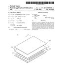
[0010] FIG. 1 is an exploded perspective view showing a solar cell module according to the first embodiment;
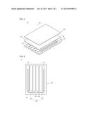
[0011] FIG. 2 is a plan view showing the solar cell panel according to the first embodiment;
[0012] FIG. 3 is a sectional view taken along line A-A' of FIG. 1;
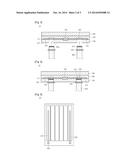
[0013] FIG. 4 is a sectional view showing a connected state of the cable in FIG. 3;
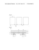
[0014] FIG. 5 is a sectional view showing a solar cell module according to the second embodiment;
[0015] FIG. 6 is a sectional view showing a state of connecting solar cell modules with each other according to the second embodiment; and
[0016] FIG. 7 is a sectional view showing a solar cell module according to the third embodiment.
MODE FOR THE INVENTION
[0017] In the description of the embodiments, it will be understood that, when a layer (or film), a region, a pattern, or a structure is referred to as being "on" or "under" another substrate, another layer (or film), another region, another pad, or another pattern, it can be "directly" or "indirectly" on the other substrate, layer (or film), region, pad, or pattern, or one or more intervening layers may also be present. Such a position of the layer has been described with reference to the drawings.
[0018] The thickness and size of each layer (or film), each region, each pattern, or each structure shown in the drawings may be exaggerated, omitted or schematically drawn for the purpose of convenience or clarity. In addition, the size of the layer (or film), the region, the pattern, or the structure does not utterly reflect an actual size.
[0019] Hereinafter, the embodiment will be described with reference to accompanying drawings in detail.
[0020] A solar cell module will be described in detail with reference to FIGS. 1 to 4. FIG. 3 is a sectional view taken along line A-A' of FIG. 1. FIG. 4 is a sectional view showing a connected state of the cable in FIG. 3. FIG. 4 is a sectional view showing a connected state of the cable in FIG. 3.
[0021] Referring to FIGS. 1 to 4, the solar cell module 10 includes a lower substrate 100, a solar cell panel 200, an upper substrate 300, a buffer sheet 400, a bus bar 500, a terminal part 600, a connector 700, and a cable 800.
[0022] The lower substrate 100 is located at the lowermost part of the solar cell module 10. The lower substrate 100 may support the solar cell panel 200.
[0023] The lower substrate 100 is transparent and has higher strength. The lower substrate 100 may include tempered glass.
[0024] Referring to FIG. 3, the lower substrate 100 includes a first surface 101 and a second surface 102 which are faced with each other.
[0025] The lower substrate 100 includes at least one hole 100a. The lower substrate 100 may include two holes 100a.
[0026] The bus bar 500 and the cable 899 may be connected to each other through the hole 100a, which will be described below.
[0027] The solar cell panel 200 is located on the lower substrate 100. The solar cell panel 200 is located on the first surface 101.
[0028] The solar cell panel 200 has a plate shape and includes a plurality of solar cells 210.
[0029] The solar cells 210 may include a CIGS-based solar cell, a silicon-based solar cell, a dye-sensitized solar cell, a group II-VI compound semiconductor solar cell, or a group III-V compound semiconductor solar cell.
[0030] In addition, the solar cells 210 may be provided on a transparent substrate such as a glass substrate.
[0031] The solar cells 210 may be arranged in the shape of a stripe. In addition, the solar cells may be arranged in various shapes such as a matrix shape.
[0032] The protection substrate 300 is provided on the solar cell panel 200. In more detail, the protection substrate 300 is provided in opposition to the solar cell panel 200.
[0033] The protection substrate 300 is transparent and has higher strength. The protection substrate 300 may include tempered glass.
[0034] The buffer sheet 400 is interposed between the protection substrate 300 and the solar cell panel 200. The buffer sheet 400 protects the solar cell panel 200 from the external physical shock. In addition, the buffer sheet 400 prevents the protection substrate 300 from colliding with the solar cell panel 200.
[0035] The buffer sheet 400 may perform an anti-reflective function so that a greater amount of light is incident onto the solar cell panel 200.
[0036] The buffer sheet 400 may include ethylenevinylacetate resin (EVA resin).
[0037] The bus bar 500 is provided on the solar cell panel 200. The bus bar 500 makes contact with two tope surfaces of the solar cell panel 200 and is electrically connected to the solar cells 210.
[0038] For example, the connection part 510 includes a first bus bar 510 and a second bus bar 520.
[0039] The first bus bar 510 makes contact with the top surface of one outermost solar cell 212 of the solar cells 210, and the second bus bar 520 makes contact with the top surface of the other outmost solar cell 211 of the solar cells 210.
[0040] The bus bar 500 may include a conductor, and may include copper (Cu).
[0041] The bus bar 500 may be connected to the cable 800 through the hole 100a.
[0042] The terminal part 600 may be placed on the first surface 101. The terminal part 600 may be placed on an upper portion of the hole 100a. That is, the terminal part 600 may be placed on the first surface 101 while covering the hole 100a.
[0043] The terminal part 600 may be placed at an end of the bus bar 500. The terminal part 600 may be connected to the bus bar 500 and the cable 800.
[0044] The cable 800 is electrically connected to the solar cell panel 200 through the bus bar 500. In other words, electrical energy generated from the solar cell panel 200 is transferred to a rectifier and/or a battery through the cable 800.
[0045] In addition, the cable 800 may be connected to an adjacent solar cell module. That is, a plurality of solar cell modules may be connected to each other through the cable 800.
[0046] The cable 800 may be connected to the bus bar 500 on the second surface 102 through the hole 100a.
[0047] At least one portion of the cable 800 may be inserted into the hole 100a.
[0048] The cable 800 may include an electrode 810 at an end of the cable 800. The electrode 810 may make contact with the terminal part 600. Thus, the cable 800 may be connected to the bus bar 500.
[0049] The cable 800 may be screw-coupled to the hole 100a. That is, a female screw may be formed at an inside wall of the hole 100a and a male screw may be formed at an outside of the cable 800. However, the embodiment is not limited thereto and the cable 800 may be combined with the hole 100a by using an adhesive. The cable 800 and the hole 100a are combined with each other through various schemes.
[0050] The cable 800 may include a protection part 820. Referring to FIG. 4, when the cable 800 is inserted into the hole 100a, the protection part 820 may be placed on the second surface 102. That is, when the cable 800 is inserted into the hole 100a, the protection part 820 may surround the hole 100a exposed toward the second surface 102.
[0051] The connector 700 may be placed on the first surface 101 of the lower surface 100. The connector 700 may include a conductor and an insulator, and may be a bypass diode.
[0052] The existing junction box for connecting the bus bar 500 and the cable 800 with each other may be omitted due to the solar cell module 10 according to the first embodiment. Thus, the solar cell module 10 according to the embodiment may have an improved external appearance and a slim and simple structure. In addition, the solar cell module 10 according to the embodiment may be free in terms of construction and treatment.
[0053] Hereinafter, a solar cell module according to the second embodiment will be described with reference to FIGS. 5 and 6. The details of the parts the same as or similar to the above-described parts will be omitted for the clear and brief description.
[0054] FIG. 5 is a sectional view showing the solar cell module according to the second embodiment. FIG. 6 is a sectional view showing a state of connecting solar cell modules with each other according to the second embodiment.
[0055] Referring to FIGS. 5 and 6, an end of the bus bar 500 included in the solar cell module 20 according to the second embodiment may be placed only at a periphery of the lower substrate 100. That is, the terminal part 600 placed at the end of the bus bar 500 may be placed at an edge portion of the lower substrate 100. Thus, the hole 100a included in the lower substrate 100 may be placed at the edge portion of the lower substrate 100. Thus, a length of the cable 800 connected into the hole 100a may be minimized. That is, referring to FIG. 6, the solar cell modules 20 may be connected to each other through the hole 100a of the edge portion while minimizing the length of the cable 800.
[0056] Hereinafter, referring to FIG. 7, a solar cell module according to the third embodiment will be described.
[0057] FIG. 7 is a sectional view showing the solar cell module according to the third embodiment.
[0058] Referring to FIG. 7, the solar cell module 30 according to the third embodiment further includes a connecting part 900 and a receiving part 850.
[0059] The connecting part 900 may be placed in the hole 100a. The connecting part 900 may include a solder. That is, the connecting part 900 may include an alloy and may be formed through soldering.
[0060] The cable 800 may be placed on the connecting part 900. In detail, the cable 800 may be connected to the connecting part 900 on the second surface 102 of the lower substrate 100.
[0061] The connecting part 900 may make contact with the terminal part 600 and the electrode 810. That is, the connecting part 900 may make contact with the terminal part 600 and the electrode 810 at two different surfaces.
[0062] The receiving part 850 may be placed on the second surface 102. The receiving part 850 may be placed while surrounding the hole 100a. The receiving part 850 may be placed at a portion to which the cable 800 is connected. The receiving part 850 may receive the cable 800. The cable 800 may be stably connected to the connecting part 900 through the receiving part 850.
[0063] Any reference in this specification to "one embodiment," "an embodiment," "example embodiment," etc., means that a particular feature, structure, or characteristic described in connection with the embodiment is included in at least one embodiment of the invention. The appearances of such phrases in various places in the specification are not necessarily all referring to the same embodiment. Further, when a particular feature, structure, or characteristic is described in connection with any embodiment, it is submitted that it is within the purview of one skilled in the art to effect such feature, structure, or characteristic in connection with other ones of the embodiments.
[0064] Although embodiments have been described with reference to a number of illustrative embodiments thereof, it should be understood that numerous other modifications and embodiments can be devised by those skilled in the art that will fall within the spirit and scope of the principles of this disclosure. More particularly, various variations and modifications are possible in the component parts and/or arrangements of the subject combination arrangement within the scope of the disclosure, the drawings and the appended claims. In addition to variations and modifications in the component parts and/or arrangements, alternative uses will also be apparent to those skilled in the art.
User Contributions:
Comment about this patent or add new information about this topic:
Images included with this patent application:
 |  |
 |  |
| Similar patent applications: | |
| Date | Title |
|---|---|
| 2013-02-21 | Solar cell module |
| 2013-03-14 | Solar cell module |
| 2013-04-04 | Solar cell module |
| 2013-04-04 | Solar cell module |
| 2013-04-25 | Solar cell module |
| New patent applications in this class: | |
| Date | Title |
|---|---|
| 2019-05-16 | Photovoltaic module |
| 2019-05-16 | Photovoltaic power circuit and resonant circuit thereof |
| 2018-01-25 | Panel driving device and heliostat |
| 2017-08-17 | Systems, circuits and methods for harvesting energy from solar cells |
| 2017-08-17 | Junction box for a photovoltaic module |
| New patent applications from these inventors: | |
| Date | Title |
|---|---|
| 2015-02-12 | Solar cell and method of fabricating the same |
| 2014-10-30 | Solar cell module and method of fabricating the same |
| 2014-01-30 | Solar cell and method for manufacturing the same |
| 2012-08-16 | Solar battery and method for manufacturing the same |
| 2012-07-19 | Solar power generation apparatus and manufacturing method thereof |
| Top Inventors for class "Batteries: thermoelectric and photoelectric" | |
| Rank | Inventor's name |
|---|---|
| 1 | Devendra K. Sadana |
| 2 | Mehrdad M. Moslehi |
| 3 | Arthur Cornfeld |
| 4 | Seung-Yeop Myong |
| 5 | Bastiaan Arie Korevaar |