Patent application title: HEAT RADIATOR
Inventors:
Tsung-Hsien Huang (I-Lan Hsien, TW)
IPC8 Class: AF28F306FI
USPC Class:
165185
Class name: Heat exchange heat transmitter
Publication date: 2013-08-15
Patent application number: 20130206381
Abstract:
A heat radiator includes a base and heat radiating fins. The base has a
surface formed with grooves for insertion of the heat radiating fins.
Each heat radiating fin has a bent portion at one end thereof. The bent
portion has spaced protrusions thereon. The bent portion is inserted and
embedded in the groove of the base. Then, a press head is aligned with
the bent portion for pressing. The press head has an inclined surface to
cover the bent portion and a side wall of the groove. After pressing, the
bent portion is deformed and enlarged to engage with the groove. The side
wall of the groove is compressed by the inclined surface of the press
head to be shifted and deformed. The deformed side wall holds against the
bent portion, so that the heat radiating fins and the base are connected.Claims:
1. A heat radiator comprising a base and a plurality of heat radiating
fins, and characterized by: the base having a surface formed with a
plurality of grooves for insertion of the plurality of heat radiating
fins; each of the plurality of heat radiating fins having a bent portion
at an insertion end thereof, the bent portion being embedded in a related
groove of the base; the embedded bent portion of each heat radiating fin
having been pressed by a press head aligned with the embedded portion
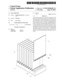
after insertion of the bent portion in the related groove of the base,
the press head having an inclined surface to cover the bent portion and a
side wall of the related groove, whereby the bent portion is deformed and
enlarged in the related groove to engage with the related groove, and the
side wall of the related groove is compressed by the inclined surface of
the press head to be shifted and deformed, so that the deformed side wall
holds against the bent portion to connect the heat radiating fins with
the base.
2. The heat radiator as claimed in claim 1, wherein the bent portion of each heat radiating fin has a plurality of spaced protrusions thereon and the deformed side wall of the related groove holds against the protrusions of the bent portion, so that the heat radiating fins are engaged in the grooves.
3. The heat radiator as claimed in claim 2, wherein a thickness of the bent portion of each heat radiating fin plus a width of the protrusions equals a width of each groove.
4. The heat radiator as claimed in claim 2, wherein the protrusions of each heat radiating fin incline upward.
5. The heat radiator as claimed in claim 1, wherein a bottom surface of the base is formed with at least one engaging groove for engagement of a conductive pipe and the conductive pipe has a flat bottom surface exposed and connected to the bottom surface of the base.
6. The heat radiator as claimed in claim 5, wherein the conductive pipe is bent to penetrate the plurality of the heat radiating fins.
7. The heat radiator as claimed in claim 1, wherein the base has a circular shape which has the plurality of grooves formed around a circumferential wall thereof for insertion of the plurality of heat radiating fins.
8. A method of making a heat radiator, comprising the steps of: providing a base having a surface formed with a plurality of grooves; providing a plurality of heat radiating fins, each heat radiating fin having a bent portion at a lower end thereof; inserting the plurality of heat radiating fins into the plurality of grooves of the base, respectively, so that the bent portion of each heat radiating fin is embedded in one of the grooves; and pressing the bent portion of each heat radiating fin and a side wall of the groove in which the bent portion is embedded using a press head, wherein the press head has an inclined surface to cover the bent portion of the heat radiating fin and the groove, whereby the bent portion is deformed and enlarged in the groove to engage with the groove, and the side wall of the groove is compressed by the inclined surface of the press head to be shifted and deformed, so that the deformed side wall holds against the bent portion to hold the heat radiating fin in the groove.
9. The method of making a heat radiator as claimed in claim 8, wherein the bent portion of each heat radiating fin has a plurality of spaced protrusions thereon and the deformed side wall of the related groove holds against the protrusions of the bent portion.
10. The method of making a heat radiator as claimed in claim 9, wherein the bent portion and the protrusions of each heat radiating fin has a combined thickness equal to the width of each groove.
11. The method of making a heat radiator as claimed in claim 9, wherein the protrusions of each heat radiating fin incline upward.
12. The method of making a heat radiator as claimed in claim 8, wherein the base has a circular shape which has the plurality of grooves formed around a circumferential wall thereof for insertion of the plurality of heat radiating fins.
Description:
BACKGROUND OF THE INVENTION
[0001] (a) Field of the Invention
[0002] The present invention relates to a heat radiator and more particularly to a heat radiator with heat radiating fins which are connected by pressing.
[0003] (b) Description of the Prior Art
[0004] A conventional heat radiator comprises a base and heat radiating fins which are connected by welding or pressing. The heat radiating fins are first inserted into grooves or a clamping seat of the base and then pressed by a press head, so that the heat radiating fins are coupled to the grooves or the clamping seat of the base, such as U.S. Pat. No. 5,014,776. The two side walls of the grooves are compressed and deformed to clamp the heat radiating fins to achieve connection of the heat radiating fins and the base.
[0005] The aforesaid patent uses the two compressed and deformed side walls of the grooves to clamp the roots of the heat radiating fins. The clamping force concentrates on the two sides of the grooves so the clamping effect is not good and the connection is unstable. The heat radiating fins may not be at the same height and they may shake to disengage from the base.
[0006] Accordingly, the present invention intends to provide a heat radiator for eliminate the shortcomings mentioned above.
SUMMARY OF THE INVENTION
[0007] The primary object of the present invention is to provide a heat radiator which comprises a base and a plurality of heat radiating fins. The base has a surface formed with a plurality of grooves for insertion of the plurality of heat radiating fins. Each heat radiating fin has a bent portion at an insertion end thereof. The bent portion is embedded in a related groove of the base. After the bent portion of each heat radiating fin is inserted into the related groove of the base, a press head is aligned with the embedded bent portion for pressing. The press head has an inclined surface to cover the bent portion and a side wall of the related groove. After pressing, the bent portion is deformed and enlarged in the related groove to engage with the related groove. The side wall of the related groove is compressed by the inclined surface of the press head to be shifted and deformed. The deformed side wall holds against the bent portion, so that the heat radiating fins and the base are firmly connected. The heat radiating fins won't shake to disengage from the base.
[0008] Another object of the present invention is to provide a heat radiator, wherein the bent portion has a plurality of spaced protrusions which are formed by extrusion. The protrusions of each heat radiating fin incline upward. After being pressed by the press head, the deformed side wall extends outward to press the protrusions of the bent portion. The other part of the bent portion is compressed and deformed to fill up the related groove of the base, such that the heat radiating fins are stably connected to the grooves of the base.
[0009] A further object of the present invention is to provide a heat radiator, wherein the base of the heat radiator is connected with at least one conductive pipe. A bottom surface of the base is formed with at least one engaging groove for engagement of the conductive pipe. The conductive pipe has a flat bottom surface exposed and connected to the bottom surface of the base. The conductive pipe can be bent to penetrate the plurality of the heat radiating fins so that the heat radiator with conductive pipe is assembled.
[0010] A still further object of the present invention is to provide a heat radiator, wherein the base of the present invention has a circular shape. The circular base has the plurality of grooves formed around a circumferential wall thereof for insertion of the plurality of heat radiating fins. The heat radiating fins are radially connected to the circumferential wall of the circular base.
BRIEF DESCRIPTION OF THE DRAWINGS
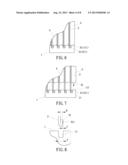
[0011] FIG. 1 is a perspective view of the heat radiator according to the present invention before pressing;
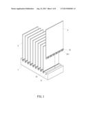
[0012] FIG. 2 is a perspective view showing the heat radiating fin of the present invention;
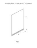
[0013] FIG. 3 is a partial perspective view showing the heat radiating fin of the present invention;
[0014] FIG. 4 is another partial perspective view showing the heat radiating fin of the present invention;
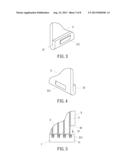
[0015] FIG. 5 is a schematic view of the heat radiating fin of the present invention during a pressing step;
[0016] FIG. 6 is a schematic view of the heat radiator of the present invention after pressing;
[0017] FIG. 7 is a schematic view showing the press head being retracted after pressing;
[0018] FIG. 8 is a schematic view showing the heat radiating fin before it is inserted into the groove of the base;
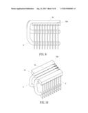
[0019] FIG. 9 is a front view of the heat radiator with the conductive pipes according to an embodiment of the present invention;
[0020] FIG. 10 is a perspective view of FIG. 9;
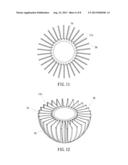
[0021] FIG. 11 is a top view showing the circular base according to another embodiment of the present invention;
[0022] FIG. 12 is a perspective view of FIG. 11;
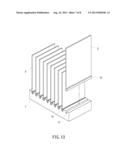
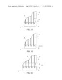
[0023] FIG. 13 is a perspective view of a heat radiator according to another embodiment of the present invention before pressing;
[0024] FIG. 14 is a schematic view of FIG. 13 during a pressing step;
[0025] FIG. 15 is a schematic view of FIG. 13 after pressing; and
[0026] FIG. 16 is a schematic view of FIG. 13 showing the press head being retracted after pressing.
DETAILED DESCRIPTION OF THE PREFERRED EMBODIMENTS
[0027] Embodiments of the present invention will now be described, by way of example only, with reference to the accompanying drawings.
[0028] As shown in FIG. 1, the heat radiator according to a preferred embodiment of the present invention comprises a base 1 and a plurality of heat radiating fins 2.
[0029] The base 1 has a surface formed with a plurality of grooves 11 for insertion of the plurality of heat radiating fins 2.
[0030] As shown in FIG. 2 to FIG. 4, the shape and the size of the plurality of heat radiating fins 2 are not limited. Each heat radiating fin 2 has a bent portion 21 at an insertion end thereof. The bent portion 21 has a plurality of spaced protrusions 211 which are formed by extrusion. The bent portion 21 is embedded in the related groove 11 of the base 1.
[0031] After the bent portion 21 of each heat radiating fin 2 is inserted into the related groove 11 of the base 1, a press head 3 is aligned with the embedded bent portion 21 for pressing, as shown in FIG. 5. The press head 3 has an inclined surface 31 to cover the bent portion 21 and a side wall of the related groove 11. After pressing as shown in FIG. 6, the bent portion 21 is deformed and enlarged in the related groove 11 to engage with the related groove 11 as shown in FIG. 7. The side wall of the related groove 11 is compressed by the inclined surface 31 of the press head 3 to be shifted and deformed. The deformed side wall 111 holds against the protrusions 211 of the bent portion 21, so that the heat radiating fins 2 and the base 1 are firmly connected. The heat radiating fins 2 won't shake to disengage from the base 1.
[0032] As shown in the drawings of the aforesaid embodiment, the protrusions 211 of each heat radiating fin 2 incline upward. After being pressed by the press head 3, the deformed side wall 111 extends outward to press the protrusions 211 of the bent portion 21. The other part of the bent portion 21 is compressed and deformed to fill up the related groove 11 of the base 1, such that the heat radiating fin 2 is stably connected to the groove 11 of the base.
[0033] As shown in FIG. 8, the width A of the groove 1 of the base 1 is slightly greater than the thickness B of the bent portion 21 of the heat radiating fin 2. The thickness B of the bent portion 21 plus the width C of the protrusion 211 equals the width A of the groove 11, namely, A=B+C.
[0034] FIG. 9 and FIG. 10 show another embodiment. The present invention can be connected with at least one conductive pipe 4 to constitute the heat radiator with conductive pipe. A bottom surface of the base 1a is formed with at least one engaging groove 12a for engagement of the conductive pipe 4. The conductive pipe 4 has a flat bottom surface 41 exposed and connected to the bottom surface of the base 1a. The conductive pipe 4 can be bent to penetrate the plurality of the heat radiating fins 2 so that the heat radiator with conductive pipe is assembled.
[0035] FIG. 11 and FIG. 12 show a further embodiment. The base lb of the present invention has a circle shape. The circular base lb has the plurality of grooves 11b formed around a circumferential wall thereof for insertion of the plurality of heat radiating fins 2b. The heat radiating fins 2b are radially connected to the circumferential wall of the circular base lb.
[0036] The shape, size and arrangement of the heat radiating fins 2 of the present invention can be changed as desired. The heat radiating fins 2 can be provided without the protrusions 211. FIG. 13 shows another embodiment. The bent portion 21 of each heat radiating fin 2 is directly embedded in the related groove 11 of the base 1, and then the press head 3 is aligned with the bent portion 21 to proceed with pressing as shown in FIG. 14 to FIG. 16. The press head 3 has the inclined surface 31 to cover the bent portion 21 and the side wall of the related groove 11. After pressing, the bent portion 21 is deformed and enlarged in the related groove 11 to engage with the related groove 11. The side wall of the related groove 11 is compressed by the inclined surface 31 of the press head 3 to be shifted and deformed. The deformed side wall 111 holds against the bent portion 21, so that the heat radiating fins 2 and the base 1 are firmly connected.
[0037] Accordingly, the heat radiating fins of the present invention are connected to the base of the heat radiator by pressing. This way of connection is clearly different from the prior art. In particular, the deformed side wall of the groove extends to hold against the bent portion 21 and the protrusions 211 to ensure stable connection of the heat radiating fins and the grooves of the base.
[0038] Although particular embodiments of the present invention have been described in detail for purposes of illustration, various modifications and enhancements may be made without departing from the spirit and scope of the present invention. Accordingly, the present invention is not to be limited except as by the appended claims.
User Contributions:
Comment about this patent or add new information about this topic:
| People who visited this patent also read: | |
| Patent application number | Title |
|---|---|
| 20190302483 | SPECTACLE LENS, METHOD FOR DESIGNING SPECTACLE LENS, AND METHOD FOR MANUFACTURING SPECTACLE LENS |
| 20190302482 | MATERIALS AND METHODS FOR MITIGATING THE HARMFUL EFFECTS OF BLUE LIGHT |
| 20190302481 | SPECTACLES AND ASSOCIATED METHODS FOR PRESBYOPIA TREATMENT AND MYOPIA PROGRESSION CONTROL |
| 20190302480 | EYEGLASS LENS, METHOD FOR DESIGNING EYEGLASS LENS, AND METHOD FOR MANUFACTURING EYEGLASS LENS |
| 20190302479 | OPTICAL LENS ASSEMBLIES AND RELATED METHODS |
Images included with this patent application:
 |  |
 |  |
 |  |
 |  |
 |
| Similar patent applications: | |
| Date | Title |
|---|---|
| 2010-06-24 | Liquid-cooled heat radiator |
| 2010-07-22 | Heat radiator of semiconductor package |
| 2010-09-30 | Heat radiating unit for adapter |
| 2012-03-08 | Baseboard heater radiator cover |
| 2013-08-22 | Hydraulic preheating apparatus for hydraulic oil coolers in a large hydraulic excavator |
| New patent applications from these inventors: | |
| Date | Title |
|---|---|
| 2016-05-26 | Aluminum pipe and heat pipe package and its packaging method |
| 2016-05-12 | Heat sink and mounting bracket arrangement |
| 2015-11-19 | Led lamp assembly |
| 2015-10-29 | Combination fin and heat pipe assembly |
| 2015-10-08 | Vapor chamber heat sink and method for making the same |
| Top Inventors for class "Heat exchange" | |
| Rank | Inventor's name |
|---|---|
| 1 | Levi A. Campbell |
| 2 | Chun-Chi Chen |
| 3 | Tai-Her Yang |
| 4 | Robert E. Simons |
| 5 | Richard C. Chu |