Patent application title: ALUMINUM PIPE AND HEAT PIPE PACKAGE AND ITS PACKAGING METHOD
Inventors:
Tsung-Hsien Huang (I-Lan Hsien, TW)
IPC8 Class: AF28D1502FI
USPC Class:
16510421
Class name: Intermediate fluent heat exchange material receiving and discharging heat liquid fluent heat exchange material utilizing change of state
Publication date: 2016-05-26
Patent application number: 20160146544
Abstract:
An aluminum pipe and heat pipe package formed by inserting a heat pipe
into a hollow aluminum pipe, and then processing the combination of the
heat pipe and hollow aluminum pipe through a series of extrusion molding
steps by means of opposing top and bottom extrusion dies and opposing
left and right necking dies to reduce the gap between the hollow aluminum
pipe and the heat pipe, and to have the hollow aluminum pipe and the heat
pipe to be peripherally tightly fitted together, and the two opposite
open ends of the hollow aluminum pipe to be completely blocked up.Claims:
1. An aluminum pipe and heat pipe packaging method, comprising the steps
of: a) inserting a heat pipe into a hollow aluminum pipe to obtain a
combination having a gap between the heat pipe and the hollow aluminum
pipe; b) processing the combination of said heat pipe and said hollow
aluminum pipe through a series of extrusion molding steps by means of
opposing top and bottom extrusion dies and opposing left and right
necking dies to reduce the gap between said hollow aluminum pipe and said
heat pipe, causing said hollow aluminum pipe and said heat pipe to be
peripherally tightly fitted together, and two opposite open ends of said
hollow aluminum pipe to be completely blocked up.
2. The aluminum pipe and heat pipe packaging method as claimed in claim 1, wherein said opposing top and bottom extrusion dies have die cavities thereof proportionally decreased in size in a predetermined order.
3. The aluminum pipe and heat pipe packaging method as claimed in claim 1, wherein said opposing left and right necking dies have necking die cavities thereof proportionally decreased in size in a predetermined order.
4. The aluminum pipe and heat pipe packaging method as claimed in claim 1, wherein said opposing top and bottom extrusion dies are respectively fixedly mounted at opposing top and bottom molds; said opposing left and right necking dies are respectively fixedly mounted at said opposing top and bottom molds at two opposite lateral sides relative to the respective said top and bottom extrusion dies.
5. An aluminum pipe and heat pipe package comprising a heat pipe, and a hollow aluminum pipe sleeved onto said heat pipe and peripherally tightly-fitted onto the periphery of said heat pipe, said hollow aluminum pipe having two opposite ends blocked up to secure said heat pipe tightly inside said hollow aluminum pipe.
Description:
BACKGROUND OF THE INVENTION
[0001] (a) Field of the Invention
[0002] The present invention relates to heat pipe technology, and more particularly to an aluminum pipe and heat pipe package made through a series of extrusion molding steps.
[0003] (b) Description of the Prior Art
[0004] A heat pipe is a closed evaporator-condenser system consisting of a sealed, hollow tube whose inside walls are lined with a capillary structure or wick. It combines both thermal conductivity and phase transition to efficiently manage the transfer of heat between two solid interfaces. Conventional heat pipes are made from copper. Due to the effects of the material properties, the copper body of a heat pipe is prone to burst in the casting mold in high-temperature environments, and brass body is prone to burst at a high temperature of die casting. An aluminum pipe can be wrapped about a heat pipe to enhance the overall structural strength, avoiding burst under a high temperature environment. Taiwan Patent M345223 discloses a sheathed flat heat pipe, which comprises a flat heat pipe, and a flat sleeve wrapped about the flat heat pipe in such a manner that the evaporator end of the flat heat pipe is exposed to the outside of the flat sleeve. Further, in "Metal-wrapped heat pipe processing method and heat pipe profile with a metal wrapping layer" of Taiwan Patent 1429489, a heat pipe is inserted into a hollow metal pipe (made of aluminum), and then the hollow metal pipe is stretched to extend its length and to reduce its diameter, and thus, the hollow metal pipe is tightly wrapped about the heat pipe to form a metal-wrapped heat pipe.
[0005] According to the cited 1429489 design, the hollow metal pipe is stretched to extend its length and to reduce its diameter, however, this method needs to employ a secondary machining process to block up the two opposite open ends of the hollow metal pipe in order to completely wrap the heat pipe inside the hollow metal pipe.
SUMMARY OF THE INVENTION
[0006] The present invention has been accomplished under the circumstances in view. It is therefore the main object of the present invention to provide an aluminum pipe and heat pipe package, which is formed by inserting a heat pipe into a hollow aluminum pipe, and then processing the combination of the heat pipe and hollow aluminum pipe through a series of extrusion molding steps by means of opposing top and bottom extrusion dies and opposing left and right necking dies to reduce the gap between the hollow aluminum pipe and the heat pipe, and to have the hollow aluminum pipe and the heat pipe to be peripherally tightly fitted together, and the two opposite open ends of the hollow aluminum pipe to be completely blocked up. Thus, the aluminum pipe and heat pipe package can easily be made without a secondary machining process, saving the manufacturing procedure and reducing the manufacturing cost.
BRIEF DESCRIPTION OF THE DRAWINGS
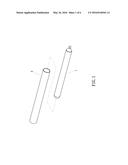
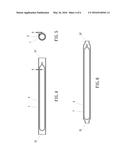
[0007] FIG. 1 is an exploded view of a hollow aluminum pipe and a heat pipe in accordance with the present invention.
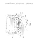
[0008] FIG. 2 is a schematic drawing illustrating the arrangement of opposing top and bottom extrusion dies and opposing left and right necking dies in opposing top and bottom molds in accordance with the present invention.
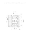
[0009] FIG. 3 is a sectional assembly view of FIG. 2.
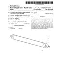
[0010] FIG. 4 is a longitudinal sectional view illustrating the heat pipe inserted into the hollow aluminum pipe in accordance with the present invention.
[0011] FIG. 5 is a cross sectional view of the assembly of FIG. 4.
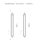
[0012] FIG. 6 is a schematic drawing illustrating the combination of the hollow aluminum pipe and heat pipe after a primary processing through a first stage extrusion molding step.
[0013] FIG. 7 is a schematic drawing illustrating the combination of the hollow aluminum pipe and heat pipe after a secondary processing through a second stage extrusion molding step.
[0014] FIG. 8 is a schematic drawing illustrating the combination of the hollow aluminum pipe and heat pipe processed after a third processing through a third stage extrusion molding step.
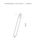
[0015] FIG. 9 is a perspective view of an aluminum pipe and heat pipe package.
DETAILED DESCRIPTION OF THE PREFERRED EMBODIMENTS
[0016] FIGS. 1-3 illustrate an aluminum pipe and heat pipe package and its packaging method in accordance with the present invention. At first, insert a heat pipe 1 into a hollow aluminum pipe 2, and then the combination of the heat pipe 1 and hollow aluminum pipe 2 is processed through a series of extrusion molding steps by means of opposing top and bottom extrusion dies 31a,32a (31b,32b; 31c,32c) and opposing left and right necking dies 41a,42a (41b,42b; 41c,42c) to reduce the gap G between the hollow aluminum pipe 2 and the heat pipe 1 (see FIG. 4 and FIG. 5), causing the hollow aluminum pipe 2 and the heat pipe 1 to be peripherally tightly fitted together, and the two opposite open ends 21,21' of the hollow aluminum pipe 2 to be completely blocked up, and thus, the hollow aluminum pipe 2 and the heat pipe 1 are packaged together.
[0017] In the aforesaid opposing top and bottom extrusion dies 31a,32a (31b,32b;31c,32c) and opposing left and right necking dies 41a,42a (41b,42b; 41c,42c):
[0018] The die cavities 311a,311b,311c of the top extrusion dies 31a,31b,31c, as shown in FIG. 3, are proportionally decreased in size in the order that 311a>311b>311c, and the die cavities 321a,321b,321c of the bottom extrusion dies 32a, 32b, 32c are similarly designed, i.e., 321a>321b>321c.
[0019] The necking die cavities 411a,411b,411c of the left necking dies 41a,41b,41c, as shown in FIG. 2, are proportionally decreased in size, i.e., 411a>411b>411c, and the necking die cavities 421a,421b,421c of the right necking dies 42a, 42b, 42c are similarly designed, i.e., 421a>421b>421c.
[0020] The opposing top and bottom extrusion dies 31a, 32a (31b,32b;31c,32c) are respectively fixedly mounted at opposing top and bottom molds 101,102, and the opposing left and right necking dies 41a,42a (41b,42b; 41c,42c) are respectively fixedly mounted at opposing top and bottom molds 101,102 at two opposite lateral sides relative to the respective top and bottom extrusion dies 31a, 32a (31b,32b;31c,32c). After insertion of the heat pipe 1 into the hollow aluminum pipe 2, and then the combination of the heat pipe 1 and hollow aluminum pipe 2 is processed through a series of extrusion molding steps by means of opposing top and bottom extrusion dies 31a,32a (31b,32b; 31c,32c) and opposing left and right necking dies 41a,42a (41b,42b; 41c,42c) to reduce the gap G between the hollow aluminum pipe 2 and the heat pipe 1, causing the hollow aluminum pipe 2 and the heat pipe 1 to be peripherally tightly fitted together, and the two opposite open ends 21,21' of the hollow aluminum pipe 2 to be completely blocked up (see FIGS. 6-8), and thus, the hollow aluminum pipe 2 and the heat pipe 1 are packaged together.
[0021] In the processing, the combination of the heat pipe 1 and hollow aluminum pipe 2 is primarily processed through a first stage extrusion molding step by means of the first top and bottom extrusion dies 31a,32a and the first left and right necking dies 41a,42a to reduce a part of the gap G between the hollow aluminum pipe 2 and the heat pipe 1 and to simultaneously contract the open ends 21,21' of the hollow aluminum pipe 2 at the first time (see FIG. 6). Thereafter, the primarily processed combination of the heat pipe 1 and hollow aluminum pipe 2 is then processed through a second stage extrusion molding step by means of the second top and bottom extrusion dies 31b,32b and the second left and right necking dies 41b,42b to further reduce the gap G between the hollow aluminum pipe 2 and the heat pipe 1 and to simultaneously contract the open ends 21,21' of the hollow aluminum pipe 2 at the second time (see FIG. 7). Thereafter, the secondarily processed combination of the heat pipe 1 and hollow aluminum pipe 2 is then processed through a third stage extrusion molding step by means of the third top and bottom extrusion dies 31c,32c and the third left and right necking dies 41c,42c to further reduce the gap G between the hollow aluminum pipe 2 and the heat pipe 1 and to simultaneously contract the open ends 21,21' of the hollow aluminum pipe 2 again (see FIG. 8), causing the hollow aluminum pipe 2 and the heat pipe 1 to be peripherally tightly fitted together, and the two opposite open ends 21,21' of the hollow aluminum pipe 2 to be completely blocked up, and thus, the hollow aluminum pipe 2 and the heat pipe 1 are combined into a package.
[0022] In conclusion, the invention enables the combination of the heat pipe 1 and hollow aluminum pipe 2 to be processed through a series of extrusion molding steps by means of multiple sets of opposing top and bottom extrusion dies and multiple sets of opposing left and right necking dies to reduce the gap G between the hollow aluminum pipe 2 and the heat pipe 1, causing the hollow aluminum pipe 2 and the heat pipe 1 to be peripherally tightly fitted together, and the two opposite open ends 21,21' of the hollow aluminum pipe 2 to be completely blocked up, and thus, the hollow aluminum pipe 2 and the heat pipe 1 are packaged together. In this embodiment, the combination of the heat pipe and hollow aluminum pipe is processed through three extrusion molding steps. However, the number of extrusion molding steps can be increased or reduced according to actual requirements without departing from the spirit and scope of the invention.
User Contributions:
Comment about this patent or add new information about this topic:
Images included with this patent application:
 |  |
 |  |
 |  |
 |
| Similar patent applications: | |
| Date | Title |
|---|---|
| 2015-11-12 | Pulsating multi-pipe heat pipe |
| 2016-01-14 | Aluminum heat exchanger |
| 2016-01-07 | Air passage opening/closing device |
| 2016-03-03 | Combined heat and power system |
| 2016-03-10 | Vehicle climate control method |
| New patent applications in this class: | |
| Date | Title |
|---|---|
| 2022-05-05 | Heat pipe and heat dissipation structure |
| 2016-12-29 | Cooling electronic devices in a data center |
| 2016-12-29 | Two-phase cooling devices with low-profile charging ports |
| 2016-12-29 | Personal thermal management system |
| 2016-09-01 | Heat exchange system and method |
| New patent applications from these inventors: | |
| Date | Title |
|---|---|
| 2016-05-12 | Heat sink and mounting bracket arrangement |
| 2015-11-19 | Led lamp assembly |
| 2015-10-29 | Combination fin and heat pipe assembly |
| 2015-10-08 | Vapor chamber heat sink and method for making the same |
| 2015-10-01 | Heat transfer plate and heat pipe mounting structure and method |
| Top Inventors for class "Heat exchange" | |
| Rank | Inventor's name |
|---|---|
| 1 | Levi A. Campbell |
| 2 | Chun-Chi Chen |
| 3 | Tai-Her Yang |
| 4 | Robert E. Simons |
| 5 | Richard C. Chu |