Patent application title: Method for Creating Switch Reluctance Motor Memory Sensor Model
Inventors:
Hao Chen (Xuzhou, CN)
Yan Liang (Xuzhou, CN)
IPC8 Class: AG06F1750FI
USPC Class:
703 13
Class name: Data processing: structural design, modeling, simulation, and emulation simulating electronic device or electrical system
Publication date: 2015-12-17
Patent application number: 20150363529
Abstract:
A method for creating a switch reluctance motor memory sensor model. A
switch reluctance motor memory sensor circuit model is formed by two
current transmitters AD844, an operational amplifier AD826, a memristor,
a capacitor, and three resistors. The method for creating a switch
reluctance motor memory sensor model enables physical phenomena in a
simulation system to be similar to an actual switch reluctance motor
system, and is beneficial for direct mathematical simulation of a switch
reluctance motor system. The method is simple, can improve static and
dynamic performance of a system, and achieves real-time simulation and
real-time control of the switch reluctance motor system.Claims:
1. A modelling method for a memory sensor model of a switch reluctance
motor, wherein: a) two current conveyors AD844, an operational amplifier
AD826 and a memory resistor are utilized, wherein the terminal voltage of
the input ports A-B of the memory sensor is U1, and the current
flowing into the memory sensor from the input port A thereof is i1;
b) the input port A of the memory sensor is connected with an in-phase
input port (3) of the current conveyor AD844-1 that is in turn connected
with a port (5) of the current conveyor AD844-2; an out-phase input port
(2) of the current conveyor AD844-1 is connected with one end of a
resistor Ri, the other end of which is connected with the ground;
the port (5) of the current conveyor AD844-1 is connected with one end of
a capacitor Ci, the other end of which is connected with the ground;
the out-phase input port (2) of the current conveyor AD844-2 is connected
with one end of a resistor Rx, the other end of which is connected
with the ground; the input port B of the memory sensor is connected with
the ground, the output port (6) of the current conveyor AD844-1 is
connected with one end of a memory resistor RM, the other end of
which is connected with the out-phase input port (2) of the operational
amplifier AD826; U2 is a voltage drop on the memory resistor,
i2 is a current in the memory resistor; the out-phase input port (2)
of the operational amplifier AD826 is also connected with one end of a
resistor Rd, the other end of which is connected with an output port
(1) of the operational amplifier AD826; the output port (1) of the
operational amplifier AD826 is also connected with an in-phase input port
(3) of the current conveyor AD844-2; and the in-phase input port (3) of
the operational amplifier AD826 is connected with the ground; a memory
sensor circuit model is obtained at the input ports A-B of the memory
sensor, and the equivalent inductance L thereof is expressed as: L = C
i R i R M R x R d . ##EQU00003##Description:
I. TECHNICAL FIELD
[0001] The present invention relates to a modelling method for a switch reluctance motor memory sensor model, which is especially suitable for switch reluctance motors with different phases.
II. BACKGROUND ART
[0002] A linear model of the switch reluctance motor ignores nonlinear factors such as magnetic saturation, such that the phase inductance of the switch reluctance motor is only associated with the positional angle of the rotor thereof, but not with the magnitude of phase current. Therefore, the linear model of the switch reluctance motor results in a big error in the optimization design, the quantitative analysis of the static and dynamic performance, the evaluation of control strategy and the like of the motor. As the switch reluctance motor itself has local magnetic saturation and a nonlinear magnetic circuit, and the power converter thereof is in a switch mode and has a nonlinear circuit topology, the phase inductance of the switch reluctance motor has a nonlinear property, which is not only associated with the positional angle of the rotor thereof, but also with the magnitude of phase current. Creating an accurate nonlinear model for the switch reluctance motor facilitates to increase the accuracy for the optimization design, the quantitative analysis of the static and dynamic performance, the evaluation of control strategy and the like of the motor. Phase inductance nonlinear modelling of the switch reluctance motor is the key for creating an accurate nonlinear model for the switch reluctance motor, however, it is difficult to utilize a traditional modelling method for a motor in the modelling of a switch reluctance motor. Phase inductance digitize nonlinear modelling for the switch reluctance motor requires a simulator and a controller to have great computing power in simulation and actual control, causing a conflict between operation cost and instantaneity of a system. Direct mathematical simulation enables physical phenomena in a simulation system to be similar to an actual system. The memory sensor is controlled by a magnetic linkage, is provided with a magnetic linkage-current hysteresis loop and is able to simulate the nonlinear relation between the phase inductance of the switch reluctance motor and the positional angle of the rotor and the magnitude of the phase current thereof. Creating a memory sensor model for the switch reluctance motor by using a hardware circuit is a direct mathematical simulation. This modelling method lays a foundation for circuit hardware modelling of the switch reluctance motor system model, and is beneficial for realizing direct mathematical simulation of a switch reluctance motor system and enables physical phenomena in the simulation system to be similar to an actual switch reluctance motor system.
III. CONTENTS OF THE INVENTION
[0003] The object of the present invention is to provide a linear modelling method for a memory resistor of a switch reluctance motor to overcome existing problems in prior art, which is simple and is able to improve the dynamic and static performance of a system and to enable the real-time simulation and real-time control of a switch reluctance motor system.
[0004] The modelling method for a memory sensor model of a switch reluctance motor in the present invention is as follows:
[0005] a) two current conveyors AD844, an operational amplifier AD826 and a memory resistor are utilized, wherein the terminal voltage of the input ports A-B of the memory sensor is U1, and the current flowing into the memory sensor from the input port A thereof is i1;
[0006] b) the input port A of the memory sensor is connected with an in-phase input port of the current conveyor AD844-1 that is in turn connected with a port of the current conveyor AD844-2; an out-phase input port of the current conveyor AD844-1 is connected with one end of a resistor Ri, the other end of which is connected with the ground; the port of the current conveyor AD844-1 is connected with one end of a capacitor Ci, the other end of which is connected with the ground; the out-phase input port of the current conveyor AD844-2 is connected with one end of a resistor Rx, the other end of which is connected with the ground; the input port B of the memory sensor is connected with the ground; the output port of the current conveyor AD844-1 is connected with one end of a memory resistor RM, the other end of which is connected with the out-phase input port of the operational amplifier AD826; U2 is a voltage drop on the memory resistor, i2 is a current in the memory resistor; the out-phase input port of the operational amplifier AD826 is also connected with one end of a resistor Rd, the other end of which is connected with an output port of the operational amplifier AD826; the output port of the operational amplifier AD826 is also connected with an in-phase input port of the current conveyor AD844-2; and the in-phase input port of the operational amplifier AD826 is connected with the ground; a memory sensor circuit model is obtained at the input ports A-B of the memory sensor, and the equivalent inductance L thereof is expressed as:
[0006] L = C i R i R M R x R d ##EQU00001## Benefits: There are following beneficial effects: the present invention creates a memory sensor model for the switch reluctance motor by using a hardware circuit, which is direct mathematical simulation, enables physical phenomena in a simulation system to be similar to an actual switch reluctance motor system, and has low hardware cost and strong instantaneity for simulation and actual control; it is based on a passive two-end element of a memory resistor RM, such that the phase inductance of the switch reluctance motor has a nonlinear property, which is not only associated with the positional angle of the rotor thereof, but also with the magnitude of phase current; it lays a foundation for circuit hardware modelling of the switch reluctance motor system model and is beneficial for realizing direct mathematical simulation of a switch reluctance motor system. In the simulation and actual control of phase inductance nonlinear modelling of the switch reluctance motor, it is not necessary for the simulator and the controller to have great computing power, solving the conflict between cost of simulation and actual control with the instantaneity of the switch reluctance motor system; furthermore, it is beneficial to increase the accuracy for the optimization design, the quantitative analysis of the static and dynamic performance and the evaluation of control strategy of the switch reluctance motor, such that it has great theoretical value and wide application prospect.
IV. DESCRIPTION OF DRAWINGS
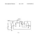
[0007] FIG. 1 is a view of a memory sensor model of a switch reluctance motor of the present invention.
V. EMBODIMENTS
[0008] One embodiment of the present invention is further described below in conjunction with the drawings:
[0009] As shown in FIG. 1, the modelling method for a memory sensor model of a switch reluctance motor in the present invention is as follows:
[0010] a) two current conveyors AD844, an operational amplifier AD826 and a memory resistor are utilized, wherein the terminal voltage of the input ports A-B of the memory sensor is U1, and the current flowing into the memory sensor from the input port A thereof is ii;
[0011] b) the input port A of the memory sensor is connected with an in-phase input port 3 of the current conveyor AD844-1 that is in turn connected with a port 5 of the current conveyor AD844-2; an out-phase input port 2 of the current conveyor AD844-1 is connected with one end of a resistor Ri, the other end of which is connected with the ground; the port 5 of the current conveyor AD844-1 is connected with one end of a capacitor Ci, the other end of which is connected with the ground; the out-phase input port 2 of the current conveyor AD844-2 is connected with one end of a resistor Rx, the other end of which is connected with the ground; the input port B of the memory sensor is connected with the ground, the output port 6 of the current conveyor AD844-1 is connected with one end of a memory resistor RM, the other end of which is connected with the out-phase input port 2 of the operational amplifier AD826; U2 is a voltage drop on the memory resistor, i2 is a current in the memory resistor; the out-phase input port 2 of the operational amplifier AD826 is also connected with one end of a resistor Rd, the other end of which is connected with an output port 1 of the operational amplifier AD826; the output port 1 of the operational amplifier AD826 is also connected with an in-phase input port 3 of the current conveyor AD844-2; and the in-phase input port 3 of the operational amplifier AD826 is connected with the ground; a memory sensor circuit model is obtained at the input ports A-B of the memory sensor, and the equivalent inductance L thereof is expressed as:
[0011] L = C i R i R M R x R d ##EQU00002## For this memory sensor model of the switch reluctance motor in the simulation and actual control of phase inductance nonlinear modelling of the switch reluctance motor, it is not necessary for the simulator and the controller to have great computing power, resolving the conflict between cost of simulation and actual control with the instantaneity of the switch reluctance motor system; and it is beneficial to increase the accuracy for the optimization design, the quantitative analysis of the static and dynamic performance and the evaluation of control strategy of the switch reluctance motor.
User Contributions:
Comment about this patent or add new information about this topic:
Images included with this patent application:
 |  |
| Similar patent applications: | |
| Date | Title |
|---|---|
| 2015-12-24 | Generating tubes within three-dimensional models |
| 2016-03-24 | Method and system for creating contact center models |
| 2016-03-31 | Method and system for analyzing the uncertainty of subsurface model |
| 2016-05-05 | Method of upscaling a discrete fracture network model |
| 2016-05-05 | Balancing provenance and accuracy tradeoffs in data modeling |
| New patent applications in this class: | |
| Date | Title |
|---|---|
| 2016-09-01 | Verified runtime validation of verified cyber-physical system models |
| 2016-07-07 | Simulating a large network load |
| 2016-06-30 | Method and apparatus for converged analysis of application, virtualization, and cloud infrastructure resources using graph theory and statistical classification |
| 2016-06-16 | Simulation device and simulation program |
| 2016-06-02 | Common plant model for modeling physical plant items of a production plant |
| New patent applications from these inventors: | |
| Date | Title |
|---|---|
| 2014-11-20 | Position sensorless control method for switched reluctance generator |
| 2014-11-20 | Position sensorless step-wise freewheeling control method for switched reluctance motor |
| Top Inventors for class "Data processing: structural design, modeling, simulation, and emulation" | |
| Rank | Inventor's name |
|---|---|
| 1 | Dorin Comaniciu |
| 2 | Charles A. Taylor |
| 3 | Bogdan Georgescu |
| 4 | Jiun-Der Yu |
| 5 | Rune Fisker |