Patent application title: TOUCH SCREEN AND APPARATUS OF DRIVING THE SAME
Inventors:
Yaw-Guang Chang (Tainan City, TW)
Yaw-Guang Chang (Tainan City, TW)
Wei-Song Wang (Tainan City, TW)
Chang-Hui Lin (Tainan City, TW)
Assignees:
HIMAX TECHNOLOGIES LIMITED
IPC8 Class: AG06F3044FI
USPC Class:
345174
Class name: Display peripheral interface input device touch panel including impedance detection
Publication date: 2014-12-25
Patent application number: 20140375591
Abstract:
In apparatus of driving a touch screen, a transmitter (TX) driving unit
generates TX driving signals coupled to a TX electrode substrate, and
receiver (RX) detection signals are then induced on an RX electrode
substrate that is coupled to and detected by an RX detection unit. A
plurality of the TX driving signals are simultaneously generated and fed
to the TX electrode substrate, and the TX driving signals during a given
period have different phases, respectively.Claims:
1. Apparatus of driving a touch screen, which comprises a transmitter
(TX) electrode substrate and a receiver (RX) electrode substrate, the
apparatus comprising: a TX driving unit configured to generate TX driving
signals coupled to the TX electrode substrate, RX detection signals being
then induced on the RX electrode substrate that is coupled to and
detected by an RX detection unit; wherein a plurality of the TX driving
signals are simultaneously generated and fed to the TX electrode
substrate, and the TX driving signals during a given period have
different phases, respectively.
2. The apparatus of claim 1, wherein the TX electrode substrate is patterned with a plurality of TX electrode lines coupled to receive the TX driving signals.
3. The apparatus of claim 2, wherein the RX electrode substrate is patterned with a plurality of RX electrode lines coupled to the RX detection unit.
4. The apparatus of claim 1, wherein the TX driving signals of all periods have a same overall DC value.
5. The apparatus of claim 1, wherein the TX driving signals of each period have a non-zero overall DC value.
6. The apparatus of claim 1, wherein the TX driving unit comprises: means for coupling to a high voltage; means for coupling to a low voltage; a first switch, via which the high voltage is controllably outputted as the TX driving signal; and a second switch, via which the low voltage is controllably outputted as the TX driving signal; wherein the first switch and the second switch are controlled by a switching control signal and an inverted switching control signal, respectively, such that the TX driving signal is obtained by alternately coupling to the high voltage and the low voltage via the first switch and the second switch, respectively.
7. A touch screen, comprising: a transmitter (TX) electrode substrate; a TX driving unit configured to generate TX driving signals coupled to the TX electrode substrate; a receiver (RX) electrode substrate, on which RX detection signals being then induced due to the TX driving signals; and an RX detection unit configured to detect the RX detection signals; wherein a plurality of the TX driving signals are simultaneously generated and fed to the TX electrode substrate, and the TX driving signals during a given period have different phases, respectively.
8. The touch screen of claim 7, wherein the TX electrode substrate is patterned with a plurality of TX electrode lines coupled to receive the TX driving signals.
9. The touch screen of claim 8, wherein the RX electrode substrate is patterned with a plurality of RX electrode lines coupled to the RX detection unit.
10. The touch screen of claim 7, wherein the TX driving signals of all periods have a same overall DC value.
11. The touch screen of claim 7, wherein the TX driving signals of each period have a non-zero overall DC value.
12. The touch screen of claim 7, wherein the TX driving unit comprises: means for coupling to a high voltage; means for coupling to a low voltage; a first switch, via which the high voltage is controllably outputted as the TX driving signal; and a second switch, via which the low voltage is controllably outputted as the TX driving signal; wherein the first switch and the second switch are controlled by a switching control signal and an inverted switching control signal, respectively, such that the TX driving signal is obtained by alternately coupling to the high voltage and the low voltage via the first switch and the second switch, respectively.
Description:
BACKGROUND OF THE INVENTION
[0001] 1. Field of the Invention
[0002] The present invention generally relates to a touch screen, and more particularly to apparatus of simultaneously driving multiple signals in a touch screen.
[0003] 2. Description of Related Art
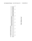
[0004] A touch screen is an input/output device that combines touch technology and display technology to enable users to directly interact with what is displayed. FIG. 1 shows waveforms of driving signals conventionally used to drive a touch screen. Specifically, during period t0 to t3, while a first electrode line associated with a driving signal TX1 is driven, other electrode lines (e.g., a second and a third electrode lines associated with driving signals TX2 and TX3) should be waited. In the same manner, the second electrode line is driven during period t3 to t6, and the third electrode line is driven during period t6 to t9. Therefore, a large amount of time from t0 to t9 is needed to complete driving three electrode lines.
[0005] It is worth noting that the conventional driving scheme demonstrated above cannot be adapted to an advanced touch screen with bigger panel size and/or larger resolution for the reason that a signal processor cannot complete driving and detection in time without detection loss.
[0006] Some schemes have been proposed to accelerate the driving, for example, by simultaneously driving multiple electrode lines. However, most schemes incur sharp increase in their overall value, thereby resulting in increasing the complexity of detection.
[0007] For the foregoing reasons, a need has arisen to propose a novel scheme to increase driving speed without adverse effect.
SUMMARY OF THE INVENTION
[0008] In view of the foregoing, it is an object of the embodiment of the present invention to provide apparatus of driving a touch screen to substantially increase the driving speed without incurring sharp increase in DC value.
[0009] According to one embodiment, a touch screen includes a transmitter (TX) electrode substrate, a TX driving unit, a receiver (RX) electrode substrate and an RX detection unit. The TX driving unit is configured to generate TX driving signals coupled to the TX electrode substrate. RX detection signals are then induced on the RX electrode substrate due to the TX driving signals. The RX detection unit is configured to detect the RX detection signals. A plurality of the TX driving signals are simultaneously generated and fed to the TX electrode substrate, and the TX driving signals during a given period have different phases, respectively.
BRIEF DESCRIPTION OF THE DRAWINGS
[0010] FIG. 1 shows waveforms of driving signals conventionally used to drive a touch screen;
[0011] FIG. 2 shows a schematic diagram illustrating apparatus of driving a touch screen according to one embodiment of the present invention;
[0012] FIG. 3A schematically shows an example illustrative of driving the touch screen according to one embodiment of the present invention;
[0013] FIG. 3B shows exemplary phases and DC values of FIG. 3A;
[0014] FIG. 3C shows another example of phases and DC values; and
[0015] FIG. 4 schematically shows a circuit of generating a TX driving signal.
DETAILED DESCRIPTION OF THE INVENTION
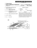
[0016] FIG. 2 shows a schematic diagram illustrating apparatus of driving a touch screen 100 according to one embodiment of the present invention. The touch screen 100 may, but not necessarily, be an in-cell touch screen that is an electronic visual display with sensing electrode layers disposed within a liquid crystal module (LCM). For better understanding the embodiment, only touch portion of the touch screen 100 is shown in FIG. 2. In the embodiment, the touch screen 100 includes a transmitter (TX) electrode substrate 11, which is patterned with a plurality of TX electrode lines 111 that are disposed substantially parallel to each other. Although line-shaped TX electrode lines 111 are exemplified in FIG. 2, the TX electrode lines 111 may have other shape such as rhombus. The touch screen 100 also includes a receiver (RX) electrode substrate 12 patterned with a plurality of RX electrode lines 121 that are disposed substantially parallel to each other. Although line-shaped RX electrode lines 1221 are exemplified in FIG. 2, the RX electrode lines 121 may have other shape such as rhombus. The TX electrode lines 111 may, but not necessarily, be substantially perpendicular to the RX electrode lines 121.
[0017] As shown in FIG. 2, the TX electrode lines 111 are coupled to respectively receive TX driving signals from a TX driving unit 13. An RX detection unit 14 is coupled to receive RX detection, signals from the RX electrode lines 121, respectively. The RX detection signals are induced by capacitances between the TX electrode lines 111 and the RX electrode lines 121, and the capacitances may be affected, for example, by a finger touched above the RX electrode substrate 12. Therefore, the induced RX detection signal with affected capacitance may then be used, in companion with the driven TX electrode line, to determine the touched position.
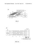
[0018] FIG. 3A schematically shows an example illustrative of driving the touch screen 100 according to one embodiment of the present invention. In the embodiment, a plurality (e.g., 3 as exemplified in FIG. 3A) of TX driving signals are simultaneously generated and fed to corresponding TX electrode lines, respectively, which need not be adjacent to each other.
[0019] According to one aspect of the embodiment, as exemplified in FIG. 3B with odd number of TX driving signals, the TX driving signals during a given period (e.g., t90 to t1) have different phases. For example, during the period between t0 and t1, the first TX driving signal TX1 has a positive phase (+), the second TX driving signal TX2 has a positive phase (+), and the third TX driving signal TX3 has a negative phase (-). As a result, an overall (or effective) direct-current (DC) value (e.g., 1) of the TX driving signals during a given period will not incur a sharp increase. Compared with conventional driving scheme as shown in FIG. 1, the driving scheme of the embodiment (FIG. 3A and FIG. 3B) can maintain the same DC value while increasing driving speed three times. FIG. 3C shows another example with even number of TX driving signals. Similar to the result shown in FIG. 3B, an overall (or effective) direct-current (DC) value (e.g., 2) of the TX driving signals during a given period will not incur a sharp increase.
[0020] According to another aspect of the embodiment, the TX driving signals of all periods have the same overall DC value. As exemplified in FIG. 3B, the TX driving signals of all periods have the same DC value of 1. Moreover, in the embodiment, the TX driving signals of each period have a non-zero (i.e., either positive or negative) overall DC value.
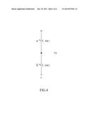
[0021] The TX driving signal of the embodiment may be generated by using a variety of circuit design technique. For example, as schematically shown in FIG. 4, the TX driving signal with a positive phase may be obtained by alternately coupling to a high voltage (H) and a low voltage (L) via switches SW1 and SW2, respectively, which are controlled by switching control signals φ and inverted φ, respectively. A TX driving signal with a negative phase may be obtained by interchanging the switching control signals φ and inverted φ; or be obtained by inverting the TX driving signal with the positive phase, for example, by an inverter. It is appreciated that the high voltage (H) and/or the low voltage (L) may be further derived, for example, by a pump circuit, from a voltage with less magnitude.
[0022] According to the embodiment described above, the driving speed may be substantially increased without incurring sharp increase in DC value.
[0023] Although specific embodiments have been illustrated and described, it will be appreciated by those skilled in the art that various modifications may be made without departing from the scope of the present invention, which is intended to be limited solely by the appended claims.
User Contributions:
Comment about this patent or add new information about this topic:
Images included with this patent application:
 |  |
 |  |
 |
| Similar patent applications: | |
| Date | Title |
|---|---|
| 2015-04-30 | Visualization, sharing and analysis of large data sets |
| 2015-04-30 | Touch mouse and touch control circuit board thereof |
| 2015-04-30 | Touch panel and method of manufacturing the same |
| 2015-04-30 | Touch panel and touch electrode structure thereof |
| 2015-04-30 | Display apparatus and driving method thereof |
| New patent applications in this class: | |
| Date | Title |
|---|---|
| 2022-05-05 | System and method for detecting and characterizing touch inputs at a human-computer interface |
| 2022-05-05 | Touchscreen calibration circuit |
| 2022-05-05 | Touch panel and touch panel operation method thereof |
| 2022-05-05 | Electronic device including a sensor layer |
| 2022-05-05 | Touch panel, touch screen and display device |
| Top Inventors for class "Computer graphics processing and selective visual display systems" | |
| Rank | Inventor's name |
|---|---|
| 1 | Katsuhide Uchino |
| 2 | Junichi Yamashita |
| 3 | Tetsuro Yamamoto |
| 4 | Shunpei Yamazaki |
| 5 | Hajime Kimura |