Patent application title: ROAD LAMP COOLING MANAGEMENT DEVICE
Inventors:
Wen-Sheng Hsiao (Guishan Township, TW)
Assignees:
EMpower Optronics Corp.
IPC8 Class: AF28F700FI
USPC Class:
165185
Class name: Heat exchange heat transmitter
Publication date: 2013-01-03
Patent application number: 20130000879
Abstract:
The present invention relates to a road lamp cooling management device
including a plurality of cooling pipes installed into fins of an LED
light source coupled to the large road lamp, and an open end of each of
cooling pipes is inserted and fixed directly into a fixing hole base of
an upper lamp casing, such that high heat generated by the LED light
source can be cooled by the fins as a first-stage cooling and circulated
and cooled by the plurality of cooling pipes as a second-stage cooling.Claims:
1. A road lamp cooling management device, particularly a large road lamp
cooling management device using a light emitting diode (LED) as a light
source, comprising a plurality of cooling pipes installed into a
plurality of fins coupled to the LED light source, and an open end of
each of the cooling pipes being inserted and fixed directly into a fixing
hole base of an upper lamp casing, such that high heat generated by the
LED light source during the illumination of the large road lamp is cooled
by the fins as a first-stage cooling, and then circulated and cooled by
the plurality of cooling pipes as a second-stage cooling, so as to
achieve the effects of preventing the LED light source from being burned
by the high heat, allowing the large road lamp to operate normally,
reducing damages and losses, and enhancing the service life of the road
lamp.Description:
BACKGROUND OF THE INVENTION
[0001] 1. Field of the Invention
[0002] The present invention relates to a road lamp cooling management device, in particular to a large road lamp cooling management device using a light emitting diode (LED) as a light source, and the high heat generated by the LED is cooled by two stages, such that the LED light source will not be burned by overheat, and the large road lamp can achieve the effects of providing normal illuminations, reducing damages and improving the service life.
[0003] 2. Description of the Prior Art
[0004] In general, a conventional large road lamp illumination device, particularly a large road lamp illumination device using a light emitting diode (LED) as a light source usually generate high heat, and the LED may be burned and damaged easily by overheat, if the high temperature cannot be dissipated timely. Although some related manufacturers adopt fins as a part of a lamp base and intend to dissipate the high heat through the exposed lamp base, yet the lamp base exposed to the outside for a long time will accumulate dust, thus affecting the heat dissipating effect of the lamp base severely, burning the LED light source, losing the illumination effect of the road lamp, and jeopardizing the traffic safety. This is a main subject for the present invention to overcome the aforementioned drawbacks of the prior art.
OBJECTS OF THE INVENTION
[0005] Therefore, it is a primary objective of the present invention to overcome the drawbacks of the conventional large road lamp illumination device, particularly the large road lamp illumination device using LED as a light source by providing a road lamp cooling management device with a novel design concept of a cooling management system, and a circulation system with cooling pipes is used to achieve a cooling effect and enhance the service life and performance of the LED light source, such that the large road lamp can be operated normally to provide illumination for a long time.
[0006] Another objective of the present invention is to provide a road lamp cooling management device, wherein cooling pipes are inserted and fixed onto an upper lamp casing. This design not only facilitates assembling the whole structure, but also conducting the heat source to the upper lamp casing for cooling circulations to lower the temperature of the LED light source, and enhance the service life and performance of the road lamp. In additon, the cooling pipes are arranged alternately with one another, or arranged perpendicularly in groups, but the present invention is not limited to such arrangements only.
SUMMARY OF THE INVENTION
[0007] A road lamp cooling management device of the present invention, particularly a large road lamp cooling management device using LED as a light source includes a plurality of fins coupled to the LED light source, and a plurality of cooling pipes, and an open end of each cooling pipe is inserted and fixed directly into a fixing hole base of an upper lamp casing, such that high heat generated by the LED light source during the use of the large road lamp can be cooled by the fins as a first-stage cooling, and also circulated and cooled by the plurality of cooling pipes as a second-stage cooling, so as to achieve the effects of preventing the LED light source from being burned by the high heat, allowing the large road lamp to operate normally, reducing damages and losses, and enhancing the service life.
BRIEF DESCRIPTION OF THE DRAWINGS
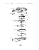
[0008] FIG. 1 is an exploded view of the whole structure of the present invention;
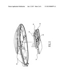
[0009] FIG. 2 is a schematic view of the main structure of the present invention;
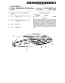
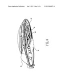
[0010] FIG. 3 is a perspective view of the structure of the present invention;
[0011] FIG. 4 is a cross-sectional view of a cooling pipe of the present invention;
[0012] FIG. 5 is a schematic view of installing a cooling pipe at a different position in accordance with the present invention; and
[0013] FIG. 6 is a schematic view of a cooling circulation of the present invention.
DETAILED DESCRIPTION OF THE PREFERRED EMBODIMENTS
[0014] The technical characteristics, effects and advantages of the present invention will become apparent with the detailed description of the following preferred embodiments and the illustration of related drawings as follows.
[0015] With reference to FIG. 1, the road lamp cooling management device of the present invention comprises a lower lamp casing 10 and an upper lamp casing 20, wherein the lower lamp casing 10 includes a light reflecting plate 11, a lamp shade 12, and a gasket 13, and these components are parts of the basic structure of the large road lamp and not the main technical characteristics of the present invention, and thus will not be described here. The upper lamp casing 20 includes two fins 30, 40, plurality of cooling pipes 50 installed between the two fins 30, 40, and the gasket 80 is a sealing gasket for coupling the lower lamp casing 10 and the upper lamp casing 20. In FIGS. 2 and 3, an LED light source 60 and a power supply 70 are mounted onto the fins 40 to constitute an illumination device.
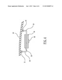
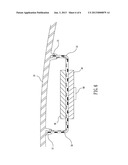
[0016] In FIG. 4, after the foregoing components are installed, the cooling pipe 50 is inserted directly into a fixing hole base 21 on the upper lamp casing 20 for cooling and circulating heat.
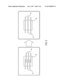
[0017] Based on the heat circulation design concept of the cooling pipes 50 in accordance with the present invention, the cooling pipes 50 can be arranged alternately with one another as shown on the left side of FIG. 5 or arranged perpendicularly in groups to achieve the desired cooling effect.
[0018] In FIG. 6, an open end of each cooling pipe 50 of the present invention is inserted and fixed directly into the fixing hole base 21 of the upper lamp casing 20, such that high heat generated by the LED light source 60 during the use of the road lamp can be cooled by the two fins 30, 40 as a first-stage cooling, and then circulated and cooled by the plurality of cooling pipes 50 as a second-stage cooling, so as to achieve the effect of preventing the LED light source 60 from being burned by the high heat, providing a normal operation of the large road lamp, reducing damages or losses, and enhancing the service life of the lamp.
[0019] In summation of the description above, the road lamp cooling management device of the present invention, particularly the large road lamp using LED as a light source adopts the design concept of a cooling pipe and complies with the patent application requirements, and is thus duly filed for patent application. While the invention has been described by means of specific embodiments, numerous modifications and variations could be made thereto by those skilled in the art without departing from the scope and spirit of the invention set forth in the claims.
User Contributions:
Comment about this patent or add new information about this topic:
Images included with this patent application:
 |  |
 |  |
 |  |
 |
| Similar patent applications: | |
| Date | Title |
|---|---|
| 2014-06-05 | Cooling device, and electronic apparatus with the cooling device |
| 2014-06-05 | Air-based cooling for data center rack |
| 2010-09-02 | Method and apparatus for rapidly cooling a gem |
| 2011-10-06 | Cooling arrangement |
| 2013-07-04 | System and method for hvac condensate management |
| Top Inventors for class "Heat exchange" | |
| Rank | Inventor's name |
|---|---|
| 1 | Levi A. Campbell |
| 2 | Chun-Chi Chen |
| 3 | Tai-Her Yang |
| 4 | Robert E. Simons |
| 5 | Richard C. Chu |