Patent application title: COOLER DEVICE
Inventors:
Tsung-Hsien Huang (I-Lan Hsien, TW)
IPC8 Class: AF28D1504FI
USPC Class:
16510426
Class name: Liquid fluent heat exchange material utilizing change of state utilizing capillary attraction
Publication date: 2011-12-01
Patent application number: 20110290449
Abstract:
A cooler device includes a metal base panel, radiation fins fastened to
the metal base panel at the top, and heat pipes fastened to the metal
base panel and respective top notches of the radiation fins. Each top
notch of each radiation fin has a narrow notch portion disposed at the
top side for a stamping die to pass and an expanded bottom notch portion
disposed at the bottom side for the cold end of one of the heat pipes to
insert through for enabling the inserted cold ends of the heat pipes to
be deformed and forced into engagement with the radiation fins by a
stamping machine by means of stamping dies.Claims:
1. A cooler device, comprising a base panel, a plurality of radiation
fins mounted on said base panel, and at least one heat pipe fastened to
said base panel and said radiation fins, wherein: each said radiation fin
comprises at least one top notch on a top side thereof, each said top
notch having a narrow notch portion disposed at a top side for a stamping
die to pass and an expanded bottom notch portion disposed at a bottom
side of said narrow notch portion for one end of one said heat pipe to
insert through for enabling the inserted end of said heat pipe to be
deformed and forced into engagement with each said radiation fin by a
stamping die; each said heat pipe has two distal ends thereof
respectively inserted through and affixed to said radiation fins and said
base panel; and said base panel is a flat metal block member having a top
wall configured for the mounting of said radiation fins.
2. The cooler device as claimed in claim 1, wherein the expanded bottom notch portion of each said top notch of each said radiation fin forms a hole having a polygonal shape.
3. The cooler device as claimed in claim 1, wherein the number of the at least one top notch of each said radiation fin is 4; and the number of said at least one heat pipe is 4, and the four heat pipes are arranged in said radiation fins and said base panel in parallel in one same direction.
4. The cooler device as claimed in claim 1, wherein the number of the at least one top notch of each said radiation fin is 4; and the number of said at least one heat pipe is 4, and the four heat pipes are arranged in said radiation fins and said base panel in parallel in two opposite directions.
5. The cooler device as claimed in claim 1, wherein each said radiation fin further comprises a bearing flange perpendicularly extending from one side thereof around the expanded bottom notch portion of each said top notch for supporting one end of each said heat pipe in the expanded bottom notch portion of each said top notch.
6. The cooler device as claimed in claim 1, wherein each said radiation fin further comprises a plurality of mounting lugs symmetrically disposed at two opposite lateral sides for fastening, and each mounting lug is fastened to a corresponding mounting lug of a neighboring radiation fin.
7. The cooler device as claimed in claim 1, wherein each said heat pipe has a hot end mounted in said base panel for absorbing waste heat, and a cold end mounted in said radiation fins for heat dissipation.
8. The cooler device as claimed in claim 1, wherein each said heat pipe has one end thereof press-fitted into a bottom wall of said base panel and kept in flush with the bottom wall of said base panel.
9. The cooler device as claimed in claim 1, wherein said base panel comprises a dovetail protrusion raised from the top wall thereof and a plurality of barbs located on two opposite lateral sides of said dovetail protrusion; each said radiation fin further comprises a dovetail groove located on a bottom side thereof and forced into engagement with said dovetail protrusion of said base panel.
10. The cooler device as claimed in claim 1, wherein said stamping dies are shaped like a flat bar, having a flat cutting edge.
Description:
BACKGROUND OF THE INVENTION
[0001] (a) Field of the Invention
[0002] The present invention relates to a cooler device for cooling a semiconductor electronic device and more particularly to such a cooler device in which the cold ends of heat pipes are respectively inserted into the bottom irregular holes (for example, polygonal holes) of the top notches of radiation fins and forced into engagement with the radiation fins tightly by a stamping machine by means of stamping dies.
[0003] (b) Description of the Prior Art
[0004] A conventional cooler device with heat pipe generally comprises a set of radiation fins, a base panel, and one or more heat pipes. The heat pipes are bonded to the radiation fins and the base panel with a solder paste. If the base panel and the heat pipes are made of different materials, a nickel chemical-plating procedure is necessary before bonding. This fabrication procedure is complicated and not environmentally friendly.
[0005] Mounting holes and slots may be formed on radiation fins and respectively connected together for the mounting of heat pipes. Convex-concave stamping dies are inserted into the slots and operated to stamp heat pipes, forcing heat pipes into engagement with radiation fins. According to this method, heat pipes are stamped to produce recessed portions on the outside wall and protruding portions on the inside wall. The formation of the protruding portions reduces the inner diameter of the heat pipes, thereby increasing fluid resistance.
SUMMARY OF THE INVENTION
[0006] The present invention has been accomplished under the circumstances in view. According to the invention, a cooler device comprises a base panel, a plurality of radiation fins mounted on the top side of the base panel, and a plurality of heat pipes inserted through the base panel and the radiation fins. Each radiation fin has a plurality of top notches for mounting the heat pipes. Each top notch of each radiation fin has a narrow notch portion disposed at the top side for the passing of a stamping die and an expanded bottom notch portion disposed at the bottom side for accommodating the cold end of one of the heat pipes. The expanded bottom notch portion of each top notch is essentially an irregular hole, for example. After insertion of the cold ends of the heat pipes into the expanded bottom notch portions of the top notches of the radiation fins, stamping dies are forced into the narrow notch portions of the top notches of the radiation fins and stamped against the cold ends of the heat pipes, forcing the cold ends of the heat pipes into engagement with the radiation fins.
[0007] Further, the expanded bottom notch portion of each top notch of each radiation fin can be a polygonal hole, for example, a hexagonal hole or octagonal hole, etc. When the cold end of one heat pipe is stamped by one stamping die, the heat pipe and the periphery of the expanded bottom notch portion of the associated top notch of the associated radiation fin are deformed and tightly engaged together.
[0008] Further, the heat pipes can be fastened to the top notches of the radiation fins in parallel in one same direction. Alternatively, the heat pipes can be fastened to the top notches of the radiation fins in parallel in two opposite directions.
[0009] Further, each radiation fin comprises a bearing flange perpendicularly extended from one side thereof around the expanded bottom notch portion of each top notch for supporting the cold ends of the heat pipes in the expanded bottom notch portions of the respective top notches.
[0010] Further, each radiation fin comprises a plurality of mounting lugs symmetrically disposed at two opposite lateral sides for fastening. By means of fastening the mounting lugs of one radiation fin to that of another, the radiation fins are fastened together in a parallel manner.
[0011] Further, the base panel comprises a dovetail protrusion raised from the top wall thereof, and a plurality of barbs located on two opposite lateral sides of the dovetail protrusion. Further, each radiation fin comprises a dovetail groove located on the bottom side thereof and forced into engagement with the dovetail protrusion of the base panel tightly.
BRIEF DESCRIPTION OF THE DRAWINGS
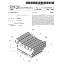
[0012] FIG. 1 is an elevational assembly view of a cooler device in accordance with the present invention.
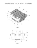
[0013] FIG. 2 is a front view of the cooler device shown in FIG. 1.
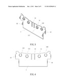
[0014] FIG. 3 is an oblique elevation of one radiation fin for the cooler device in accordance with the present invention.
[0015] FIG. 4 is a front view of the radiation fin shown in FIG. 3.
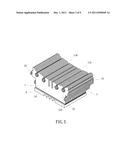
[0016] FIG. 5 is an oblique elevation of the cooler device in accordance with the present invention before installation of the heat pipes.
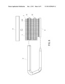
[0017] FIG. 6 is a schematic drawing of the present invention, showing how a heat pipe is mounted.
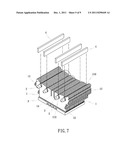
[0018] FIG. 7 is a schematic drawing of the present invention, showing stamping dies used before they are inserted into the radiation fins.
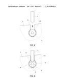
[0019] FIG. 8 is an enlarged view of a part of FIG. 7.
[0020] FIG. 9 corresponds to FIG. 8, showing the stamping die stamped against the cold end of the heat pipe.
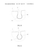
[0021] FIG. 10 shows an alternate form of the top notch of the radiation fin in accordance with the present invention.
[0022] FIG. 11 shows another alternate form of the top notch of the radiation fin in accordance with the present invention.
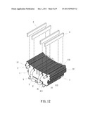
[0023] FIG. 12 is a schematic drawing of the present invention, showing the heat pipes installed in the radiation fins and the base panel in opposite directions.
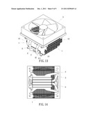
[0024] FIG. 13 illustrates an electrical fan mounted on the top side of the radiation fins of the cooler device in accordance with the present invention.
[0025] FIG. 14 is a bottom view of FIG. 13.
DETAILED DESCRIPTION OF THE PREFERRED EMBODIMENTS
[0026] As shown in FIGS. 1-5, a cooler device in accordance with the present invention comprises a set of radiation fins 1, a plurality of heat pipes 2, and a base panel 3.
[0027] As shown in FIGS. 3 and 4, each radiation fin 1 comprises a plurality of top notches 11 on the top side. Each top notch 11 has a narrow notch portion 110 and an expanded bottom notch portion 111. The expanded bottom notch portion 111 is an irregular hole that can be made in any of a variety of polygonal or other geometric shapes. According to this embodiment, the expanded bottom notch portion 111 is an octagonal hole. When the radiation fins 1 are arranged together in a parallel manner, the top notches 11 are respectively aligned in lines. Thus, stamping dies 4 can be inserted through the narrow notch portions 110 of the top notches 11 of the radiation fins 1 (see FIGS. 5 and 7).
[0028] The heat pipes 2 are sealed U-tubes made of a highly thermo-conductive material and filled with a working fluid or coolant and having a wick structure on the inside walls. Further, each heat pipe 2 has its one end, namely the hot end, inserted through the radiation fins 1, and its other end, namely the cold end, inserted through the base panel 3.
[0029] The base panel 3 is a metal panel extruded from aluminum, copper or other thermally conductive material, having a bottom wall for attaching to the heat source (for example, CPU) and a top wall for the mounting of the radiation fins 1.
[0030] Referring to FIGS. 6 and 7, the cold ends of the heat pipes 2 are respectively inserted through the expanded bottom notch portions 111 of the top notches 11 of the radiation fins 1, and then stamping dies 4 of a stamping machine (not shown) are respectively inserted through the narrow notch portions 110 of the top notches 11 of the radiation fins 1, and then the stamping machine is operated to stamp the stamping dies 4 against the cold ends of the heat pipes 2 and the radiation fins 1 (see FIG. 8), thereby tightening the engagement between the radiation fins 1 and the heat pipes 2.
[0031] According to this embodiment, each radiation fin 1 comprises four top notches 11 on the top side for the mounting of four heat pipes 2 in one same direction tightly (see FIG. 1). However, any number of top notches can be used if necessary.
[0032] Referring to FIGS. 10 and 11, the expanded bottom notch portion 111 of each top notch 11 of each radiation fin 1 can have any geometric shape (as shown in FIG. 10), or a hexagonal shape (as shown in FIG. 11). These are simply examples of the present invention, and not intended as a limitation.
[0033] Referring to FIG. 12, as an alternate form of the present invention, the four heat pipes 2 are tightly fitted into the expanded bottom notch portions 111 of the four top notches 11 on the top side the radiation fins 1 in a parallel manner in two opposite directions. Therefore, the heat pipes 2 can be tightly fitted into the radiation fins 21 and the base panel 3 in one same direction, or in opposite directions.
[0034] Referring to FIG. 3 again, each radiation fin 1 further comprises a bearing flange 112 perpendicularly extending from the front side (or back side) thereof around the expanded bottom notch portion 111 of each top notch 11 thereof for supporting one heat pipe 2 in the expanded bottom notch portion 111 of each top notch 11, assuring tight engagement between the heat pipes 2 and the radiation fins 1.
[0035] Referring to FIG. 3 again, each radiation fin 1 further comprises a plurality of mounting lugs 12 symmetrically disposed at two opposite lateral sides thereof. By means of fastening the mounting lugs 12 of one radiation fin 1 to the mounting lugs 12 of another radiation fin 1, the radiation fins 1 are connected together in a parallel manner.
[0036] Referring to FIGS. 12˜14, after the radiation fins 1, the heat pipes 2 and the base panel 3 are assembled, the hot ends of the heat pipes 2 are tightly kept in the base panel 3, and the cold ends of the heat pipes 2 are tightly kept in the radiation fins 1. Thereafter, an electrical fan 5 can be fixedly mounted on the top side of the radiation fins 1. When the electrical fan 5 is started, currents of air are induced through gaps in the radiation fins 1 to rapidly carry waste heat away, cooling the heat source (for example, CPU).
[0037] As shown in the accompanying drawings, the hot ends of the heat pipes 2 are tightly forced into the bottom side of the base panel 3 with the flat bottom walls thereof and exposed to the outside of the base panel 3 and kept in flush with the bottom wall of the base panel 3. However, this arrangement is merely an illustrative example, not a limitation. The hot ends of the heat pipes 2 may be embedded in the base panel 1 and not exposed to the outside of the base panel 1.
[0038] Referring to FIGS. 12˜14 again, the mounting arrangement between the radiation fins 3 and the base panel 1 can be done in such a manner that the base panel 3 comprises a dovetail protrusion 31 raised from the top wall thereof and extending between the front and rear sides thereof, and a plurality of barbs 311 located on two opposite lateral sides of the dovetail protrusion 31; each radiation fin 1 comprises a dovetail groove 13 on the bottom side thereof and forced into tight engagement with the dovetail protrusion 31 of the base panel 3.
[0039] The aforesaid stamping dies 4 are used with a matching machine tool. During processing, the machine tool or the parts of the machine tool are abutted against two opposite lateral sides of the set of radiation fins 1, and then the stamping dies 4 are moved vertically downwardly through the narrow notch portions 110 of the top notches 11 of the radiation fins 1 stamped against the cold ends of the heat pipes 2 and the radiation fins 1 to deform the periphery 21 of the heat pipes 2, thereby tightening the engagement between the radiation fins 1 and the heat pipes 2. Further, the stamping dies 4 are shaped like a flat bar, having a flat cutting edge.
[0040] Further, as shown in the accompanying drawings, each radiation fin 1 has at least one mounting slot 14 for the fixation of a CPU clamp.
[0041] Although particular embodiments of the invention have been described in detail for purposes of illustration, various modifications and enhancements may be made without departing from the spirit and scope of the invention. Accordingly, the invention is not to be limited except as by the appended claims.
User Contributions:
Comment about this patent or add new information about this topic:
Images included with this patent application:
 |  |
 |  |
 |  |
 |  |
 |  |
| Similar patent applications: | |
| Date | Title |
|---|---|
| 2008-08-21 | Case for a liquid submersion cooled electronic device |
| 2008-10-09 | Console air conditioner for vehicle |
| 2008-10-30 | Cooling components in electronic devices |
| 2008-11-13 | Circulation-type liquid cooling apparatus and electronic device containing same |
| 2009-01-01 | Cooling structure for heat generating device |
| New patent applications in this class: | |
| Date | Title |
|---|---|
| 2019-05-16 | Method for preparing porous wick and product prepared by the same |
| 2019-05-16 | Semiconductor device assembly with vapor chamber |
| 2019-05-16 | Straight-through structure of heat dissipation unit |
| 2018-01-25 | Diphasic cooling loop with satellite evaporators |
| 2017-08-17 | Heat pipe |
| New patent applications from these inventors: | |
| Date | Title |
|---|---|
| 2016-05-26 | Aluminum pipe and heat pipe package and its packaging method |
| 2016-05-12 | Heat sink and mounting bracket arrangement |
| 2015-11-19 | Led lamp assembly |
| 2015-10-29 | Combination fin and heat pipe assembly |
| 2015-10-08 | Vapor chamber heat sink and method for making the same |
| Top Inventors for class "Heat exchange" | |
| Rank | Inventor's name |
|---|---|
| 1 | Levi A. Campbell |
| 2 | Chun-Chi Chen |
| 3 | Tai-Her Yang |
| 4 | Robert E. Simons |
| 5 | Richard C. Chu |