Patent application title: Heat sink memory chip
Inventors:
Wei-Hau Chen (Taipei County, TW)
Steven Yen (Taipei County, TW)
IPC8 Class: AF28F700FI
USPC Class:
165 803
Class name: With retainer for removable article electrical component air cooled, including fins
Publication date: 2009-11-12
Patent application number: 20090277607
Inventors list |
Agents list |
Assignees list |
List by place |
Classification tree browser |
Top 100 Inventors |
Top 100 Agents |
Top 100 Assignees |
Usenet FAQ Index |
Documents |
Other FAQs |
Patent application title: Heat sink memory chip
Inventors:
Wei-Hau Chen
Steven Yen
Agents:
Wei-Hau Chen
Assignees:
Origin: TAIPEI, TW
IPC8 Class: AF28F700FI
USPC Class:
165 803
Patent application number: 20090277607
Abstract:
A heat sink for chips includes two heat dispensing units and each heat
dispensing unit includes multiple fins between which passages are
defined. Each heat dispensing unit includes a flat surface defined in an
inside thereof and a heat conducting member is connected to the flat
surface. The chip is in contact between the two heat conducting members
so that the heat generated from the chip is contacted to the heat
conducting members and the fins and escapes to the air.Claims:
1. A heat sink for chips, comprising:two heat dispensing units and each
heat dispensing unit including multiple fins, passages defined between
the multiple fins, a flat surface defined in an inside of each heat
dispensing unit and a heat conducting member connected to the flat
surface of each heat dispensing unit, the chip being in contact between
the two heat conducting members.
2. The heat sink as claimed in claim 1, wherein a clamp secures the fins and the fins are parallel to each other.
Description:
BACKGROUND OF THE INVENTION
[0001](1) Field of the Invention
[0002]The present invention relates to a heat sink for providing a larger heat dispensing area to the chips.
[0003](2) Description of the Prior Art
[0004]The chips used in electronic devices such as computers generate a significant heat during operation and the heat may damage the chips so that how to remove the heat from the chips becomes a serious problems. A conventional way to remove heat from the chip is to provide two heat dispensing plates between which the chip is clamped, the heat generated from the chip is conducted to the heat dispensing plates and escapes to the air.
[0005]However, the latest chips generate much higher heat than those made by old technology so that the conventional heat dispensing plates cannot remove the heat efficiently. This is because the area that heat is transferred from the chip is insufficient and the conventional heat dispensing plates can only remove a certain amount of heat because of limited heat dispensing area.
[0006]The present invention intends to provide a heat sink for chips and includes two heat dispensing units between which the chip is clamped. Each heat dispensing unit includes multiple fins between which passages are defined, so that heat can be efficiently removed from the chip by the heat dispensing units.
SUMMARY OF THE INVENTION
[0007]The present invention relates to a heat sink for chips and the heat sink comprises two heat dispensing units and each heat dispensing unit includes multiple fins between which passages are defined. A flat surface is defined in an inside of each heat dispensing unit and a heat conducting member is connected to the flat surface of each heat dispensing unit. The chip is in contact between the two heat conducting members.
[0008]The primary object of the present invention is to provide a heat sink which has a heat conducting member connected between the chip and multiple fins so as to efficiently remove heat from the chip.
[0009]The present invention will become more obvious from the following description when taken in connection with the accompanying drawings which show, for purposes of illustration only, a preferred embodiment in accordance with the present invention.
BRIEF DESCRIPTION OF THE DRAWINGS
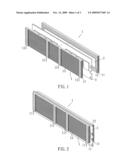
[0010]FIG. 1 is an exploded view to show the heat sink of the present invention and a chip;
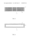
[0011]FIG. 2 is a perspective view to show the chip is clamped between the heat dispensing units of the heat sink of the present invention;
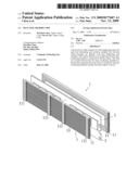
[0012]FIG. 3 shows an outside view of the heat unit of the heat sink of the present invention;
[0013]FIG. 4 shows an inside view of the heat unit of the heat sink of the present invention;
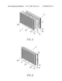
[0014]FIG. 5 is an exploded view to show another embodiment of the heat sink of the present invention and a chip, and FIG. 6 is a perspective view to show another chip is clamped between the heat dispensing units of the heat sink shown in FIG. 5.
DETAILED DESCRIPTION OF THE PREFERRED EMBODIMENTS
[0015]Referring to FIGS. 1 to 4, the heat sink of the present invention comprises two heat dispensing units 1 and each heat dispensing unit 1 includes multiple fins 11 which are secured by a clamp 111 so that the fins 11 are positioned to be parallel to each other. Passages 13 are defined between the multiple fins 11. A flat surface 12 is defined in an inside of each heat dispensing unit 1 and a heat conducting member 2 is connected to the flat surface 12 of each heat dispensing unit 1. The chip 3 such as a memory chip is in contact between the two heat conducting members 2.
[0016]The chip 3 generates heat which is conducted to the heat conducting members 2 which are directly connected with the fins 11 so that heat is then conducted to the fins 11 which provides sufficient area to allow the heat to escape to the air. When cooperated with a fan unit (not shown), the fan unit generates air flows flowing through the passages 13 to quickly bring heat out from the fins 11.
[0017]The present invention is simple and easily to use, the chip 3 is simply attached to the heat conducting members 2. Not like the conventional heat sink, the chip and the heat sink has to be connected to each other by clips.
[0018]Because each heat dispensing unit 1 has the flat surface 12 which is connected to the heat conducting member 2 so that the contact area between the conducting members 2 and the chip 3 is large enough to bring out heat efficiently.
[0019]FIGS. 5 and 6 show that the heat sink of the present invention is used for removing heat from chips of a laptop (not shown), wherein the chip 6 of the laptop is smaller than that used for personal computers so that the heat sink can be made to be smaller. The heat sink is composed of two heat dispensing units 4 and each heat dispensing unit 4 includes multiple fins 41 which are secured by a clamp 411 so that the fins 41 are positioned to be parallel to each other. Passages 43 are defined between the multiple fins 41. A flat surface 42 is defined in an inside of each heat dispensing unit 4 and a heat conducting member 5 is connected to the flat surface 42 of each heat dispensing unit 4. The chip 6 such as a memory chip of a laptop is in contact between the two heat conducting members 5.
[0020]While we have shown and described the embodiment in accordance with the present invention, it should be clear to those skilled in the art that further embodiments may be made without departing from the scope of the present invention.
User Contributions:
comments("1"); ?> comment_form("1"); ?>Inventors list |
Agents list |
Assignees list |
List by place |
Classification tree browser |
Top 100 Inventors |
Top 100 Agents |
Top 100 Assignees |
Usenet FAQ Index |
Documents |
Other FAQs |
User Contributions:
Comment about this patent or add new information about this topic:
Images included with this patent application:
 |  |
 |  |
| Similar patent applications: | |
| Date | Title |
|---|---|
| 2009-12-03 | Heat dispensing unit for memory chip |
| 2010-02-18 | Heat dispensing unit for memory chip |
| 2010-02-18 | Heat dispensing unit for memory chip |
| 2009-11-26 | Heat sink for chips |
| 2009-11-26 | Heat sink for chips |
| New patent applications in this class: | |
| Date | Title |
|---|---|
| 2019-05-16 | Heat dissipation module |
| 2018-01-25 | Methods and apparatus for rapidly cooling a substrate |
| 2016-12-29 | Heat sink, method for making the same, and electronic device having the same |
| 2016-06-23 | Kinetic heat-sink with interdigitated heat-transfer fins |
| 2016-06-23 | Multi-phase elastomeric thermally conductive materials |
| Top Inventors for class "Heat exchange" | |
| Rank | Inventor's name |
|---|---|
| 1 | Levi A. Campbell |
| 2 | Chun-Chi Chen |
| 3 | Tai-Her Yang |
| 4 | Robert E. Simons |
| 5 | Richard C. Chu |