Patent application title: METHODS AND SYSTEMS FOR USING A STORAGE DEVICE TO CONTROL AND MANAGE EXTERNAL COOLING DEVICES
Inventors:
Rob Yang (Greenwood Village, CO, US)
IPC8 Class: AF28F700FI
USPC Class:
165 802
Class name: Heat exchange with retainer for removable article electrical component
Publication date: 2009-10-29
Patent application number: 20090266511
Inventors list |
Agents list |
Assignees list |
List by place |
Classification tree browser |
Top 100 Inventors |
Top 100 Agents |
Top 100 Assignees |
Usenet FAQ Index |
Documents |
Other FAQs |
Patent application title: METHODS AND SYSTEMS FOR USING A STORAGE DEVICE TO CONTROL AND MANAGE EXTERNAL COOLING DEVICES
Inventors:
Rob Yang
Agents:
SHEPPARD, MULLIN, RICHTER & HAMPTON LLP
Assignees:
Origin: LOS ANGELES, CA US
IPC8 Class: AF28F700FI
USPC Class:
165 802
Patent application number: 20090266511
Abstract:
The present invention is directed toward methods and systems for cooling
electronics. More particularly, in various embodiments, the present
invention provides systems and methods for cooling a data storage device.
In some embodiments, a multiple data storage device enclosure might
include a first data storage device and a second data storage device.
Both data storage devices may be within the multiple data storage device
enclosure. In various embodiments, a first cooling device, external to
the first and second data storage device may be coupled to the multiple
data storage device enclosure. Additionally, in some embodiments, a
controller, may be coupled to the cooling device and configured to
receive control signals from the first and second data storage devices.Claims:
1. A system for cooling a tape drive, comprising:a multiple tape drive
enclosure;a first tape drive, within the multiple tape drive enclosure;a
second tape drive, within the multiple tape drive enclosure;a first
cooling device, external to the first and second tape drive and coupled
to the multiple tape drive enclosure; anda controller, coupled to the
cooling device and configured to receive control signals from the first
and second tape drives, the controller further configures to control the
first cooling device based on the control signals from the tape drives.
2. The system of claim 1, wherein the first tape drive transmits a signal to the controller requesting cooling.
3. The system of claim 1, wherein the first tape drive transmits a temperature read by a temperature sensor to the controller, the temperature sensor configured to determine the temperature of the first tape drive.
4. The system of claim 1, wherein the first tape drive transmits an on/off control signal to the controller.
5. The system of claim 4, wherein the cooling device comprises a fan and the control signal controls the speed of the fan.
6. The system of claim 1, wherein the controller is configured to control the fan based on the need for cooling and to lower noise, power consumption, or contamination.
7. The system of claim 1, further comprising a second cooling device external to the first and second tape drives.
8. The system of claim 7, further comprising a first and a second temperature sensor, wherein the first temperature sensor is configured to measure the temperature of the first tape drive and the second temperature sensor is configured to measure the temperature in the second tape drive.
9. The system of claim 8, wherein both cooling devices provide cooling to both tape drives, but wherein the first cooling device provides more cooling to the first tape drive and the second cooling device provides more cooling to the second tape drive.
10. The system of claim 9, wherein the controller activates the cooling device associated with the warmer of the two tape drives.
11. The system of claim 10, wherein the controller activates the fan associated with the cooler of the two tape drives if the fan associated with the warmer of the two tape drives does not provide adequate cooling for the system.
12. The system of claim 9, wherein the cooling devices comprise fans and the controller is configured to control the speed of each fan based on the temperature of each tape drive and power consumption or contamination or noise.
13. The system of claim 9, wherein the controller turns on one of the two cooling devices when one of the two tape drives is active and both cooling devices when both drives are active.
14. A system for cooling a data storage device, comprising:a multiple data storage device enclosure.a first data storage device, within the multiple data storage device enclosure;a second data storage device, within the multiple data storage device enclosure;a first cooling device, coupled to the multiple data storage device enclosure, external to the first data storage device and configured to primarily cool the first data storage device;a second cooling device, coupled to the multiple data storage device enclosure, external to the second data storage device and configured to primarily cool the second data storage device;a first temperature sensor configured to monitor the temperature of the first data storage device;a second temperature sensor configured to monitor the temperature of the second data storage device;a controller, coupled to the cooling device and configured to receive control signals from the first and second tape drives, the controller further configures to control the first cooling device based on the control signals from the tape drives.
15. The system of claim 14, wherein the first and second cooling devices comprise fans.
16. The system of claim 14, wherein the controller activates the cooling device associated with the warmer of the two data storage devices.
17. The system of claim 16, wherein the controller activates the fan associated with the cooler of the two data storage devices if the fan associated with the warmer of the two data storage devices does not provide adequate cooling for the system.
18. The system of claim 14, wherein the cooling devices comprise fans and the controller is configured to control the speed of each fan based on the temperature of each data storage device and power consumption or contamination or noise in the data storage devices.
19. The system of claim 14, wherein the controller turns on one of the two cooling devices when one of the two tape drives is active and both cooling devices when both drives are active.
20. The system of claim 14, wherein the data storage devices are further configured to directly control the cooling devices.
Description:
FIELD OF THE INVENTION
[0001]The present invention relates generally to data storage systems, and more particularly, some embodiments relate to methods and systems for managing external cooling devices in a data storage system.
BACKGROUND OF THE INVENTION
[0002]Electronic equipment generally generates heat during normal operation. In many cases, it is advantageous to remove this heat to prevent premature equipment failure. The electronic equipment generally generates heat because various electronic components that are part of the electronic device may generate heat. As electricity flows through electronic components heat is generally given off due to resistance to the flow of electricity within the components.
[0003]The heat given off by the electronic components will tend to raise the temperature of the electronic equipment if the heat is not removed. If the temperature inside the electronic equipment is raised high enough the reliability of the device might suffer. For example, during normal operation of many data storage devices the devices will generate heat due to the resistance of internal components within the data storage device.
[0004]These data storage devices typically package a drive inside a drive sled enclosure or chassis enclosure. The sled enclosure or chassis enclosure may typically have separate and independent cooling devices to remove heat. If the heat is not removed the data storage device might fail prematurely. In addition to the loss of the actual device, data stored on the device might be lost or it might be difficult or expensive to access the data.
[0005]The data storage device, for example, a tape drive does not control these independent cooling devices. The disconnect between the independent cooling device and the tape drive may have many disadvantages. Some of these disadvantages may include contamination of the data storage device if a cooling device is run more often than necessary. For example, if a fan is used to cool a data storage device, the fan might bring dirty or dusty air into the storage device. A fan that is run longer than necessary may bring in dirty or dusty air at a faster rate. This might contaminate the storage device faster than if the fan is run only when needed.
[0006]Additionally, many cooling devices consume power when used. For example, a fan might use electrical power. In a device that contains many such fans, the power consumption may waste not only money, but also natural resources. Additionally, the data storage device might include its own cooling device that is internal to the data storage device. This internal cooling device, in many cases, may be redundant to the data storage device. This might tend to waste materials for the extra fan as well as additional electric power to drive the fan. Additionally, running more fans than needed to cool the data storage device may generate a great deal of noise.
BRIEF SUMMARY OF THE INVENTION
[0007]The present invention is directed toward methods and systems for cooling electronics. More particularly, in various embodiments, the present invention provides systems and methods for cooling a data storage device. In accordance with some embodiments of the systems and methods described herein, a multiple data storage device enclosure might include a first data storage device and a second data storage device. In some embodiments, the multiple data storage device enclosure might be a drive sled enclosure or a chassis enclosure configured to contain tape drives, disk drives, other data storage devices or combinations of data storage devices. Both data storage devices may be within the multiple data storage device enclosure. In some embodiments, the controller may be further configured to control the first cooling device based on the control signals from the tape drives.
[0008]In various embodiments, a first cooling device, external to the first and second data storage device may be coupled to the multiple data storage device enclosure. Additionally, in some embodiments, a controller, may be coupled to the cooling device and configured to receive control signals from the first and second data storage devices.
[0009]Various embodiments of the systems and methods described herein may include a first data storage device that transmits a signal to the controller requesting cooling. In some embodiments, the first data storage device may transmit a temperature. This temperature might be read by a temperature sensor and transmitted to the controller, the temperature sensor configured to determine the temperature of the first data storage device.
[0010]In accordance with some embodiments of the systems and methods described herein, the first data storage device may transmit an on/off control signal to the controller. In some embodiments, the cooling device might comprise a fan and the control signal may control the speed of the fan. Additionally, the controller may be configured to control the fan based on the need for cooling and to lower noise, power consumption, or contamination.
[0011]Some embodiments of the systems and methods described herein may comprise a second cooling device external to the first and second data storage devices and a first and a second temperature sensor. The first temperature sensor may be configured to measure the temperature of the first data storage device and the second temperature sensor may be configured to measure the temperature in the second data storage device. In some embodiments, both cooling devices may provide cooling to both data storage devices. In some embodiments, however, the first cooling device might provide more cooling to the first data storage device and the second cooling device might provide more cooling to the second data storage device.
[0012]In accordance with some embodiments of the systems and methods described herein, the controller may activate the cooling device associated with the warmer of the two data storage devices. Additionally, the controller may activate the fan associated with the cooler of the two data storage devices if the fan associated with the warmer of the two data storage devices does not provide adequate cooling for the system. Additionally, in some embodiments, the cooling devices may comprise fans. In various embodiments, the controller may be configured to control the speed of each fan based on the temperature of each data storage device and power consumption or contamination or noise. In some embodiments, the controller may turn on one of the two cooling devices when one of the two data storage devices is active and both cooling devices when both drives are active.
[0013]Other features and aspects of the invention will become apparent from the following detailed description, taken in conjunction with the accompanying drawings, which illustrate, by way of example, the features in accordance with embodiments of the invention. The summary is not intended to limit the scope of the invention, which is defined solely by the claims attached hereto.
BRIEF DESCRIPTION OF THE DRAWINGS
[0014]The present invention, in accordance with one or more various embodiments, is described in detail with reference to the following figures. The drawings are provided for purposes of illustration only and merely depict typical or example embodiments of the invention. These drawings are provided to facilitate the reader's understanding of the invention and shall not be considered limiting of the breadth, scope, or applicability of the invention. It should be noted that for clarity and ease of illustration these drawings are not necessarily made to scale.
[0015]FIG. 1 is a block diagram illustrating one possible configuration of a data storage system that can serve as an example environment in which the present invention can be implemented.
[0016]FIG. 2 is a diagram illustrating an example system in accordance with the systems and methods described herein.
[0017]FIG. 3 is a chart illustrating an example method in accordance with various embodiments of the systems and methods described herein.
[0018]The figures are not intended to be exhaustive or to limit the invention to the precise form disclosed. It should be understood that the invention can be practiced with modification and alteration, and that the invention be limited only by the claims and the equivalents thereof.
DESCRIPTION OF THE PREFERRED EMBODIMENTS
[0019]In accordance with some embodiments of the systems and methods described herein, a multiple data storage device enclosure might include a first data storage device and a second data storage device. Both data storage devices may be within the multiple data storage device enclosure. In various embodiments, a first cooling device, external to the first and second data storage device may be coupled to the multiple data storage device enclosure.
[0020]Additionally, in some embodiments, a controller, may be coupled to the cooling device and configured to receive control signals from the first and second data storage devices. In various embodiments, the controller may be further configured to control the first cooling device based on the control signals from the tape drives. Various embodiments of the systems and methods described herein may include a first data storage device that transmits a signal to the controller requesting cooling. In some embodiments, the first data storage device may transmit a temperature. This temperature might be read by a temperature sensor and transmitted to the controller, the temperature sensor configured to determine the temperature of the first data storage device.
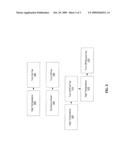
[0021]Before describing the invention in detail, it is useful to describe an example environment with which the invention can be implemented. FIG. 1 is a block diagram illustrating one possible configuration of a data storage system 100 that can serve as an example environment in which the present invention can be implemented.
[0022]The data storage system 100 may include multiple tape drives 102. These tape drives 102 might be in enclosures, such as enclosure 104. In various embodiments of the methods and systems described herein, the data storage system 100 might include two or more tape drives 102 and enclosures 104. Alternatively, in some embodiments, a large number of tape drives may be located in a single enclosure. The tape drive(s) and enclosure(s) may be located in a rack 106.
[0023]Figure illustrates a data storage system 100 that includes an array of twelve tape drives in twelve enclosures. This array is arranged in a stack six tape drives wide and 2 high. It will be understood, however, that many other possible arrangements are possible.
[0024]In some systems, each tape drive might include one or more fans, or other cooling devices to provide cooling. In other systems, fans may be located external to the tape drive 102. For example, the enclosures 104 or the rack 106 might include one or more fans to provide cooling. In some embodiments, fans might be included in the tape drive(s) 102 and the enclosure(s) 104. Generally, some of the fans that may be external to the tape drive may be controlled by the tape drive.
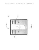
[0025]FIG. 2 is a diagram illustrating an example system in accordance with the systems and methods described herein. In various embodiments, the present invention provides systems and methods for cooling a data storage device. In accordance with some embodiments of the systems and methods described herein, a multiple data storage device enclosure 200 might include a first data storage device 202 and a second data storage device 204. Both data storage devices may be within the multiple data storage device enclosure 200. In some embodiments, the multiple data storage device enclosure 200 might be a drive sled enclosure or a chassis enclosure configured to contain tape drives, disk drives, other data storage devices or combinations of data storage devices.
[0026]In various embodiments, a first cooling device 206, external to the first and second data storage devices 202 and 204 may be coupled to the multiple data storage device enclosure 200. Additionally, in some embodiments, a controller 208 may be coupled to the cooling device 208 and configured to receive control signals from the first and second data storage devices 202 and 204.
[0027]Various embodiments of the systems and methods described herein may include a first data storage device 202 that transmits a signal to the controller 208 requesting cooling. In some embodiments, the first data storage device 202 may transmit a temperature. This temperature might be read by a temperature sensor and transmitted to the controller; the temperature sensor may be configured to determine the temperature of the first data storage device.
[0028]In accordance with some embodiments of the systems and methods described herein, the first data storage device 202 may transmit an on/off control signal to the controller 208. Based on this on/off control signal and the on/off control signal from, for example, other fans in the device 202, the controller might turn one or more fans on to provide cooling.
[0029]In some embodiments, the cooling device 206 might comprise a fan and the control signal may control the speed of the fan. For example, in some embodiments, rather than transmit an on/off signal from the data storage devices 202 and 204, a signal that indicates how hot the devices 202 and 204 are might be transmitted. In this way, the controller 208 might be able to speed up or slow down the cooling device based on how hot each device 202 and 204 is becoming in some embodiments, the controller might turn more fans on as the internal temperature of one or more of the devices 202 and 204 increases.
[0030]Some embodiments of the systems and methods described herein may comprise a second cooling device external to the first and second data storage devices and a first and a second temperature sensor. The first temperature sensor may be configured to measure the temperature of the first data storage device and the second temperature sensor may be configured to measure the temperature in the second data storage device. In some embodiments, both cooling devices may provide cooling to both data storage devices. In some embodiments, however, the first cooling device might provide more cooling to the first data storage device and the second cooling device might provide more cooling to the second data storage device.
[0031]In accordance with some embodiments of the systems and methods described herein, the controller may activate the cooling device associated with the warmer of the two data storage devices. Additionally, the controller may activate the fan associated with the cooler of the two data storage devices if the fan associated with the warmer of the two data storage devices does not provide adequate cooling for the system. Additionally, in some embodiments, the cooling devices may comprise fans. In various embodiments, the controller may be configured to control the speed of each fan based on the temperature of each data storage device and power consumption or contamination or noise. In some embodiments, the controller may turn on one of the two cooling devices when one of the two data storage devices is active and both cooling devices when both of the two data storage devices are active.
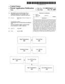
[0032]FIG. 3 is a chart illustrating several factors that might be considered when controlling a cooling device. In some embodiments, the controller 208 may be configured to control the fan based on the various factors. For example, these factors might include lowering noise, lowering power consumption, lowering contamination due to dust. In some embodiments, the number of fans running might be increased or decreased based on the temperature or other factors, for example, the other factors discussed.
[0033]For example, when temperature is high 300 inside a tape drive the tape drive might control a fan 302 that is external to the tape drive by sending a control signal external to the drive. In some embodiments of the systems and methods described herein, the fans might be turned on or off 306 in order to control excessive noise 304. For example, in racks including a large number of fans, if each fan is running, this may increase the noise in the room considerably. In many cases these fans might not all need to be running at the same time. Generally, if the number of fans running is decreased, the sound level may decrease.
[0034]In some embodiments, the controller 208 might consider the sound level and the temperature when determining the number of fans to turn on, the speed of the fans, etc. For example, a sound meter might be used to determine the level of sound. This information might be input into the controller 208. Temperature levels might also be input into the controller 208. These temperature levels might simply be an on/off signal from, for example, a tape drive. This on/off signal might be based on, for example, the internal temperature to a tape drive or other device.
[0035]In some embodiments, a high temperature 308 might cause a first fan to be turned on 310. If the high temperature continued 312, then a second fan might be turned on. In this way, the number of fans turned on might be increased or decreased based on the cooling needs of the system. In some embodiments, a temperature measurement might be transmitted to the controller. If the temperature reading is above a certain level, then both fans might be turned on. In other embodiments, for example, one fan might be turned on for each drive that is above a predetermined temperature. (Other ratios of fans to tape drives are also possible.)
[0036]Many different factors might be considered when determining to turn a cooling device on or off, or when determining how fast a cooling device should run based on the current state of a data storage system. In addition to temperature, noise, contamination and power consumption, a fan or other cooling device might be controlled based on other factors. For example, other factors might include room temperature in addition to internal temperature, expected future room or other temperature, current drive on/off state, expected future drive on/off state, power consumption of the devices being cooled, expected power consumption of the devices being cooled, noise from other devices in the area, noise from the device being cooled. In some embodiments, the number of fans running might also be controlled based on the presence of people in the room. For example, when people are in the room the noise generated might be a more important consideration.
[0037]For example, room temperature might be considered because cooler room air might cool better than warmer room air. Accordingly, fewer fans might be turned on or the speed of the fans might be decreased based on the air temperature.
[0038]In various other embodiments, an expected future temperature might be considered. For example, if the controller determines that several devices are about to turn off or other wise produce less heat, it might delay turning on a fan, for example, even if the device is warmer than a threshold temperature. In another example, a fan might be turned on because the temperature of a room is expected to rise. For example, during the day some rooms that might not be air conditioned might increase in temperature because the sun heats the room as the day progresses. Warm air might have less cooling ability. Accordingly, a cooling device might be turned on earlier to counter act this.
[0039]In some embodiments, fans might be controlled based on power consumption or expected power consumption. For example, power consumption can produce heat. The more power consumed, the more heat produced. Accordingly, as the power consumed increases the number of fans turned on might be increased, the speed of the fans might be increased, etc. Future data access might be known or predicted, accordingly, it might be possible to predict future power consumption and the cooling devices might be controlled based on this prediction.
[0040]As discussed above, noise might be a factor when considering to turn on a cooling device or determining the speed that such a device should run at. For example, the noise might be generated by the data storage devices or the noise might be generated by other devices in the room. In some embodiments, noise might be considered, for example, only when people are present. This might be based on when people are expected to be present, for example, normal work hours, or when people are actually present, based on some input indicating that people are present. This might be a logged on status on a computer, a motion sensor, etc.
[0041]In some embodiments, these various factors might be considered together. For example, power consumption might be considered in conjunction with room temperature. Through examining a particular data storage system, for example, the cooling required based on power consumption and room temperature might be determined. Other combinations might also be used, for example, room temperature, internal temperature and power consumption. For example, the room temperature might indicate the expected cooling ability of a given volume of air. Temperature might indicate a current need for cooling and power consumption might indicate how fast additional heat is entering the device or system. In this way a cooling level might be selected.
[0042]In some embodiments, a minimum cooling level might be selected. This might be done to conserve the energy used by the cooling devices or to minimize the noise. This might be controlled differently when people are working around the data storage devices.
[0043]While various embodiments of the present invention have been described above, it should be understood that they have been presented by way of example only, and not of limitation. Likewise, the various diagrams may depict an example architectural or other configuration for the invention, which is done to aid in understanding the features and functionality that can be included in the invention. The invention is not restricted to the illustrated example architectures or configurations, but the desired features can be implemented using a variety of alternative architectures and configurations. Indeed, it will be apparent to one of skill in the art how alternative functional, logical or physical partitioning and configurations can be implemented to implement the desired features of the present invention. Also, a multitude of different constituent module names other than those depicted herein can be applied to the various partitions. Additionally, with regard to flow diagrams, operational descriptions and method claims, the order in which the steps are presented herein shall not mandate that various embodiments be implemented to perform the recited functionality in the same order unless the context dictates otherwise.
[0044]Although the invention is described above in terms of various exemplary embodiments and implementations, it should be understood that the various features, aspects and functionality described in one or more of the individual embodiments are not limited in their applicability to the particular embodiment with which they are described, but instead can be applied, alone or in various combinations, to one or more of the other embodiments of the invention, whether or not such embodiments are described and whether or not such features are presented as being a part of a described embodiment. Thus, the breadth and scope of the present invention should not be limited by any of the above-described exemplary embodiments.
[0045]Terms and phrases used in this document, and variations thereof unless otherwise expressly stated, should be construed as open ended as opposed to limiting. As examples of the foregoing: the term "including" should be read as meaning "including, without limitation" or the like; the term "example" is used to provide exemplary instances of the item in discussion, not an exhaustive or limiting list thereof, the terms "a" or "an" should be read as meaning "at least one," "one or more," or the like; and adjectives such as "conventional," "traditional," "normal," "standard," "known" and terms of similar meaning should not be construed as limiting the item described to a given time period or to an item available as of a given time, but instead should be read to encompass conventional, traditional, normal, or standard technologies that may be available or known now or at any time in the future. Likewise, where this document refers to technologies that would be apparent or known to one of ordinary skill in the art, such technologies encompass those apparent or known to the skilled artisan now or at any time in the future.
[0046]A group of items linked with the conjunction "and" should not be read as requiring that each one of those items be present in the grouping, but rather should be read as "and/or" unless expressly stated otherwise. Similarly, a group of items linked with the conjunction "or" should not be read as requiring mutual exclusivity among that group, but rather should also be read as "and/or" unless expressly stated otherwise. Furthermore, although items, elements or components of the invention may be described or claimed in the singular, the plural is contemplated to be within the scope thereof unless limitation to the singular is explicitly stated.
[0047]The presence of broadening words and phrases such as "one or more," "at least," "but not limited to" or other like phrases in some instances shall not be read to mean that the narrower case is intended or required in instances where such broadening phrases may be absent. The use of the term "module" does not imply that the components or functionality described or claimed as part of the module are all configured in a common package. Indeed, any or all of the various components of a module, whether control logic or other components, can be combined in a single package or separately maintained and can further be distributed across multiple locations.
[0048]Additionally, the various embodiments set forth herein are described in terms of exemplary block diagrams, flow charts and other illustrations. As will become apparent to one of ordinary skill in the art after reading this document, the illustrated embodiments and their various alternatives can be implemented without confinement to the illustrated examples. For example, block diagrams and their accompanying description should not be construed as mandating a particular architecture or configuration.
User Contributions:
comments("1"); ?> comment_form("1"); ?>Inventors list |
Agents list |
Assignees list |
List by place |
Classification tree browser |
Top 100 Inventors |
Top 100 Agents |
Top 100 Assignees |
Usenet FAQ Index |
Documents |
Other FAQs |
User Contributions:
Comment about this patent or add new information about this topic:
Images included with this patent application:
 |  |
 |
| Similar patent applications: | |
| Date | Title |
|---|---|
| 2013-09-05 | Heat pump system for vehicle and method of controlling the same |
| 2013-08-29 | Power supply system for a vehicle climate control unit |
| 2013-08-08 | Heat storage device for an engine |
| 2013-08-22 | Heat recuperation device for an exhaust line |
| 2011-08-11 | System and method for moving a first fluid using a second fluid |
| New patent applications in this class: | |
| Date | Title |
|---|---|
| 2018-01-25 | Graphite laminates, processes for producing graphite laminates, structural object for heat transport, and rod-shaped heat-transporting object |
| 2016-06-23 | Crimping power module |
| 2016-06-16 | Method for the production of a cooling plate for a cooling device of a battery |
| 2016-06-09 | Cooling structure for electronic boards |
| 2016-06-09 | Partitioned cooling for electronic devices and systems |
| Top Inventors for class "Heat exchange" | |
| Rank | Inventor's name |
|---|---|
| 1 | Levi A. Campbell |
| 2 | Chun-Chi Chen |
| 3 | Tai-Her Yang |
| 4 | Robert E. Simons |
| 5 | Richard C. Chu |