Patent application title: NTC THERMISTOR CERAMIC AND NTC THERMISTOR USING THE SAME
Inventors:
Kiyohiro Koto (Higashiohmi-Shi, JP)
Assignees:
MURATA MANUFACTURING CO., LTD.
IPC8 Class: AH01C704FI
USPC Class:
338 22 R
Class name: Resistance value responsive to a condition current and/or voltage (e.g., ballast resistor) thermistor type
Publication date: 2009-07-16
Patent application number: 20090179732
having higher voltage resistance and a NTC
thermistor are provided. The NTC thermistor ceramic either contains
manganese and nickel, the manganese/nickel content ratio being is 87/13
to 96/4, or the manganese/cobalt content ratio being is 60/40 or more and
90/10 or less. The NTC thermistor ceramic includes a first phase, which
is a matrix, and a second phase composed of plate crystals dispersed in
the first phase, the second phase has an electrical resistance higher
than that of the first phase and a higher manganese content than the
first phase, and the first phase has a spinel structure. A NTC thermistor
includes a ceramic element body composed of the NTC thermistor ceramic
having the above-described features, internal electrode layers formed
inside the ceramic element body, and external electrode layers disposed
on two side faces of the ceramic element bodyClaims:
1. A NTC thermistor ceramic comprising:a first phase, which is a matrix,
and a second phase dispersed in the first phase, wherein the second phase
includes crystals having an average aspect ratio of at least about 3:1
and has an electrical resistance higher than that of the first phase.
2. A NTC thermistor ceramic comprising a first phase, which is a matrix, and a second phase dispersed in the first phase, wherein the second phase comprises plate crystals and has an electrical resistance higher than that of the first phase.
3. The NTC thermistor ceramic according to claim 2, wherein the first and second phases contain manganese, and the manganese content in the second phase is higher than that in the first phase.
4. The NTC thermistor ceramic according to claim 3, wherein the first phase has a spinel structure, the first and second phases contain manganese and nickel, and the atomic manganese/nickel content ratio of the NTC thermistor ceramic as a whole is 87/13 to 96/4, andthe NTC thermistor ceramic contains 0 at % to 15 at % copper, 0 at % to 10 at % aluminum, 0 at % to 10 at % iron, 0 at % to 15 at % cobalt, 0 at % to 5 at % titanium, and 0 at % to 1.5 at % zirconium.
5. The NTC thermistor ceramic according to claim 4, further comprising a third phase dispersed in the first phase,wherein the third phase is different from the second phase and has an electrical resistance higher than that of the first phase.
6. The NTC thermistor ceramic according to claim 5, wherein the third phase contains an alkaline earth metal.
7. The NTC thermistor ceramic according to claim 3, wherein the first phase has a spinel structure, the first and second phases contain manganese and cobalt, and the atomic manganese/cobalt content ratio of the NTC thermistor ceramic as a whole is 60/40 to 90/10, andthe NTC thermistor ceramic contains 0 at % to 22 at % copper, 0 at % to 15 at % aluminum, 0 at % to 15 at % iron, 0 at % to 15 at % nickel, and 0 at % to 1.5 at % zirconium.
8. The NTC thermistor ceramic according to claim 7, further comprising a third phase dispersed in the first phase, andthe third phase is different from the second phase and has an electrical resistance higher than that of the first phase.
9. The NTC thermistor ceramic according to claim 8, wherein the third phase contains an alkaline earth metal.
10. The NTC thermistor ceramic according to claim 1, wherein the first phase has a spinel structure, the first and second phases contain manganese and nickel, and the atomic manganese/nickel content ratio of the NTC thermistor ceramic as a whole is 87/13 to 96/4, andthe NTC thermistor ceramic contains 0 at % to 15 at % copper, 0 at % to 10 at % aluminum, 0 at % to 10 at % iron, 0 at % to 15 at % cobalt, and 0 at % to 5 at % titanium, and further contains at least one element selected from the group consisting of calcium and strontium, the calcium content being 10 at % or less (excluding 0 at %) and the strontium content being 5 at % or less (excluding 0 at %).
11. The NTC thermistor ceramic according to claim 10, wherein the first phase has a spinel structure, the first and second phases contain manganese and cobalt, and the atomic manganese/cobalt content ratio of the NTC thermistor ceramic as a whole is 60/40 to 90/10, andthe NTC thermistor ceramic contains 0 at % to 22 at % copper, 0 at % to 15 at % aluminum, 0 at % to 15 at % iron, and 0 at % to 15 at % nickel, and further contains at least one element selected from the group consisting of calcium and strontium, the calcium content being 5 at % or less (excluding 0 at %) and the strontium content being 5 at % or less (excluding 0 at %).
12. The NTC thermistor ceramic according to claim 1, further comprising a third phase dispersed in the first phase,wherein the third phase is different from the second phase and has an electrical resistance higher than that of the first phase.
13. The NTC thermistor ceramic according to claim 12, wherein the third phase contains an alkaline earth metal.
14. A NTC thermistor comprising a thermistor element body composed of the NTC thermistor ceramic according to claim 12 and an electrode disposed on a surface of the thermistor element body.
15. A NTC thermistor comprising a thermistor element body composed of the NTC thermistor ceramic according to claim 17 and an electrode disposed on a surface of the thermistor element body.
16. A NTC thermistor comprising a thermistor element body composed of the NTC thermistor ceramic according to claim 4 and an electrode disposed on a surface of the thermistor element body.
17. A NTC thermistor comprising a thermistor element body composed of the NTC thermistor ceramic according to claim 3 and an electrode disposed on a surface of the thermistor element body.
18. A NTC thermistor comprising a thermistor element body composed of the NTC thermistor ceramic according to claim 2 and an electrode disposed on a surface of the thermistor element body.
19. A NTC thermistor comprising a thermistor element body composed of the NTC thermistor ceramic according to claim 1 and an electrode disposed on a surface of the thermistor element body.Description:
[0001]This is a continuation-in-part of application Serial No.
PCT/JP2007/068136, filed Sep. 19, 2007.
TECHNICAL FIELD
[0002]The present invention generally relates to NTC thermistor ceramics and in particular to NTC thermistor ceramics suitable for use in a NTC thermistor for suppressing inrush current generated when a power switch is turned ON, and a NTC thermistor.
BACKGROUND ART
[0003]NTC thermistors known in the art have been roughly categorized into two types depending on the usage, and temperature-compensating thermistors and inrush current-limiting thermistor. Among these, inrush current-limiting NTC thermistors are mainly built into power circuits and used for limiting the large inrush current that instantaneously flows when the capacitors in the circuits start charge accumulation upon turning on the power source.
[0004]One example of the above-described NTC thermistors known in the art is a multilayer NTC thermistor shown in FIG. 3. In this multilayer NTC thermistor, for example, internal electrode layers 11 are embedded in a ceramic element body 20 having a negative resistance temperature characteristic and extend to be exposed in two end faces in an alternating manner. External electrodes 12 are formed on the two end faces of the ceramic element body 20 and are electrically connected to the exposed internal electrode layers 11.
[0005]Various thermistor ceramic compositions that contain metal oxides containing manganese (Mn) and nickel (Ni) as main components have been known as the material for the ceramic element body.
[0006]For example, Japanese Unexamined Patent Application Publication No. 62-11202 (Patent Document 1) describes a thermistor composition including an oxide containing three elements, namely, manganese, nickel, and aluminum, in which the ratios of these elements are within the ranges of 20 to 85 mol % manganese, 5 to 70 mol % nickel, and 0.1 to 9 mol % aluminum, the total of the three elements being 100 mol %.
[0007]Another example, Japanese Patent No. 3430023 (Patent Document 2), describes a thermistor composition in which 0.01 to 20 wt % cobalt oxide, 5 to 20 wt % copper oxide, 0.01 to 20 wt % iron oxide, and 0.01 to 5.0 wt % zirconium oxide are added to a metal oxide, containing, in terms of the content of the metals only, 50 to 90 mol % manganese and 10 to 50 mol % nickel totaling to 100 mol %.
[0008]Another example is Japanese Unexamined Patent Application Publication No. 2005-150289 (Patent Document 3) which describes a thermistor composition containing a manganese oxide, a nickel oxide, an iron oxide, and a zirconium oxide, in which a mol % (wherein a is 45 to 95 excluding 45 and 95) manganese oxide in term of Mn and (100-a) mol % nickel oxide in terms of Ni are contained as main components, and per 100 wt % of these main components, the ratios of the respective components are 0 to 55 wt % (excluding 0 wt % and 55 wt %) iron oxide in terms of Fe2O3 and 0 to 15 wt % (excluding 0 wt % and 15 wt %) zirconium oxide in terms of ZrO2.
[0009]Meanwhile, COUDERC J. J., BRIEU M., FRITSCH S, and ROUSSET A., DOMAIN MICROSTRUCTURE IN HAUSMANNITE Mn3O4 AND IN NICKEL MANGANITE, THIRD EURO-CERAMICS, VOL. 1 (1993) pp. 763-768 (Non-Patent Document 1) reports a thermistor ceramic composition in which plate-shaped deposits which are generated by gradually cooling Mn3O4 from high temperature (cooling rate: 6° C./hr) but not when Mn3O4 is rapidly cooled from high temperature in air, giving instead a lamella structure (stripe-shaped contrast structure). In addition, this document also reports that NiO0.75Mn2.25O4 forms a spinel single phase when gradually cooled from high temperature (cooling rate: 6° C./hr) in which no plate-shaped deposits or lamella structures are observed, and forms a lamella structure but not plate-shaped deposits when rapidly cooled from high temperature in air.
Patent Document 1: Japanese Unexamined Patent Application Publication No. 62-11202
Patent Document 2: Japanese Patent No. 3430023
Patent Document 3: Japanese Unexamined Patent Application Publication No. 2005-150289
[0010]Non-Patent Document 1: COUDERC J. J., BRIEU M., FRITSCH S, and ROUSSET A., DOMAIN MICROSTRUCTURE IN HAUSMANNITE Mn3O4 AND IN NICKEL MANGANITE, THIRD EURO-CERAMICS, VOL. 1 (1993) pp. 763-768
DISCLOSURE OF INVENTION
Problems to be Solved by the Invention
[0011]When thermistor ceramic compositions proposed in the above-described documents are used to make inrush current-limiting NTC thermistors, the insufficient dispersion of raw materials results in inhomogeneous dispersion of the compounds forming the ceramic, and a variation in ceramic grain diameters of the raw materials results in local formation of low-resistance regions in the thermistor element bodies of the resulting NTC thermistors. If current, such as inrush current, flows in such NTC thermistor element bodies (FIG. 10), the inrush current may concentrate on the low-resistance portions of the NTC thermistor element bodies, the temperature of the current-concentrated portions may rise, and the NTC thermistor element bodies may be melted by the heat. In other words, the existing thermistor ceramics may have insufficient voltage resistance depending on the manufacturing conditions, such as variation in ceramic grain diameters and insufficient dispersion of raw materials.
[0012]The documents described above report that different crystal structures can be derived from Mn3O4 and NiO0.75Mn2.25O4, i.e., the thermistor compositions, by changing the cooling rate from high temperature. However, the inventor of the present invention has found that none of the crystal structures of these compositions has sufficient voltage resistance.
[0013]An object of the present invention is to provide a NTC thermistor ceramic having excellent voltage resistance and a NTC thermistor.
Means for Solving the Problems
[0014]In order to attain the object described above, the inventor assumed that the fracture mode caused by inrush current is attributable to the thermal melting of and cracks in the NTC thermistor element bodies, and studied various compositions and crystal structures. As a result, the inventor has found that the voltage resistance can be enhanced when a different phase having a relatively high electrical resistance and containing plate crystals is dispersed in the matrix. The present invention has been made on the basis of this finding.
[0015]A NTC thermistor ceramic of this invention includes a first phase, which is a matrix, and a second phase dispersed in the first phase, in which the second phase includes plate crystals and has an electrical resistance higher than that of the first phase.
[0016]According to the NTC thermistor ceramic of this invention, the second phase composed of plate crystals having a higher electrical resistance than the first phase exists in the first phase, i.e., the matrix. The present inventor conducted extensive investigations and found that even when regions having a low electrical resistance are locally formed in a NTC thermistor ceramic mainly composed of Mn, the potential gradient that occurs in the matrix as a result of concentration of electrical current in the low-resistance regions during application of inrush current can be moderated by the presence of a dispersed high-electrical-resistance phase having a higher resistance than the matrix. As a result, the electrical field concentration on the low-resistance regions can be moderated, and fracture caused by heat melting of the thermistor element body can be suppressed. Thus, the voltage resistance of a NTC thermistor using the NTC thermistor ceramic of the present invention can be further improved.
[0017]In the NTC thermistor ceramic of the present invention, preferably, the first and second phases contain manganese and the manganese content in the second phase is higher than that in the first phase.
[0018]In this manner, the electrical resistance of the second phase can be made higher than that of the first phase. Thus, fracture caused by heat melting can be suppressed, and the voltage resistance of the NTC thermistor ceramic can be improved. Furthermore, since the main components of the first and second phases are the same, no complicated synthetic process is needed in depositing plate crystals, and strains and cracks are not readily generated since the it is easy to bond the first phase to the second phase.
[0019]According a NTC thermistor ceramic according to one aspect of the present invention, preferably, the first phase has a spinel structure, the first and second phases contain manganese and nickel, the (manganese content)/(nickel content) ratio of the NTC thermistor ceramic as a whole is or more and 96/4 or less, and the NTC thermistor ceramic contains 0 at % to 15 at % copper, 0 at % to 10 at % aluminum, 0 at % to 10 at % iron, 0 at % to 15 at % cobalt, 0 at % to 5 at % titanium, and 0 at % to 1.5 at % zirconium.
[0020]According to this aspect, a structure in which a high-resistance phase having a higher electrical resistance than the matrix exists in the matrix can be achieved, the hardness of the NTC thermistor ceramic can be increased, and the toughness can be improved. As a result, not only fracture caused by heat melting is suppressed but also fracture attributable to cracks can be suppressed. Thus, the voltage resistance of the NTC thermistor ceramic can be further improved.
[0021]Incorporating 10 at % or less aluminum, 10 at % or less iron, 15 at % or less cobalt, and 5 at % or less titanium further improves the hardness or fracture toughness of the NTC thermistor ceramic. Thus, fracture attributable to cracks can be suppressed further and the voltage resistance can be further improved.
[0022]Incorporating 1.5 at % or less zirconium allows zirconium oxide to segregate in the grain boundaries of the ceramic crystal grains and thus improves mechanical properties of the grain boundaries of the ceramic crystal grains composed of the NTC thermistor ceramic. Thus, fracture attributable to cracks can be suppressed, and the voltage resistance can be further improved as a result.
[0023]According to a NTC thermistor ceramic of another aspect of the present invention, preferably, the first phase has a spinel structure, the first and second phases contain manganese and cobalt, the (manganese content)/(cobalt content) ratio of the NTC thermistor ceramic as a whole is 60/40 or more and 90/10 or less, and the NTC thermistor ceramic contains 0 at % to 22 at % copper, 0 at % to 15 at % aluminum, 0 at % to 15 at % iron, 0 at % to 15 at % nickel, and 0 at % to 1.5 at % zirconium.
[0024]According to this aspect, a structure in which a high-resistance phase having a higher electrical resistance than the matrix exists in the matrix can be achieved, the hardness of the NTC thermistor ceramic can be increased, and the toughness can be improved. As a result, not only fracture caused by heat melting is suppressed but also fracture attributable to cracks can be suppressed. Thus, the voltage resistance of the NTC thermistor ceramic can be further improved.
[0025]Incorporating 15 at % or less aluminum, 15 at % or less iron, and 15 at % or less nickel further improves the hardness or fracture toughness of the NTC thermistor ceramic. Thus, fracture attributable to cracks can be suppressed further and the voltage resistance can be further improved.
[0026]Incorporating 1.5 at % or less zirconium allows zirconium oxide to segregate in the grain boundaries of the ceramic crystal grains and thus improves mechanical properties of the grain boundaries of the ceramic crystal grains composed of the NTC thermistor ceramic. Thus, fracture attributable to cracks can be suppressed, and the voltage resistance can be further improved as a result.
[0027]The NTC thermistor ceramic of the present invention having any one of the features described above preferably further includes a third phase different from the second phase dispersed in the first phase, and the third phase preferably has an electrical resistance higher than that of the first phase.
[0028]In this manner, a third phase having an electrical resistance higher than that of the first phase exists in the first phase, i.e., in addition to the matrix and the second phase composed of plate crystals and having a higher electrical resistance than the first phase. Since another high-resistance phase different from the first high-resistance phase composed of plate crystals exists in the matrix, the potential gradient in the matrix can be decreased and local electrical field concentration can be moderated when excessive inrush current is applied. Thus, fracture caused by heat melting can be suppressed. The voltage resistance of the NTC thermistor ceramic can be increased.
[0029]Increasing the copper content in pursuing further improvements in voltage resistance sometimes generates cracks and the like during firing. However, the resistivity of the material at room temperature, at a low copper content, tends to be high. The invention having the above-described features can lower the resistivity at room temperature while maintaining high voltage resistance.
[0030]In such a case, the third phase preferably contains an alkaline earth element.
[0031]In the composition constituting the NTC thermistor ceramic of the present invention having the above-described features, preferably, the first phase has a spinel structure, the first and second phases contain manganese and nickel, the (manganese content)/(nickel content) ratio of the NTC thermistor ceramic as a whole is 87/13 or more and 96/4 or less, and the NTC thermistor ceramic contains 0 at % to at % copper, 0 at % to 10 at % aluminum, 0 at % to 10 at % iron, 0 at % to 15 at % cobalt, and 0 at % to 5 at % titanium, and further contains, as the alkaline earth metal, at least one element selected from the group consisting of calcium and strontium, the calcium content being 10 at % or less (excluding 0 at %) and the strontium content being 5 at % or less (excluding 0 at %).
[0032]In another composition constituting the NTC thermistor ceramic of the present invention having the above-described features, the first phase has a spinel structure, the first and second phases contain manganese and cobalt, the (manganese content)/(cobalt content) ratio of the NTC thermistor ceramic as a whole is 60/40 or more and 90/10 or less, and the NTC thermistor ceramic contains 0 at % to 22 at % or less copper, 0 at % to 15 at % aluminum, 0 at % to 15 at % iron, and 0 at % to 15 at % nickel, and further contains, as the alkaline earth element, at least one element selected from the group consisting of calcium and strontium, the calcium content being 5 at % or less (excluding 0 at %) and the strontium content being 5 at % or less (excluding 0 at %).
[0033]In this manner, the voltage resistance of the NTC thermistor ceramic can be further improved, and a structure having a low electrical resistivity at room temperature can be achieved.
[0034]A NTC thermistor according to the present invention includes a thermistor element body composed of the NTC thermistor ceramic having any of the features described above and an electrode disposed on a surface of the thermistor element body.
[0035]In this manner, a NTC thermistor with high voltage resistance suitable for limiting high inrush current can be achieved.
ADVANTAGES
[0036]According to this invention, the voltage resistance of the NTC thermistor ceramic can be improved, and a NTC thermistor with high voltage resistance suitable for limiting high inrush current can be made using this NTC thermistor ceramic.
BRIEF DESCRIPTION OF DRAWINGS
[0037]FIG. 1 is a diagram for explaining how to calculate specific resistance in EXAMPLES.
[0038]FIG. 2 is a photograph of ceramic crystal grains of a NTC thermistor ceramic which is one example of the present invention observed with a scanning ion microscope.
[0039]FIG. 3 is a cross-sectional view showing a structure of a multilayer NTC thermistor prepared in EXAMPLES.
[0040]FIG. 4 is a graph showing the relationship between the inrush current value and rate of change in electrical resistance ΔR25 of multilayer NTC thermistors prepared from several compositions of EXAMPLES 1B and 2A.
[0041]FIG. 5 is a graph showing the relationship between the inrush current value and rate of change in electrical resistance ΔR25 of multilayer NTC thermistors prepared from several compositions of EXAMPLE 3A.
[0042]FIG. 6 is a graph showing the relationship between the inrush current value and rate of change in electrical resistance ΔR25 of multilayer NTC thermistors prepared from several compositions of EXAMPLE 4A.
[0043]FIG. 7 is another graph showing the relationship between the inrush current value and rate of change in electrical resistance ΔR25 of multilayer NTC thermistors prepared from several compositions of EXAMPLE 4A.
[0044]FIG. 8 is another graph showing the relationship between the inrush current value and rate of change in electrical resistance ΔR25 of multilayer NTC thermistors prepared from several compositions of EXAMPLE 4A.
[0045]FIG. 9 is another graph showing the relationship between the inrush current value and rate of change in electrical resistance ΔR25 of multilayer NTC thermistors prepared from several compositions of EXAMPLE 4A.
[0046]FIG. 10 is another graph showing the relationship between the inrush current value and rate of change in electrical resistance ΔR25 of multilayer NTC thermistors prepared from several compositions of EXAMPLE 4A.
[0047]FIG. 11 is a graph showing the relationship between the inrush current value and rate of change in electrical resistance ΔR25 of multilayer NTC thermistors prepared from several compositions of EXAMPLE 5A.
[0048]FIG. 12 is another graph showing the relationship between the inrush current value and rate of change in electrical resistance ΔR25 of multilayer NTC thermistors prepared from several compositions of EXAMPLE 5A.
[0049]FIG. 13 is another graph showing the relationship between the inrush current value and rate of change in electrical resistance ΔR25 of multilayer NTC thermistors prepared from several compositions of EXAMPLE 5A.
[0050]FIG. 14 is another graph showing the relationship between the inrush current value and rate of change in electrical resistance ΔR25 of multilayer NTC thermistors prepared from several compositions of EXAMPLE 5A.
[0051]FIG. 15 is a graph showing the relationship between the inrush current value and rate of change in electrical resistance ΔR25 of multilayer NTC thermistors prepared from several compositions of EXAMPLE 6A.
[0052]FIG. 16 is another graph showing the relationship between the inrush current value and rate of change in electrical resistance ΔR25 of multilayer NTC thermistors prepared from several compositions of EXAMPLE 6A.
[0053]FIG. 17 is another graph showing the relationship between the inrush current value and rate of change in electrical resistance ΔR25 of multilayer NTC thermistors prepared from several compositions of EXAMPLE 6A.
[0054]FIG. 18 is another graph showing the relationship between the inrush current value and rate of change in electrical resistance ΔR25 of multilayer NTC thermistors prepared from several compositions of EXAMPLE 6A.
[0055]FIG. 19 is a graph showing the relationship between the inrush current value and rate of change in electrical resistance ΔR25 of multilayer NTC thermistors prepared from several compositions of EXAMPLE 7A.
[0056]FIG. 20 is a graph showing the relationship between the inrush current value and rate of change in electrical resistance ΔR25 of multilayer NTC thermistors prepared from several compositions of EXAMPLE 8A.
[0057]FIG. 21 is a graph showing the relationship between the inrush current value and rate of change in electrical resistance ΔR25 of multilayer NTC thermistors prepared from several compositions of EXAMPLE 9A.
[0058]FIG. 22 is a photograph of ceramic crystal grains of a NTC thermistor ceramic which is another example of the present invention observed with a scanning ion microscope.
REFERENCE NUMERALS
[0059]1: NTC thermistor, 11: internal electrode layer, 12: external electrode layer, 20: ceramic element body
BEST MODES FOR CARRYING OUT THE INVENTION
[0060]The present inventor has made the following investigations on the reason why the voltage resistance of existing NTC thermistor ceramics is insufficient:
(1) First, the inventor assumed that the fracture mode caused by excessive inrush current is attributable to thermal melting as one of the reasons for insufficient voltage resistance. When the temperature of a NTC thermistor rises, its electrical resistance decreases. For example, when disintegration of the raw materials is insufficient and compounds forming the ceramic are dispersed inhomogeneously or when the ceramic grain diameters of the raw materials have a variation, the NTC thermistor ceramic may locally have portions with a low electrical resistance. When an inrush current is applied to such a NTC thermistor, the inrush current concentrates on portions with low electrical resistance, thereby raising the temperature of those portions. As a result, the electrical resistance of those portions becomes lower than the electrical resistance of other portions, and this promotes further concentration of electrical current. Consequently, electrical current concentrates on one region, further elevating the temperature and melting the ceramic constituting the thermistor element body, and the melted portion becomes a starting point of the fracture.
[0061]A NTC thermistor ceramic of the present invention contains, in its matrix, a phase composed of plate crystals and having a high electrical resistance relative to the matrix. Simulation results by finite element analysis have shown that according to this structure, the potential gradient in the matrix decreases when inrush current is applied. Based on these results, it has been found that presence of a high-resistance phase having a high resistance relative to the matrix moderates the local electrical field concentration in the matrix and suppresses fracture caused by thermal melting.
(2) Next, the inventor assumed that the fracture mode caused by inrush current is attributable to cracks as another reason for insufficient voltage resistance. The ceramic constituting a NTC thermistor ceramic undergoes thermal expansion with an increase in temperature. Thus, the ceramic is required to exhibit a strength that can withstand the thermal expansion in order to enhance the voltage resistance.
[0062]According to one embodiment of the present invention, the first phase has a spinel structure, the first and second phases contain manganese and nickel, and the (manganese content)/(nickel content) ratio of the NTC thermistor ceramic as a whole is 87/13 or more and 96/4 or less. The experiments conducted by the inventor have shown that a composition having a high hardness or a high fracture toughness can be obtained as the (manganese content)/(nickel content) ratio becomes higher. Based on these results, it is assumed that increasing the manganese content helps achieve a high hardness or a high fracture toughness and suppress fracture caused by cracks.
[0063]The first phase has a spinel structure, the first and second phases contain manganese and nickel, the (manganese content)/(nickel content) ratio of the NTC thermistor ceramic as a whole is 87/13 or more and 96/4 or less, the NTC thermistor ceramic contains 0 at % to 15 at % copper, 0 at % to 10 at % aluminum, 0 at % to 10 at % iron, 0 at % to 15 at % cobalt, 0 at % to 5 at % titanium, and 0 at % to 1.5 at % zirconium, and the manganese content in the second phase is higher than that of the first phase.
[0064]The basic structure of the NTC thermistor ceramic according to another preferred embodiment of the present invention includes a first phase which is a matrix having a spinel structure and a second phase dispersed in the first phase and composed of a plurality of plate crystals, in which the second phase shows a higher electrical resistance than the first phase, the first and second phases contain manganese and cobalt, the (manganese content)/(cobalt content) ratio of the NTC thermistor ceramic as a whole is or more and 90/10 or less, and the manganese content in the second phase is higher than that of the first phase.
[0065]The first phase has a spinel structure, the first and second phases contain manganese and cobalt, the (manganese content)/(cobalt content) ratio of the NTC thermistor ceramic as a whole is 60/40 or more and 90/10 or less, the NTC thermistor ceramic contains 0 at % to 22 at % copper, 0 at % to 15 at % aluminum, 0 at % to 15 at % iron, 0 at % to 15 at % nickel, and 0 at % to 1.5 at % zirconium, and the manganese content in the second phase is higher than that of the first phase.
[0066]A NTC thermistor ceramic of any embodiment of the present invention preferably further includes a third phase different from the second phase dispersed in the first phase, the third phase preferably has an electrical resistance higher than that of the first phase, and the third phase preferably contains an alkaline earth metal. In such a case, preferably, the NTC thermistor ceramic contains as an alkaline earth metal at least one element selected from the group consisting calcium and strontium, the calcium content is preferably in the range of 10 at % or less (excluding 0 at %) in a system containing manganese and nickel as main components or in the range of 5 at % or less (excluding 0 at %) in a system containing manganese and cobalt as main components, and the strontium content is preferably in the range of 5 at % or less (excluding 0 at %).
[0067]Although the first phase of the NTC thermistor ceramic according to the embodiment of the present invention described above has a spinel structure, compositions having structures other than the spinel structure can have structures that exhibit high voltage resistance. The first phase is thus not limited to one having a spinel structure. Furthermore, although the NTC thermistor ceramic of the embodiment of the present invention includes a second phase composed of plate crystals, the form of crystals is not limited. The second phase has an effect of increasing the voltage resistance if crystals having certain aspect ratios, such as plate and needle crystals, are dispersed in the first phase and the electrical resistance of the second phase is higher than that of the first phase. Such crystals have an average aspect ratio (long axis/short axis) of at least about 3:1 in the figure projected from three dimension to two dimension. Moreover, the NTC thermistor ceramic of the present invention may contain inevitable impurities such as sodium.
EXAMPLES
[0068]Examples of preparation of NTC thermistors of the present invention will now be described.
Example 1A
[0069]Manganese oxide (Mn3O4) and nickel oxide (NiO) were weighed and blended so that the atomic ratios (atom %) of the manganese (Mn) and nickel (Ni) after firing were adjusted to ratios indicated in Table 1. To the resulting mixture, poly(ammonium carboxylate) serving as a dispersant and pure water were added, and the resulting mixture was disintegrated by wet-mixing in a ball mill, i.e., a mixer and a disintegrator, for several hours. The resulting mixture powder was dried and calcined for 2 hours at a temperature of 650° C. to 1000° C. To the calcined powder, the dispersant and pure water were again added and the resulting mixture was disintegrated by wet-mixing in a ball mill for several hours. To the resulting mixture powder, a water-based binder resin, i.e., an acrylic resin, was added, and the resulting mixture was defoamed in a low vacuum of 500 to 1000 mHg to prepare a slurry. The slurry was formed by the doctor blade method on a carrier film constituted by a polyethylene terephthalate (PET) film and dried to prepare a green sheet 20 to 50 μm in thickness on the carrier film.
[0070]In the example described above, a ball mill was used as a mixer and an integrator. Alternatively, an attritor, a jet mill, and various other disintegrators may be used. For the method for forming the green sheet, pulling methods such as lip coating and roll coating may be used other than the doctor blade method.
[0071]The obtained green sheet was cut to a predetermined size, and a plurality of sheets were stacked to a certain thickness. Subsequently, the sheets were pressed at about 106 Pa to prepare a multilayer green sheet compact.
[0072]The compact was cut into a predetermined shape and heated at a temperature of 300° C. to 600° C. for 1 hour to remove the binder. Then the compact was fired in the firing step described below to prepare a ceramic element body that served as the NTC thermistor ceramic of the present invention.
[0073]The firing step included a temperature-elevating process, a high temperature-retaining process, and a temperature-decreasing process. In the high temperature-retaining process, a temperature of 1000° C. to 1200° C. was maintained for 2 hours, and the temperature-elevating rate was 200° C./hour. The rate of temperature-decreasing was also 200° C./hour except when the temperature was in the range of 500° C. to 800° C. when it was about 1/2 of that temperature-decreasing rate. Plate crystals mainly composed of manganese oxide constituting a high-resistance second phase of the NTC thermistor ceramic of the present invention can be produced by decreasing the temperature-decreasing rate when the temperature is in the range of 800° C. to 500° C. to a level lower than that in other temperature ranges in the firing step. X-ray diffraction analysis (XRD) has found that plate crystals mainly composed of manganese oxide start to form in the temperature range of 700° C. to 800° C. in the temperature-decreasing process, and the number of crystals produced increases during the temperature-decreasing process down to 500° C. Moreover, gradual cooling (6° C./hour, requiring about 8.3 days) described in the prior art documents is not needed in the present invention, and the temperature-decreasing time can be about several hours, which is efficient. The firing atmosphere was air. The firing atmosphere may be oxygen gas.
[0074]Silver (Ag) electrodes were applied on both surfaces of the NTC thermistor element body and baked at 700° C. to 800° C. The resulting product was diced into a 1 mm2 size to prepare a single plate-type NTC thermistor shown in FIG. 1, which was used as an evaluation sample.
[0075]The electrical characteristics of each sample of the single plate-type NTC thermistor with electrodes were measured by a DC four-terminal method (Hewlett Packard 3458A multimeter).
[0076]In Table 1, "ρ25" indicates the resistivity (Ωcm) at a temperature of 25° C., calculated from the equation below where R25 (Ω) is the electrical resistance at 25° C. when current I (A) flows in the length direction of a sample having a width W (cm), a length L (cm), and a thickness T (cm) as shown in FIG. 1:
ρ25=R25×W×T/L
[0077]"B25/50" (K) is calculated from the equation below,
[0078]where R25 (Ω) is the electrical resistance at a temperature of 25° C. and R50 (Ω) is the electrical resistance at a temperature of 50° C.:
B25/50=(log R25-log R50)/(1/(273.15+25)-1/(273.15+50))
[0079]The results of the measurements on the NTC thermistors having ceramic element bodies containing manganese and nickel are shown in Table 1.
[0080]The voltage resistance of each sample of the NTC thermistor that includes a ceramic element body containing manganese and nickel as main metal elements was evaluated as follows. After the ceramic element body formed as a single plate was mounted on a substrate, leads were attached to the electrodes on the ceramic element body and a predetermined voltage was applied thereto to supply inrush current. Changes in electrical resistance at that time were measured. An ISYS low-temperature voltage resistance tester (model IS-062) was used as the measurement instrument.
[0081]As the inrush current flows into the NTC thermistor, the electrical resistance starts to increase rapidly after a certain current value is attained. Having high voltage resistance means that the electrical resistance does not change until a high current value is reached. In this example, the rate of change in electrical resistance ΔR25 when 10 A current was supplied to a NTC thermistor having a thickness of 0.65±0.05 mm was calculated to evaluate voltage resistance.
[0082]In Table 1, "voltage resistance" (%) is calculated by the equation below where R025 (Ω) is the electrical resistance at a temperature of 25° C. before supplying the inrush current, and R125 (Ω) is the electrical resistance at 25° C. after supplying 10 A inrush current:
ΔR25=(R125/R025-1)×100
TABLE-US-00001 TABLE 1 Mn Ni Voltage atom atom ρ25 B25/ resistance Plate No. % % Ωcm 50 K % crystal Judgment 101 80 20 1920 3960 39 No X 102 84 16 2334 3920 29 No X 103 87 13 17600 4215 -1 Yes ◯ 104 90 10 26890 4243 -0.5 Yes ◯ 105 93 7 80473 4375 0.4 Yes ◯ 106 96 4 269383 4583 -0.5 Yes ◯
[0083]As shown in Table 1, it was confirmed that in all samples of single plate-type NTC thermistors having ceramic element bodies containing manganese and nickel as the main metal elements, plate crystals mainly composed of manganese oxide serving as the second phase having a high electrical resistance were dispersed in the first phase, i.e., the matrix having a high electrical resistance, when the atomic (manganese content)/(nickel content) ratio was in the range of 87/13 or more and 96/4 or less. In the "judgment" column of Table 1, samples in which generation of the second phase was observed are marked by circles and samples in which generation of the second phase was not observed are marked by X. It was found that sample Nos. 103 to 106 in which generation of the second phase was observed exhibited a "rate of change in electrical resistance ΔR25 after application of inrush current", i.e., the indicator of the voltage resistance, of 10% or less and thus had high voltage resistance.
Example 1B
[0084]Manganese oxide (Mn3O4), nickel oxide (NiO), and copper oxide (CuO) were weighed and blended so that the atomic ratios (atom %) of the manganese (Mn), nickel (Ni), and copper (Cu) after firing were adjusted to ratios shown in Table 2. Then green sheets were prepared as in EXAMPLE 1A.
[0085]The resulting green sheets were stacked, pressed, and fired as in EXAMPLE 1A to prepare a ceramic element body that served as the NTC thermistor ceramic of the present invention. Electrodes were formed on the ceramic main body as in EXAMPLE 1A to obtain a NTC thermistor.
[0086]The voltage resistance of each sample of a single plate-type NTC thermistor including a ceramic element body containing manganese, nickel, and copper as main metal elements prepared as above was evaluated as follows. After the ceramic element body formed as a single plate was mounted on a substrate, leads were attached to the electrodes on the ceramic element body and a predetermined voltage was applied thereto to supply inrush current. Changes in electrical resistance at that time were measured. An ISYS low-temperature voltage resistance tester (model IS-062) was used as the measurement instrument.
[0087]As the inrush current flows into the NTC thermistor, the electrical resistance starts to increase rapidly after a certain current value. Having high voltage resistance means that the electrical resistance does not change until a high current value is reached. In this example, the rate of change in electrical resistance ΔR25 when 10 A current is supplied to a NTC thermistor having a thickness of 0.65±0.05 mm was calculated to evaluate voltage resistance.
[0088]In Table 2, "ΔR25 after application of inrush current" (%) is calculated by the equation below where R025 (Ω) is the electrical resistance at a temperature of 25° C. before supplying the inrush current, and R125 (Ω) is the electrical resistance at 25° C. after supplying 10 A inrush current:
ΔR25=(R125/R025-1)×100
[0089]In order to evaluate the reliability of the electrical resistance, the same type of NTC thermistor as above was used and the rate of change in electrical resistance ΔR25 after 100 cycles of heat test, each cycle including retaining at -55° C. for 30 minutes and at 125° C. for 30 minutes, was measured. The rate of change in electrical resistance ΔR25 is indicated as "reliability ΔR25" (%) in the table. The "reliability ΔR25" (%) is calculated by the following equation where R025 (Ω) is the electrical resistance at a temperature of 25° C. before the heat cycle test, and R225 (Ω) is the electrical resistance at 25° C. after the heat cycle test:
ΔR25=(R225/R025-1)×100
[0090]In the "judgment" column of Table 2, samples having "ΔR25 after application of inrush current" of 10% or less and "reliability ΔR25" of 20% or less are marked by circles while other samples are marked by X.
[0091]Vickers's hardness was measured with AKASHI MICRO HARDNESS TESTER (model MVK-E). In Table 2, Vickers's hardness Hv and fracture toughness KIc are indicated.
TABLE-US-00002 TABLE 2 Feed amounts of Electrical Voltage resistance Vickers raw materials characteristics ΔR25% after hardness Composition Mn/Ni Mn Ni Cu ρ25 application of Klc Reliability No. ratio atom % atom % atom % Ωcm B25/50 K inrush current Hv MN/m1.5 ΔR25% Plate crystal Judgment 107 73/27 69.7 25.8 4.5 178 3249 523 620 1.50 5.6 No X 108 77/23 73.5 22.0 4.5 146 3329 323 644 1.69 13.0 No X 109 80/20 76.4 19.1 4.5 171 3407 51 649 2.44 9.3 No X 110 85/15 81.2 14.3 4.5 152 3220 24 627 3.04 10.1 No X 111 79.9 14.1 6.0 84 3084 76 645 2.46 13.9 No X 112 87/13 74.0 11.0 15.0 102 2766 4 684 2.55 12.3 Yes ◯ 113 90/10 86.0 9.5 4.5 1220 3212 3 621 3.09 12.9 Yes ◯ 114 84.6 9.4 6.0 707 3058 6 637 2.73 14.6 Yes ◯ 115 81.5 9.0 9.5 218 2818 3 720 2.63 16.6 Yes ◯ 116 80.1 8.9 11.0 152 2760 2 680 2.54 14.0 Yes ◯ 117 78.8 8.7 12.5 174 2730 5 682 2.18 17.5 Yes ◯ 118 76.5 8.5 15.0 67 2809 7 717 2.37 14.8 Yes ◯ 119 95/5 84.6 4.4 11.0 306 2665 2 634 2.91 10.7 Yes ◯ 120 80.8 4.2 15.0 423 2679 3 661 2.64 8.0 Yes ◯ 121 96/4 81.6 3.4 15.0 513 2768 6 674 2.61 9.4 Yes ◯ 122 100/0 66.7 0 33.3 229 2889 24 350 1.70 12.0 No X
[0092]As shown in Table 2, it was confirmed that all samples that exhibited high voltage resistance, i.e., "ΔR25 after application of inrush current" of 10% or less, in evaluation of the voltage resistance had an atomic (manganese content)/(nickel content) ratio in the range of 87/13 or more and 96/4 or less.
[0093]These results indicate that when a NTC thermistor ceramic contains manganese and nickel and the (manganese content)/(nickel content) ratio is 87/13 or more and 96/4 or less, a structure is realized in which a high-resistance phase having a high resistance relative to a matrix is present in the matrix, and the hardness or the fracture toughness of the composition can be further enhanced. This not only moderates the electrical current concentration in the first phase and suppresses fracture caused by heat melting but also limits fracture caused by cracks. Thus, the voltage resistance of the NTC thermistor ceramic can be further improved. Moreover, it is shown that a NTC thermistor ceramic designed to contain 15 at % or less copper can realize a structure capable of improving the voltage resistance of the NTC thermistor ceramic.
[0094]Next, composition No. 116 was analyzed with a scanning ion microscope (SIM) and a scanning transmission electron microscope (STEM) to observe ceramic grains and conduct energy dispersive X-ray fluorescent spectrometry (EDX).
[0095]FIG. 2 is a photograph of ceramic grains observed with a scanning ion microscope. In FIG. 2, dispersed matter in the form of black lines is the plate crystals serving as the second phase.
[0096]According to the results of energy dispersive X-ray fluorescent spectrometry, the first phase, i.e., the matrix, contained 68.8 to 75.5 at % manganese, 11.3 to 13.7 at % nickel, and 13.1 to 19.9 at % copper, and the second phase composed of plate crystals and having a high resistance contained 95.9 to 97.2 at % manganese, 0.6 to 1.2 at % nickel, and 2.1 to 3.0 at % copper. These results show that the manganese content in the second phase is higher than that in the first phase. Although this slightly depends on the contents of other additives, the results show that the second phase contains 1.2 times as much manganese as the first phase in terms of atomic percent.
[0097]The electrical resistance of the first and second phases was directly measured by analysis using a scanning probe microscope (SPM). As a result, it was found that the electrical resistance of the second phase was higher than that of the first phase and was at least 10 times larger than the electrical resistance of the first phase.
Example 2a
[0098]Manganese oxide (Mn3O4), nickel oxide (NiO), copper oxide (CuO), aluminum oxide (Al2O3), iron oxide (Fe2O3), cobalt oxide (CO3O4), and titanium oxide (TiO2) were weighed and blended so that the atomic ratios (atom %) of manganese (Mn), nickel (Ni), copper (Cu), aluminum (Al), iron (Fe), cobalt (Co), and titanium (Ti) after firing were adjusted to ratios shown in Table 3. Then green sheets were prepared as in EXAMPLE 1A.
[0099]The resulting green sheets were stacked, pressed, and fired as in EXAMPLE 1A to prepare a ceramic element body serving as the NTC thermistor ceramic of the present invention. Electrodes were formed on the ceramic main body as in EXAMPLE 1A to obtain a NTC thermistor.
[0100]The electrical characteristics, voltage resistance, and reliability of each sample of the single plate-type NTC thermistor were evaluated as in EXAMPLE 1B. The results are shown in Table 3.
TABLE-US-00003 TABLE 3 Voltage Vickers Feed amounts of raw materials Electrical resistance hardness Mn/ Mn Ni Cu Al Fe Co Ti characteristics ΔR25% after Klc Re- Composition Ni atom atom atom atom atom atom atom ρ25 B25/ application of MN/ liability Plate No. ratio % % % % % % % Ωcm 50 K inrush current Hv m1.5 ΔR25% crystal Judgment 123 85/15 76.5 13.5 5.0 5.0 0 0 0 200 3219 51 679 2.87 8.5 No X 124 75.7 13.3 6.0 5.0 0 0 0 113 3097 42 682 2.51 8.9 No X 125 90/10 81.9 9.1 7.0 2.0 0 0 0 583 2960 -3 652 2.70 13.9 Yes ◯ 126 78.8 8.7 7.5 5.0 0 0 0 300 2900 0 753 2.61 0.6 Yes ◯ 127 77.4 8.6 9.0 5.0 0 0 0 288 2843 -5 659 2.37 13.8 Yes ◯ 128 77.0 8.5 7.5 7.0 0 0 0 103 2815 9 796 2.57 7.0 Yes ◯ 129 75.6 8.4 9.0 7.0 0 0 0 52 2731 -2 778 2.25 7.5 Yes ◯ 130 74.3 8.2 7.5 10.0 0 0 0 152 2947 6 774 2.66 5.4 Yes ◯ 131 72.9 8.1 9.0 10.0 0 0 0 70 2817 6 818 2.82 4.5 Yes ◯ 132 69.8 7.7 7.5 15.0 0 0 0 390 3119 20 848 2.17 4.4 No X 133 78.8 8.7 7.5 0 5.0 0 0 688 2828 5 689 2.47 6.7 Yes ◯ 134 77.4 8.6 9.0 0 5.0 0 0 510 2746 -3 708 2.13 8.2 Yes ◯ 135 75.2 8.3 6.5 0 10.0 0 0 3962 3150 8 727 2.18 12.0 Yes ◯ 136 70.7 7.8 6.5 0 15.0 0 0 8919 3284 16 767 1.77 15.1 No X 137 69.8 7.7 7.5 0 15.0 0 0 3452 3112 34 719 1.5 15.3 No X 138 78.8 8.7 7.5 0 0 5.0 0 491 3022 -1 659 2.70 8.0 Yes ◯ 139 77.4 8.6 9.0 0 0 5.0 0 330 2939 -7 677 2.16 8.5 Yes ◯ 140 75.6 8.4 6.0 0 0 10.0 0 615 3150 -3 677 3.23 13.1 Yes ◯ 141 74.3 8.2 7.5 0 0 10.0 0 356 3049 1 664 2.72 14.3 Yes ◯ 142 71.1 7.9 6.0 0 0 15.0 0 406 3146 2 680 2.53 11.1 Yes ◯ 143 69.8 7.7 7.5 0 0 15.0 0 210 3082 5 684 2.85 11.2 Yes ◯ 144 78.8 8.7 7.5 0 0 0 5.0 964 2888 6 619 3.03 15.3 Yes ◯ 145 77.4 8.6 9.0 0 0 0 5.0 574 2851 7 631 2.96 12.4 Yes ◯ 146 74.3 8.2 7.5 0 0 0 10.0 4058 3182 46 626 2.35 15.5 No X 147 96/4 80.6 3.4 11.0 5.0 0 0 0 954 2706 -6 701 2.23 8.8 Yes ◯
[0101]As shown in Table 3, among all samples of NTC thermistors, composition Nos. 123 and 124 have an atomic (manganese content)/(nickel content) ratio of 85/15, which is less than 87/13, and thus the second phase having a high electrical resistance, i.e., plate crystals mainly composed of manganese oxide, was not observed. Composition Nos. 125 to 146 having an atomic ratio of 90/10 and composition No. 147 having an atomic ratio of 96/4 satisfy the range of 87/13 or more and 96/4 or less. When these samples contained 15 at % or less copper, and 10 at % or less aluminum, 10 at % or less iron, 15 at % or less cobalt, or 5 at % or less titanium, dispersion of plate-shaped manganese oxide crystals serving as the second phase having a high electrical resistance was confirmed in the first phase, i.e., the matrix having a low electrical resistance. Thus, not only the electrical current concentration in the first phase is moderated and fracture caused by heat melting is suppressed but also the hardness or fracture toughness of the NTC thermistor ceramic can be enhanced. Thus, fracture attributable to cracks can be suppressed, and the voltage resistance can be improved as a result.
Example 2B
[0102]Green sheets obtained in EXAMPLE 2A were punched out or cut into a particular size, and internal electrode pattern layers were formed on a predetermined number of sheets by a screen printing method. The electrode-forming paste used to form the internal electrode pattern layers could be a conductive paste mainly composed of a noble metal, such as silver, silver-palladium, gold, platinum, or the like, or a base metal, such as nickel. In this example, a silver-palladium conductive paste with a silver/palladium content ratio of 3/7 was used.
[0103]The green sheets with the internal electrode pattern layers formed thereon were stacked so that the internal electrode pattern layers were alternately exposed, and green sheets with no internal electrode pattern layers were provided as the outermost layers. The resulting green sheets were pressed to form a multilayer green sheet compact.
[0104]The compact was fired as in EXAMPLE 1A to form a ceramic element body which was the constitutional component of the NTC thermistor of the present invention.
[0105]Subsequently, the outer shape of the ceramic element body was finished by barrel polishing, and an external electrode-forming paste was applied on two side faces of the ceramic element body. The electrode-forming paste used could be a paste mainly composed of a noble metal, such as silver, silver-palladium, gold, platinum, or the like. In this example, a silver paste was used. The silver paste was applied and baked at 700° C. to 850° C. to form the external electrodes. Finally, nickel and tin were plated on the surfaces of the external electrodes to prepare a multilayer NTC thermistor.
[0106]FIG. 3 is a cross-sectional view showing the structure of the multilayer NTC thermistor prepared in the above-described example. As shown in FIG. 3, the NTC thermistor 1 includes internal electrode layers 11 inside the thermistor, external electrode layers 12 outside the thermistor, and a ceramic element body 20 serving as a base material. In the example described above, thirteen internal electrode layers 11 were stacked, and the distance between the internal electrode layers 11 was set to 130 μm. Although the dimensions of the NTC thermistor may vary, in this example, NTC thermistors of 3225 size (L: 3.2 mm×W: 2.5 mm×T: 1.6 mm) were prepared and evaluated.
[0107]In this example of the multilayer NTC thermistor shown in FIG. 3, the weight ratio of silver to palladium contained in the internal electrodes was 30:70, but the ratio is preferably 0:100 to 60:40. In this manner, the coverage of the internal electrodes can be enhanced in preparing the ceramic element body containing the internal electrodes by co-firing. Thus, the electrical field concentration on the internal electrodes can be prevented, and the voltage resistance of the multilayer NTC thermistor can be further improved.
[0108]The voltage resistance was evaluated by supplying inrush current to the multilayer NTC thermistor. The changes in electrical resistance after application of inrush current and the rate of change in electrical resistance ΔR25 were measured and calculated as in EXAMPLE 1B. From composition Nos. 126, 137, 139, and 145 in Table 3, multilayer NTC thermistors were prepared and inrush current was varied to measure changes in electrical resistance at that inrush current value and to calculate the rate of change in electrical resistance ΔR25. For comparative examination, multilayer NTC thermistors were prepared from composition Nos. 109 and 116 in Table 2, and the rate of change in electrical resistance ΔR25 at various inrush current values was calculated in the same fashion. The results are shown in Table 4.
[0109]FIG. 4 shows that compared to composition No. 109 in which plate crystals serving as the second phase having a high electrical resistance were not produced, composition No. 116 in which plate crystals serving as the second phase were produced exhibited high voltage resistance. Composition Nos. 126, 137, 139, and 145 having not only the second phase with a high resistance but also a high hardness or a high fracture toughness did not undergo changes in electrical resistance until an inrush current value higher than that for composition No. 116 having the second phase is reached, and thus show that they can improve the voltage resistance.
Example 3A
[0110]Manganese oxide (Mn3O4), cobalt oxide (CO3O4), copper oxide (CuO), aluminum oxide (Al2O3), iron oxide (Fe2O3), and nickel oxide (NiO), were weighed and blended so that the atomic ratios (atom %) of manganese (Mn), cobalt (Co), copper (Cu), aluminum (Al), iron (Fe), and nickel (Ni) after firing were adjusted to ratios shown in Tables 4 and 5. Then green sheets were prepared as in EXAMPLE 1A.
[0111]The resulting green sheets were stacked, pressed, and fired as in EXAMPLE 1A to prepare a ceramic element body serving as the NTC thermistor ceramic of the present invention. Electrodes were formed on the ceramic main body as in EXAMPLE 1A to obtain a single plate-type NTC thermistor.
[0112]The electrical characteristics, voltage resistance, and reliability of each sample of the single plate-type NTC thermistor were evaluated as in Example 1B. The results are shown in Tables 4 and 5.
TABLE-US-00004 TABLE 4 Electrical characteristics ΔR25% after Composition Mn/Co Mn Co Cu Al Fe ρ25 application of inrush No. ratio atom % atom % atom % atom % atom % Ni atom % Ωcm B25/50 K current Plate crystal Judgment 201 25/75 24.6 73.9 1.5 -- -- -- 434 3839 33 No X 202 24.3 72.7 3.0 -- -- -- 347 3753 58 No X 203 23.5 70.5 6.0 -- -- -- 228 3577 20 No X 204 35/65 34.5 64.0 1.5 -- -- -- 193 3840 57 No X 205 34.0 63.0 3.0 -- -- -- 135 3664 40 No X 206 32.9 61.1 6.0 -- -- -- 133 3493 92 No X 207 45/55 44.3 54.2 1.5 -- -- -- 197 3908 71 No X 208 43.7 53.3 3.0 -- -- -- 128 3694 20 No X 209 42.3 51.7 6.0 -- -- -- 62 3432 130 No X 210 40.5 49.5 5.0 5.0 -- -- 151 3626 27 No X 211 38.3 46.7 8.0 7.0 -- -- 90 3427 67 No X 212 34.7 42.3 12.0 11.0 -- -- 81 3303 39 No X 213 40.1 48.9 6.0 -- 5.0 -- 89 3417 60 No X 214 36.9 45.1 8.0 -- 10.0 -- 77 3283 41 No X 215 34.7 42.3 8.0 -- 15.0 -- 97 3216 54 No X 216 60/40 57.0 38.0 5.0 -- -- -- 453 3684 6 Yes ◯ 217 55.8 37.2 7.0 -- -- -- 181 3421 7 Yes ◯ 218 54.0 36.0 5.0 5.0 -- -- 289 3522 3 Yes ◯ 219 52.8 35.2 7.0 5.0 -- -- 118 3279 4 Yes ◯ 220 51.0 34.0 10.0 5.0 -- -- 45 2950 2 Yes ◯ 221 48.0 32.0 15.0 5.0 -- -- 23 2747 5 Yes ◯ 222 49.8 33.2 7.0 10.0 -- -- 93 3391 4 Yes ◯ 223 46.8 31.2 7.0 15.0 -- -- 42 3204 1 Yes ◯ 224 43.8 29.2 7.0 20.0 -- -- 130 3489 36 No X 225 54.0 36.0 5.0 -- 5.0 -- 454 3535 2 Yes ◯ 226 52.8 35.2 7.0 -- 5.0 -- 150 3284 1 Yes ◯ 227 49.8 33.2 7.0 -- 10.0 -- 332 3429 3 Yes ◯ 228 46.8 31.2 7.0 -- 15.0 -- 138 3307 5 Yes ◯ 229 43.8 29.2 7.0 -- 20.0 -- 251 3496 42 No X 230 54.0 36.0 5.0 -- -- 5.0 87 3279 4 Yes ◯ 231 52.8 35.2 7.0 -- -- 5.0 46 3148 4 Yes ◯ 232 49.8 33.2 7.0 -- -- 10.0 38 2998 3 Yes ◯ 233 46.8 31.2 7.0 -- -- 15.0 36 2851 5 Yes ◯ 234 43.8 29.2 7.0 -- -- 20.0 63 2974 29 No X 235 70/30 63.0 27.0 10.0 -- -- -- 290 3250 7 Yes ◯ 236 60.9 26.1 8.0 5.0 -- -- 640 3405 4 Yes ◯ 237 59.5 25.5 10.0 5.0 -- -- 283 3194 3 Yes ◯
TABLE-US-00005 TABLE 5 Electrical characteristics ΔR25% after Composition Mn/Co Mn Co Cu Al Fe ρ25 application of inrush No. ratio atom % atom % atom % atom % atom % Ni atom % Ωcm B25/50 K current Plate crystal Judgment 238 80/20 66.6 16.7 16.7 -- -- -- 129 2783 8 Yes ◯ 239 66.8 16.7 11.5 5.0 -- -- 523 3005 3 Yes ◯ 240 64.8 16.2 14.0 5.0 -- -- 294 2873 3 Yes ◯ 241 62.8 15.7 11.5 10.0 -- -- 358 2914 4 Yes ◯ 242 60.8 15.2 14.0 10.0 -- -- 86 2757 5 Yes ◯ 243 58.8 14.7 11.5 15.0 -- -- 121 2795 2 Yes ◯ 244 54.8 13.7 11.5 20.0 -- -- 280 3102 18 No X 245 66.8 16.7 11.5 -- 5.0 -- 682 3019 2 Yes ◯ 246 62.8 15.7 11.5 -- 10.0 -- 342 2936 4 Yes ◯ 247 58.8 14.7 11.5 -- 15.0 -- 190 2864 1 Yes ◯ 248 54.8 13.7 11.5 -- 20.0 -- 532 2971 25 No X 249 66.8 16.7 11.5 -- -- 5.0 157 2759 3 Yes ◯ 250 62.8 15.7 11.5 -- -- 10.0 113 2710 4 Yes ◯ 251 58.8 14.7 11.5 -- -- 15.0 53 2657 6 Yes ◯ 252 54.8 13.7 11.5 -- -- 20.0 69 2639 21 No X 253 90/10 70.2 7.8 22.0 -- -- -- 312 2512 7 Yes ◯ 254 70.2 7.8 17.0 5.0 -- -- 217 2758 1 Yes ◯ 255 65.7 7.3 22.0 5.0 -- -- 47 2574 4 Yes ◯ 256 61.2 6.8 22.0 10.0 -- -- 36 2566 3 Yes ◯ 257 56.7 6.3 22.0 15.0 -- -- 22 2503 5 Yes ◯ 258 52.2 5.8 22.0 20.0 -- -- 33 2597 34 No X 259 65.7 7.3 22.0 -- 5.0 -- 74 2612 2 Yes ◯ 260 61.2 6.8 22.0 -- 10.0 -- 52 2591 6 Yes ◯ 261 56.7 6.3 22.0 -- 15.0 -- 29 2533 2 Yes ◯ 262 52.2 5.8 22.0 -- 20.0 -- 47 2605 31 No X 263 65.7 7.3 22.0 -- -- 5.0 24 2486 5 Yes ◯ 264 61.2 6.8 22.0 -- -- 10.0 20 2415 1 Yes ◯ 265 56.7 6.3 22.0 -- -- 15.0 25 2430 2 Yes ◯ 266 52.2 5.8 22.0 -- -- 20.0 30 2458 19 No X 267 100/0 66.7 -- 33.3 -- -- -- 229 2889 24 No X
[0113]As shown in Tables 4 and 5, plate crystals mainly composed of manganese oxide and serving as the second phase having a high electrical resistance were not found in NTC thermistor samples prepared from composition Nos. 201 to 215 having an atomic (manganese content)/(cobalt content) ratio less than 60/40. For composition Nos. 216 to 266, when the atomic ratio is 60/40 or more and 90/10 or less, 22 at % or less copper is present, and 15 at % or less of aluminum, iron, or nickel is present, dispersion of plate crystals mainly composed of manganese oxide serving as the second phase having a high electrical resistance was observed in the first phase serving as the matrix having a low electrical resistance. Thus, not only the electrical current concentration on the first phase is moderated and fracture caused by heat melting is suppressed but also the hardness or fracture toughness of the NTC thermistor ceramic can be enhanced. Thus, fracture attributable to cracks can be suppressed, and voltage resistance can be improved as a result.
Example 3B
[0114]Green sheets obtained in EXAMPLE 3A were used to prepare a multilayer NTC thermistor shown in FIG. 3 as in EXAMPLE 2B.
[0115]The voltage resistance was evaluated by supplying inrush current to the multilayer NTC thermistor. The changes in electrical resistance after application of inrush current and the rate of change in electrical resistance ΔR25 were measured and calculated as in EXAMPLE 1B. From composition Nos. 210, 238, 242, 246, and 250 shown in Tables 4 and 5, multilayer NTC thermistors were prepared, and the inrush current value was varied to measure changes in electrical resistance at the inrush current value and to calculate the rate of change in electrical resistance ΔR25. The results are shown in FIG. 5.
[0116]FIG. 5 shows that compared to composition No. 210 in which plate crystals serving as the second phase having a high electrical resistance were not generated, composition No. 238 having the second phase generated therein shows high voltage resistance. Composition Nos. 242, 246, and 250 having not only the second phase generated therein but also a high hardness or a high fracture toughness did not undergo changes in electrical resistance until an inrush current value higher than that for composition No. 238 having the second phase is reached, and thus show that they can improve the voltage resistance.
Example 4A
[0117]Manganese oxide (Mn3O4), nickel oxide (NiO), copper oxide (CuO), aluminum oxide (Al2O3), iron oxide, cobalt oxide (CO3O4), titanium oxide (TiO2), and zirconium oxide (ZrO2) were weighed and blended so that the atomic ratios (atom %) of manganese (Mn), nickel (Ni), copper (Cu), aluminum (Al), iron (Fe), cobalt (Co), titanium (Ti), and zirconium (Zr) after firing were adjusted to ratios shown in Table 7. Then green sheets were prepared as in EXAMPLE 1A.
[0118]The resulting green sheets were stacked, pressed, and fired as in EXAMPLE 1A to prepare a ceramic element body as the NTC thermistor ceramic of the present invention. Electrodes were formed on the ceramic main body as in EXAMPLE 1A to obtain a single plate-type NTC thermistor.
[0119]The electrical characteristics, voltage resistance, and reliability of each sample of the single plate-type NTC thermistor were evaluated as in Example 1B. The results are shown in Tables 6 and 7.
TABLE-US-00006 TABLE 6 Voltage resistance ΔR25% Vickers Feed amounts of raw materials Electrical after hardness Compo- Mn Ni Cu Al Fe Co Ti Zr characteristics application Klc Reli- sition Mn/Ni atom atom atom atom atom atom atom atom ρ25 of inrush MN/ ability Plate Judg- No. ratio % % % % % % % % Ωcm B25/50 K current Hv m1.5 ΔR25% crystal ment 301 87/13 74.0 11.0 15.0 -- -- -- -- 0.0 102 2766 4 684 2.55 12.3 Yes ◯ 302 73.8 11.0 15.0 -- -- -- -- 0.2 115 2791 4 677 2.50 16.3 Yes ◯ 303 73.1 10.9 15.0 -- -- -- -- 1.0 106 2755 -2 661 2.42 17.3 Yes ◯ 304 72.6 10.9 15.0 -- -- -- -- 1.5 97 2743 3 679 2.68 13.9 Yes ◯ 305 71.3 10.7 15.0 -- -- -- -- 3.0 83 2698 79 603 1.94 18.2 Yes X 306 90/10 80.1 8.9 11.0 -- -- -- -- 0.0 152 2760 2 680 2.54 14.0 Yes ◯ 307 79.9 8.9 11.0 -- -- -- -- 0.2 163 2739 2 642 2.35 17.5 Yes ◯ 308 79.7 8.9 11.0 -- -- -- -- 0.4 175 2779 1 667 2.52 16.0 Yes ◯ 309 79.6 8.8 11.0 -- -- -- -- 0.6 147 2757 -2 669 2.53 18.0 Yes ◯ 310 79.2 8.8 11.0 -- -- -- -- 1.0 120 2733 0 674 2.68 18.3 Yes ◯ 311 78.8 8.7 11.0 -- -- -- -- 1.5 91 2719 1 650 2.35 17.5 Yes ◯ 312 77.4 8.6 11.0 -- -- -- -- 3.0 66 2694 62 575 2.09 16.2 Yes X 313 96/4 81.6 3.4 15.0 -- -- -- -- 0.0 513 2768 6 674 2.61 9.4 Yes ◯ 314 81.4 3.4 15.0 -- -- -- -- 0.2 553 2798 4 667 2.42 14.2 Yes ◯ 315 80.6 3.4 15.0 -- -- -- -- 1.0 540 2743 1 638 2.49 12.7 Yes ◯ 316 80.2 3.3 15.0 -- -- -- -- 1.5 498 2755 -3 652 2.71 17.3 Yes ◯ 317 78.7 3.3 15.0 -- -- -- -- 3.0 441 2684 44 595 2.05 16.5 Yes X
TABLE-US-00007 TABLE 7 Voltage resistance ΔR25% Vickers Feed amounts of raw materials Electrical after hardness Compo- Mn Ni Cu Al Fe Co Ti Zr characteristics application Klc Reli- sition Mn/Ni atom atom atom atom atom atom atom atom ρ25 of inrush MN/ ability Plate Judg- No. ratio % % % % % % % % Ωcm B25/50 K current Hv m1.5 ΔR25% crystal ment 318 90/10 78.8 8.7 7.5 5.0 -- -- -- 0.0 300 2900 0 753 2.61 10.6 Yes ◯ 319 78.6 8.7 7.5 5.0 -- -- -- 0.2 360 2909 -1 700 2.53 14.0 Yes ◯ 320 77.9 8.6 7.5 5.0 -- -- -- 1.0 300 2867 2 669 2.37 16.2 Yes ◯ 321 77.4 8.6 7.5 5.0 -- -- -- 1.5 318 2875 2 631 2.61 16.4 Yes ◯ 322 76.0 8.5 7.5 5.0 -- -- -- 3.0 246 2812 63 531 2.01 15.7 Yes X 323 90/10 77.4 8.6 9.0 -- 5.0 -- -- 0.0 510 2746 -3 708 2.13 8.2 Yes ◯ 324 77.2 8.6 9.0 -- 5.0 -- -- 0.2 505 2751 -1 679 2.26 12.3 Yes ◯ 325 76.5 8.5 9.0 -- 5.0 -- -- 1.0 523 2705 3 653 2.13 14.8 Yes ◯ 326 76.1 8.4 9.0 -- 5.0 -- -- 1.5 516 2716 -2 641 2.06 13.4 Yes ◯ 327 74.7 8.3 9.0 -- 5.0 -- -- 3.0 467 2668 41 588 1.86 12.8 Yes X 328 90/10 77.4 8.6 9.0 -- -- 5.0 -- 0.0 330 2939 -7 677 2.16 8.5 Yes ◯ 329 77.2 8.6 9.0 -- -- 5.0 -- 0.2 341 2910 2 667 2.52 14.6 Yes ◯ 330 76.5 8.5 9.0 -- -- 5.0 -- 1.0 332 2904 -4 687 2.08 14.2 Yes ◯ 331 76.1 8.4 9.0 -- -- 5.0 -- 1.5 322 2883 5 618 2.00 12.6 Yes ◯ 332 74.7 8.3 9.0 -- -- 5.0 -- 3.0 284 2840 59 546 1.87 17.6 Yes X 333 90/10 77.4 8.6 9.0 -- -- -- 5.0 0.0 574 2851 7 631 2.96 12.4 Yes ◯ 334 77.2 8.6 9.0 -- -- -- 5.0 0.2 551 2846 3 639 2.45 17.4 Yes ◯ 335 76.5 8.5 9.0 -- -- -- 5.0 1.0 565 2823 4 624 2.23 16.7 Yes ◯ 336 76.1 8.4 9.0 -- -- -- 5.0 1.5 542 2796 4 615 2.10 14.9 Yes ◯ 337 74.7 8.3 9.0 -- -- -- 5.0 3.0 512 2749 31 566 1.89 18.8 Yes X
[0120]Tables 6 and 7 show that among all samples of NTC thermistors, composition Nos. 301 to 337, dispersion of plate crystals mainly composed of manganese oxide serving as the second phase having a high electrical resistance was observed in the first phase serving as the matrix having a high electrical resistance when the atomic (manganese content)/(nickel content) ratio was 87/13 or more and 96/4 or less, 15 at % or less copper was present, at least one of 10 at % or less aluminum, 10 at % or less iron, 15 at % or less cobalt, and 5 at % or less titanium was present, and 1.5 at % or less zirconium was contained. Thus, not only the electrical current concentration on the first phase is moderated and fracture caused by heat melting is suppressed but also the hardness or fracture toughness of the NTC thermistor ceramic can be enhanced. Thus, fracture attributable to cracks can be suppressed. Since segregation of zirconium oxide in the ceramic grain boundaries is observed, the hardness or fracture toughness of the NTC thermistor ceramic can be substantially retained at a high value, and thus the voltage resistance can be enhanced.
[0121]At a zirconium content exceeding 1.5 at %, e.g., 3 at %, the voltage resistance deteriorated. This is presumably because when a large amount of zirconium is present, the zirconium inhibits sinterability of the ceramic and increases the pore ratio in the ceramic element body.
Example 4B
[0122]Green sheets obtained in EXAMPLE 4A were used to prepare a multilayer NTC thermistor shown in FIG. 3 as in EXAMPLE 2B.
[0123]The voltage resistance was evaluated by supplying inrush current to the multilayer NTC thermistor. The changes in electrical resistance after application of inrush current and the rate of change in electrical resistance ΔR25 were measured and calculated as in EXAMPLE 1. From composition Nos. 306, 307, 310, 318, 319, 320, 323, 324, 325, 328, 329, 330, 333, 334, and 335 shown in Tables 6 and 7, multilayer NTC thermistors were prepared, and the inrush current value was varied to measure changes in electrical resistance at the inrush current value and to calculate the rate of change in electrical resistance ΔR25. The results are shown in FIGS. 6 to 10.
[0124]FIG. 6 shows that composition Nos. 307 and 310 containing 1.5 at % or less zirconium do not undergo changes in electrical resistance until a relatively high inrush current value is reached when compared with composition No. 306 containing no zirconium but having a second phase exhibiting a high electrical resistance. This shows that adding zirconium can further increase voltage resistance.
[0125]Similarly, FIG. 7 shows that composition Nos. 319 and containing 1.5 at % or less zirconium do not undergo changes in electrical resistance until a relatively high inrush current value is reached when compared with composition No. 318 containing no zirconium but having a second phase exhibiting a high electrical resistance. This shows that adding zirconium can further increase voltage resistance.
[0126]Similarly, FIG. 8 shows that composition Nos. 324 and 325 containing 1.5 at % or less zirconium do not undergo changes in electrical resistance until a relatively high inrush current value is reached when compared with composition No. 323 containing no zirconium but having a second phase exhibiting a high electrical resistance. This shows that adding zirconium can further increase voltage resistance.
[0127]Likewise, FIG. 9 shows that composition Nos. 329 and 330 containing 1.5 at % or less zirconium do not undergo changes in electrical resistance until a relatively high inrush current value is reached when compared with composition No. 328 containing no zirconium but having a second phase exhibiting a high electrical resistance. This shows that adding zirconium can further increase voltage resistance.
[0128]Similarly, FIG. 10 shows that composition Nos. 334 and 335 containing 1.5 at % or less zirconium do not undergo changes in electrical resistance until a relatively high inrush current value is reached when compared with composition No. 333 containing no zirconium but having a second phase exhibiting a high electrical resistance. This shows that adding zirconium can further increase voltage resistance.
Example 5A
[0129]Manganese oxide (Mn3O4), nickel oxide (NiO), copper oxide (CuO), calcium carbonate (CaCO3), aluminum oxide (Al2O3), iron oxide (Fe2O3), cobalt oxide (CO3O4), and titanium oxide (TiO2) were weighed and blended so that the atomic ratios (atom %) of manganese (Mn), nickel (Ni), copper (Cu), calcium (Ca), aluminum (Al), iron (Fe), cobalt (Co), and titanium (Ti) after firing were adjusted to ratios shown in Tables 8 to 10. Then green sheets were prepared as in EXAMPLE 1A.
[0130]The resulting green sheets were stacked, pressed, and fired as in EXAMPLE 1A to prepare a ceramic element body as the NTC thermistor ceramic of the present invention. Electrodes were formed on the ceramic main body as in EXAMPLE 1A to obtain a single plate-type NTC thermistor.
[0131]The electrical characteristics, voltage resistance, and reliability of each sample of the single plate-type NTC thermistor were evaluated as in EXAMPLE 1. The results are shown in Tables 8 to 10.
TABLE-US-00008 TABLE 8 Electrical Voltage resistance Feed amounts of raw materials characteristics ΔR25% after Composition Mn/Ni Mn Ni Cu Ca ρ25 application of inrush No. ratio atom % atom % atom % atom % Ωcm B25/50 K current Plate crystal Judgment 401 85/15 85.0 15.0 0.0 0.0 3243 3694 61 No X 402 76.9 13.6 4.5 5.0 147 3283 55 No X 403 75.7 13.3 6.0 5.0 75 3055 37 No X 404 87/13 87.0 13.0 0.0 0.0 17600 4215 2 Yes ◯ 405 82.7 12.3 0.0 5.0 3961 4099 6 Yes ◯ 406 78.3 11.7 0.0 10.0 3158 4085 4 Yes ◯ 407 74.0 11.0 0.0 15.0 2257 3947 51 No X 408 78.3 11.7 10.0 0.0 337 3149 3 Yes ◯ 409 74.0 11.0 10.0 5.0 123 2987 4 Yes ◯ 410 69.6 10.4 10.0 10.0 98 2968 7 Yes ◯ 411 65.2 9.8 10.0 15.0 57 2864 48 No X 412 74.0 11.0 15.0 0.0 102 2766 4 Yes ◯ 413 69.6 10.4 15.0 5.0 42 2715 1 Yes ◯ 414 65.2 9.8 15.0 10.0 33 2694 5 Yes ◯ 415 60.9 9.1 15.0 15.0 21 2659 42 No X 416 90/10 90.0 10.0 0.0 0.0 26890 4243 2 Yes ◯ 417 85.5 9.5 0.0 5.0 6397 4056 5 Yes ◯ 418 81.0 9.0 0.0 10.0 5008 3989 3 Yes ◯ 419 76.5 8.5 0.0 15.0 3255 3874 24 No X 420 81.0 9.0 10.0 0.0 206 2805 3 Yes ◯ 421 76.5 8.5 10.0 5.0 68 2798 2 Yes ◯ 422 72.0 8.0 10.0 10.0 54 2769 3 Yes ◯ 423 67.5 7.5 10.0 15.0 30 2755 17 No X 424 76.5 8.5 15.0 0.0 67 2809 7 Yes ◯ 425 72.0 8.0 15.0 5.0 33 2802 3 Yes ◯ 426 67.5 7.5 15.0 10.0 27 2769 5 Yes ◯ 427 63.0 7.0 15.0 15.0 20 2775 36 No X 428 96/4 96.0 4.0 0.0 0.0 269383 4583 5 Yes ◯ 429 91.2 3.8 0.0 5.0 53861 4493 6 Yes ◯ 430 86.4 3.6 0.0 10.0 40416 4386 1 Yes ◯ 431 81.6 3.4 0.0 15.0 24250 4310 38 No X 432 86.4 3.6 10.0 0.0 1671 2952 6 Yes ◯ 433 81.6 3.4 10.0 5.0 393 2846 4 Yes ◯ 434 76.8 3.2 10.0 10.0 287 2812 4 Yes ◯ 435 72.0 3.0 10.0 15.0 217 2779 45 No X 436 81.6 3.4 15.0 0.0 513 2768 6 Yes ◯ 437 76.8 3.2 15.0 5.0 126 2733 6 Yes ◯ 438 72.0 3.0 15.0 10.0 95 2685 4 Yes ◯ 439 67.2 2.8 15.0 15.0 52 2691 31 No X 440 100/0 66.7 0 33.3 5.0 210 2871 39 No X
TABLE-US-00009 TABLE 9 Voltage Feed amounts of raw materials Electrical resistance Ni Cu Al Fe Co Ti Ca characteristics ΔR25% after Composition Mn/Ni Mn atom atom atom atom atom atom atom ρ25 application of inrush No. ratio atom % % % % % % % % Ωcm B25/50 K current Plate crystal Judgment 441 90/10 78.8 8.7 7.5 5 0 0 0 0 300 2900 0 Yes ◯ 442 74.3 8.2 7.5 5 0 0 0 5 59 2807 4 Yes ◯ 443 69.8 7.7 7.5 5 0 0 0 10 43 2798 2 Yes ◯ 444 74.3 8.2 7.5 10 0 0 0 0 152 2947 6 Yes ◯ 445 69.8 7.7 7.5 10 0 0 0 5 87 2856 3 Yes ◯ 446 65.3 7.2 7.5 10 0 0 0 10 63 2814 4 Yes ◯ 447 69.8 7.7 7.5 15 0 0 0 0 390 3119 20 No X 448 65.3 7.2 7.5 15 0 0 0 5 312 3096 25 No X 449 60.8 6.7 7.5 15 0 0 0 10 299 3088 62 No X 450 78.8 8.7 7.5 0 5 0 0 0 688 2828 5 Yes ◯ 451 74.3 8.2 7.5 0 5 0 0 5 78 2745 8 Yes ◯ 452 69.8 7.7 7.5 0 5 0 0 10 64 2719 4 Yes ◯ 453 77.4 8.6 9.0 0 5 0 0 0 510 2746 -3 Yes ◯ 454 72.9 8.1 9.0 0 5 0 0 5 67 2722 3 Yes ◯ 455 68.4 7.6 9.0 0 5 0 0 10 56 2713 4 Yes ◯ 456 75.2 8.3 6.5 0 10 0 0 0 3962 3150 7 Yes ◯ 457 70.7 7.8 6.5 0 10 0 0 5 279 3007 5 Yes ◯ 458 66.2 7.3 6.5 0 10 0 0 10 318 2984 6 Yes ◯ 459 69.8 7.7 7.5 0 15 0 0 0 3452 3112 34 No X 460 65.3 7.2 7.5 0 15 0 0 5 354 3089 51 No X 461 60.8 6.7 7.5 0 15 0 0 10 303 3051 29 No X
TABLE-US-00010 TABLE 10 Voltage Feed amounts of raw materials Electrical resistance Ni Cu Al Fe Co Ti Ca characteristics ΔR25% after Composition Mn/Ni Mn atom atom atom atom atom atom atom ρ25 application of inrush No. ratio atom % % % % % % % % Ωcm B25/50 K current Plate crystal Judgment 462 90/10 78.8 8.7 7.5 0 0 5 0 0 491 3022 -1 Yes ◯ 463 74.3 8.2 7.5 0 0 5 0 5 46 2729 4 Yes ◯ 464 69.8 7.7 7.5 0 0 5 0 10 39 2741 1 Yes ◯ 465 77.4 8.6 9.0 0 0 5 0 0 330 2939 -7 Yes ◯ 466 72.9 8.1 9.0 0 0 5 0 5 41 2736 2 Yes ◯ 467 68.4 7.6 9.0 0 0 5 0 10 27 2711 3 Yes ◯ 468 74.3 8.2 7.5 0 0 10 0 0 356 3049 1 Yes ◯ 469 69.8 7.7 7.5 0 0 10 0 5 65 2834 5 Yes ◯ 470 65.3 7.2 7.5 0 0 10 0 10 47 2814 3 Yes ◯ 471 69.8 7.7 7.5 0 0 15 0 0 210 3082 5 Yes ◯ 472 65.3 7.2 7.5 0 0 15 0 5 55 2918 4 Yes ◯ 473 60.8 6.7 7.5 0 0 15 0 10 61 2895 2 Yes ◯ 474 78.8 8.7 7.5 0 0 0 5 0 964 2888 6 Yes ◯ 475 74.3 8.2 7.5 0 0 0 5 5 261 2816 5 Yes ◯ 476 69.8 7.7 7.5 0 0 0 5 10 197 2784 4 Yes ◯ 477 77.4 8.6 9.0 0 0 0 5 0 574 2851 7 Yes ◯ 478 72.9 8.1 9.0 0 0 0 5 5 77 2815 3 Yes ◯ 479 68.4 7.6 9.0 0 0 0 5 10 62 2809 -5 Yes ◯ 480 74.3 8.2 7.5 0 0 0 10 0 4058 3182 46 No X 481 69.8 7.7 7.5 0 0 0 10 5 415 2956 68 No X 482 65.3 7.2 7.5 0 0 0 10 10 351 2922 37 No X
[0132]As shown in Table 8, among all samples of NTC thermistors, for composition Nos. 401 to 440, when the atomic (manganese content)/(nickel content) ratio is 87/13 or more and 96/4 or less, 15 at % or less copper is present, and 10 at % or less (excluding 0 at %) calcium is further present, not only plate crystals mainly composed manganese oxide serving as the second phase having a high electrical resistance but also CaMn2O4 or CaMnO3 serving as a third phase having a high electrical resistance is dispersed in the first phase, i.e., the matrix having a low electrical resistance. Thus, the electrical current concentration on the first phase is moderated, fracture caused by heat melting is suppressed, and the voltage resistance can be improved further.
[0133]As shown in Tables 9 and 10, among all samples of NTC thermistors, for composition Nos. 441 to 482, when the atomic (manganese content)/(nickel content) ratio of 87/13 or more and 96/4 or less, 15 at % or less copper is present, and 10 at % or less aluminum, 10 at % or less iron, 15 at % or less cobalt, or 5 at % or less titanium is further present, and 10 at % or less (excluding 0 at %) calcium is yet further present, not only plate crystals mainly composed manganese oxide serving as the second phase having a high electrical resistance but also CaMn2O4 or CaMnO3 serving as a third phase having a high electrical resistance is dispersed in the first phase, i.e., a matrix having a low electrical resistance. Thus, the electrical current concentration on the first phase is moderated, fracture caused by heat melting is suppressed, and the hardness or fracture toughness of the NTC thermistor ceramic can be increased. Thus, fracture attributable to cracks can be suppressed, and the voltage resistance can be improved further.
[0134]Next, composition No. 421 was analyzed with a scanning ion microscope (SIM) and a scanning transmission electron microscope (STEM) to observe ceramic grains and conduct energy dispersive X-ray fluorescent spectrometry (EDX).
[0135]FIG. 22 is a photograph of ceramic grains observed with a scanning ion microscope. In FIG. 22, dispersed matter in the form of black lines is the plate crystals serving as the second phase. The matter dispersed in the form of black dots is the manganese-calcium compound serving as the third phase. They exist as CaMn2O4 or CaMnO3.
[0136]The electrical resistance of the first, second, and third phases was directly measured by analysis using a scanning probe microscope (SPM). As a result, it was found that the electrical resistance of the second phase and third phase was higher than that of the first phase, the electrical resistance of the second phase was at least 10 times larger than the electrical resistance of the first phase, and the electrical resistance of the third phase was at least 100 times larger than the electrical resistance of the first phase.
Example 5B
[0137]Green sheets obtained in EXAMPLE 5A were used to prepare a multilayer NTC thermistor shown in FIG. 3 as in EXAMPLE 2B.
[0138]The voltage resistance was evaluated by supplying inrush current to the multilayer NTC thermistor. The changes in electrical resistance after application of inrush current and the rate of change in electrical resistance ΔR25 were measured and calculated as in EXAMPLE 1B. From composition Nos. 420, 441, 442, 453, 454, 465, 466, 477, and 478 shown in Tables 8 and 10, multilayer NTC thermistors were prepared, and the inrush current value was varied to measure changes in electrical resistance at the inrush current value and to calculate the rate of change in electrical resistance ΔR25. The results are shown in FIGS. 11 to 14.
[0139]FIG. 11 shows that compared with composition No. 420 containing neither aluminum nor calcium or No. 441 containing aluminum but not calcium, composition No. 442 containing both aluminum and calcium does not undergo changes in electrical resistance until a relatively high inrush current value is reached. This shows that adding aluminum can improve the voltage resistance and adding calcium can improve voltage resistance.
[0140]Similarly, FIG. 12 shows that compared with composition No. 420 containing neither iron nor calcium or No. 453 containing iron but not calcium, composition No. 454 containing both iron and calcium does not undergo changes in electrical resistance until a relatively high inrush current value is reached. This shows that adding iron can improve the voltage resistance and adding calcium can improve voltage resistance further.
[0141]Likewise, FIG. 13 shows that compared with composition No. 420 containing neither cobalt nor calcium or No. 465 containing cobalt but not calcium, composition No. 466 containing both cobalt and calcium does not undergo changes in electrical resistance until a relatively high inrush current value is reached. This shows that adding cobalt can improve the voltage resistance and adding calcium can enhance voltage resistance further.
[0142]Similarly, FIG. 14 shows that compared with composition No. 420 containing neither titanium nor calcium or No. 477 containing titanium but not calcium, composition No. 478 containing both titanium and calcium does not undergo changes in electrical resistance until a relatively high inrush current value is reached. This shows that adding titanium can improve the voltage resistance and adding calcium can improve voltage resistance further.
Example 6A
[0143]Manganese oxide (Mn3O4), nickel oxide (NiO), copper oxide (CuO), strontium carbonate (SrCO3), aluminum oxide (Al2O3), iron oxide (Fe2O3), cobalt oxide (CO3O4), and titanium oxide (TiO2) were weighed and blended so that the atomic ratios (atom %) of manganese (Mn), nickel (Ni), copper (Cu), strontium (Sr), aluminum (Al), iron (Fe), cobalt (Co), and titanium (Ti) after firing were adjusted to ratios shown in Tables 11 to 13. Then green sheets were prepared as in EXAMPLE 1A.
[0144]The resulting green sheets were stacked, pressed, and fired as in EXAMPLE 1A to prepare a ceramic element body as the NTC thermistor ceramic of the present invention. Electrodes were formed on the ceramic main body as in EXAMPLE 1A to obtain a single plate-type NTC thermistor.
[0145]The electrical characteristics, voltage resistance, and reliability of each sample of the single plate-type NTC thermistor were evaluated as in EXAMPLE 1B. The results are shown in Tables 11 to 13.
TABLE-US-00011 TABLE 11 Electrical Voltage resistance Feed amounts of raw materials characteristics ΔR25% after Composition Mn/Ni Mn Ni Cu Sr ρ25 application of inrush No. ratio atom % atom % atom % atom % Ωcm B25/50 K current Plate crystal Judgment 501 85/15 85.0 15.0 0.0 0.0 3243 3964 61 No X 502 76.9 13.6 4.5 5.0 184 3292 55 No X 503 75.7 13.3 6.0 5.0 88 3084 37 No X 504 87/13 87.0 13.0 0.0 0.0 17600 4215 2 Yes ◯ 505 85.3 12.7 0.0 2.0 3961 4099 8 Yes ◯ 506 82.7 12.3 0.0 5.0 3158 4085 6 Yes ◯ 507 78.3 11.7 0.0 10.0 2257 3947 68 No X 508 78.3 11.7 10.0 0.0 337 3149 3 Yes ◯ 509 76.6 11.4 10.0 2.0 155 3078 4 Yes ◯ 510 74.0 11.0 10.0 5.0 112 2944 1 Yes ◯ 511 69.6 10.4 10.0 10.0 65 2876 32 No X 512 74.0 11.0 15.0 0.0 102 2766 4 Yes ◯ 513 72.2 10.8 15.0 2.0 49 2709 3 Yes ◯ 514 69.6 10.4 15.0 5.0 37 2681 5 Yes ◯ 515 65.2 9.8 15.0 10.0 25 2653 42 No X 516 90/10 90.0 10.0 0.0 0.0 26890 4243 2 Yes ◯ 517 88.2 9.8 0.0 2.0 16932 4186 7 Yes ◯ 518 85.5 9.5 0.0 5.0 6196 4081 5 Yes ◯ 519 81.0 9.0 0.0 10.0 4106 3889 41 No X 520 81.0 9.0 10.0 0.0 206 2805 3 Yes ◯ 521 79.2 8.8 10.0 2.0 84 2801 7 Yes ◯ 522 76.5 8.5 10.0 5.0 74 2788 5 Yes ◯ 523 72.0 8.0 10.0 10.0 66 2775 23 No X 524 76.5 8.5 15.0 0.0 67 2809 7 Yes ◯ 525 74.7 8.3 15.0 2.0 55 2799 8 Yes ◯ 526 72.0 8.0 15.0 5.0 42 2762 5 Yes ◯ 527 67.5 7.5 15.0 10.0 30 2757 31 No X 528 96/4 96.0 4.0 0.0 0.0 269383 4583 5 Yes ◯ 529 94.1 3.9 0.0 2.0 84517 4512 7 Yes ◯ 530 91.2 3.8 0.0 5.0 65363 4393 4 Yes ◯ 531 86.4 3.6 0.0 10.0 48502 4300 89 No X 532 86.4 3.6 10.0 0.0 1671 2952 6 Yes ◯ 533 84.5 3.5 10.0 2.0 889 2916 2 Yes ◯ 534 81.6 3.4 10.0 5.0 487 2831 6 Yes ◯ 535 76.8 3.2 10.0 10.0 373 2767 76 No X 536 81.6 3.4 15.0 0.0 513 2768 6 Yes ◯ 537 79.7 3.3 15.0 2.0 338 2741 4 Yes ◯ 538 76.8 3.2 15.0 5.0 171 2708 8 Yes ◯ 539 72.0 3.0 15.0 10.0 105 2704 64 No X 540 100/0 66.7 0 33.3 5.0 295 2855 58 No X
TABLE-US-00012 TABLE 12 Voltage Feed amounts of raw materials Electrical resistance Ni Cu Al Fe Co Ti Sr characteristics ΔR25% after Composition Mn/Ni Mn atom atom atom atom atom atom atom ρ25 application of inrush No. ratio atom % % % % % % % % Ωcm B25/50 K current Plate crystal Judgment 541 90/10 78.8 8.7 7.5 5 0 0 0 0 300 2900 0 Yes ◯ 542 77.0 8.5 7.5 5 0 0 0 2 92 2839 8 Yes ◯ 543 74.3 8.2 7.5 5 0 0 0 5 77 2811 5 Yes ◯ 544 74.3 8.2 7.5 10 0 0 0 0 152 2947 6 Yes ◯ 545 72.5 8.0 7.5 10 0 0 0 2 129 2914 1 Yes ◯ 546 69.8 7.7 7.5 10 0 0 0 5 104 2836 2 Yes ◯ 547 69.8 7.7 7.5 15 0 0 0 0 390 3119 20 No X 548 68.0 7.5 7.5 15 0 0 0 2 361 3069 44 No X 549 65.3 7.2 7.5 15 0 0 0 5 347 3062 83 No X 550 78.8 8.7 7.5 0 5 0 0 0 688 2828 5 Yes ◯ 551 77.0 8.5 7.5 0 5 0 0 2 261 2773 4 Yes ◯ 552 74.3 8.2 7.5 0 5 0 0 5 86 2706 2 Yes ◯ 553 77.4 8.6 9.0 0 5 0 0 0 510 2746 -3 Yes ◯ 554 75.6 8.4 9.0 0 5 0 0 2 227 2719 1 Yes ◯ 555 72.9 8.1 9.0 0 5 0 0 5 79 2711 5 Yes ◯ 556 75.2 8.3 6.5 0 10 0 0 0 3962 3150 7 Yes ◯ 557 73.4 8.1 6.5 0 10 0 0 2 595 3087 3 Yes ◯ 558 70.7 7.8 6.5 0 10 0 0 5 388 2974 -4 Yes ◯ 559 69.8 7.7 7.5 0 15 0 0 0 3452 3112 34 No X 560 68.0 7.5 7.5 0 15 0 0 2 779 3069 31 No X 561 65.3 7.2 7.5 0 15 0 0 5 482 3022 76 No X
TABLE-US-00013 TABLE 13 Voltage Feed amounts of raw materials Electrical resistance Ni Cu Al Fe Co Ti Sr characteristics ΔR25% after Composition Mn/Ni Mn atom atom atom atom atom atom atom ρ25 application of inrush No. ratio atom % % % % % % % % Ωcm B25/50 K current Plate crystal Judgment 562 90/10 78.8 8.7 7.5 0 0 5 0 0 491 3022 -1 Yes ◯ 563 77.0 8.5 7.5 0 0 5 0 2 119 2861 2 Yes ◯ 564 74.3 8.2 7.5 0 0 5 0 5 55 2799 3 Yes ◯ 565 77.4 8.6 9.0 0 0 5 0 0 330 2939 -7 Yes ◯ 566 75.6 8.4 9.0 0 0 5 0 2 107 2819 3 Yes ◯ 567 72.9 8.1 9.0 0 0 5 0 5 79 2801 5 Yes ◯ 568 74.3 8.2 7.5 0 0 10 0 0 356 3049 1 Yes ◯ 569 72.5 8.0 7.5 0 0 10 0 2 162 2946 -4 Yes ◯ 570 69.8 7.7 7.5 0 0 10 0 5 89 2858 8 Yes ◯ 571 69.8 7.7 7.5 0 0 15 0 0 210 3082 5 Yes ◯ 572 68.0 7.5 7.5 0 0 15 0 2 135 2903 5 Yes ◯ 573 65.3 7.2 7.5 0 0 15 0 5 93 2866 7 Yes ◯ 574 78.8 8.7 7.5 0 0 0 5 0 964 2888 6 Yes ◯ 575 77.0 8.5 7.5 0 0 0 5 2 481 2808 3 Yes ◯ 576 74.3 8.2 7.5 0 0 0 5 5 292 2756 1 Yes ◯ 577 77.4 8.6 9.0 0 0 0 5 0 574 2851 7 Yes ◯ 578 75.6 8.4 9.0 0 0 0 5 2 219 2796 -5 Yes ◯ 579 72.9 8.1 9.0 0 0 0 5 5 84 2779 2 Yes ◯ 580 74.3 8.2 7.5 0 0 0 10 0 4058 3182 46 No X 581 72.5 8.0 7.5 0 0 0 10 2 664 2996 31 No X 582 69.8 7.7 7.5 0 0 0 10 5 422 2952 55 No X
[0146]As shown in Table 11, among all samples of NTC thermistors, for composition Nos. 501 to 540, when the atomic (manganese content)/(nickel content) ratio is 87/13 or more and 96/4 or less, 15 at % or less copper is present, and 5 at % or less (excluding 0 at %) strontium is further present, not only plate crystals mainly composed of manganese oxide serving as the second phase having a high electrical resistance but also SrMnO3 that serves as a third phase having a high electrical resistance is dispersed in the first phase, i.e., the matrix showing a low electrical resistance. Thus, electrical current concentration on the first phase is moderated, fracture caused by heat melting is suppressed, and the voltage resistance can be enhanced.
[0147]As shown in Tables 12 and 13, among all samples of NTC thermistors, for composition Nos. 541 to 582, when the atomic (manganese content)/(nickel content) ratio is 87/13 or more and 96/4 or less, 15 at % or less copper is present, 10 at % or less aluminum, 10 at % or less iron, 15 at % or less cobalt, or 5 at % or less titanium is further present, and 5 at % or less (excluding 0 at %) strontium is yet further present, not only plate crystals mainly composed manganese oxide serving as the second phase having a high electrical resistance but also SrMnO3 serving as a third phase having a high electrical resistance is dispersed in the first phase, i.e., the matrix having a low electrical resistance. Thus, the electrical current concentration on the first phase is moderated, fracture caused by heat melting is suppressed, and the hardness or fracture toughness of the NTC thermistor ceramic can be improved. Thus, fracture attributable to cracks can be suppressed, and the voltage resistance can be further improved.
Example 6B
[0148]Green sheets obtained in EXAMPLE 6A were used to prepare a multilayer NTC thermistor shown in FIG. 3 as in EXAMPLE 2B.
[0149]The voltage resistance was evaluated by supplying inrush current to the multilayer NTC thermistor. The changes in electrical resistance after application of inrush current and the rate of change in electrical resistance ΔR25 were measured and calculated as in EXAMPLE 1B. From composition Nos. 520, 541, 542, 553, 554, 565, 566, 577, and 578 shown in Tables 11 and 13, multilayer NTC thermistors were prepared, and the inrush current value was varied to measure changes in electrical resistance at the inrush current value and to calculate the rate of change in electrical resistance ΔR25. The results are shown in FIGS. 15 to 18.
[0150]FIG. 15 shows that compared with composition No. 520 containing neither aluminum nor strontium or No. 541 containing aluminum but not strontium, composition No. 542 containing both aluminum and strontium does not undergo changes in electrical resistance until a relatively high inrush current value is reached. This shows that adding aluminum can improve the voltage resistance and adding strontium can improve voltage resistance further.
[0151]Similarly, FIG. 16 shows that compared with composition No. 520 containing neither iron nor strontium or No. 553 containing iron but not strontium, composition No. 554 containing both iron and strontium does not undergo changes in electrical resistance until a relatively high inrush current value is reached. This shows that adding iron can improve the voltage resistance and adding strontium can improve voltage resistance further.
[0152]Likewise, FIG. 17 shows that compared with composition No. 520 containing neither cobalt nor strontium or No. 565 containing cobalt but not strontium, composition No. 566 containing both cobalt and strontium does not undergo changes in electrical resistance until a relatively high inrush current value is reached. This shows that adding cobalt can improve the voltage resistance and adding strontium can improve voltage resistance further.
[0153]Similarly, FIG. 18 shows that compared with composition No. 520 containing neither titanium nor strontium or No. 577 containing titanium but not strontium, composition No. 578 containing both titanium and strontium does not undergo changes in electrical resistance until a relatively high inrush current value is reached. This shows that adding titanium can improve the voltage resistance and adding strontium can improve voltage resistance further.
Example 7A
[0154]Manganese oxide (Mn3O4), cobalt oxide (CO3O4), copper oxide (CuO), aluminum oxide (Al2O3), iron oxide (Fe2O3), nickel oxide (NiO), and zirconium oxide (ZrO2) were weighed and blended so that the atomic ratios (atom %) of manganese (Mn), cobalt (Co), copper (Cu), aluminum (Al), iron (Fe), nickel (Ni), and zirconium (Zr) after firing were adjusted to ratios shown in Table 14. Then green sheets were prepared as in EXAMPLE 1A.
[0155]The resulting green sheets were stacked, pressed, and fired as in EXAMPLE 1A to prepare a ceramic element body as the NTC thermistor ceramic of the present invention. Electrodes were formed on the ceramic main body as in EXAMPLE 1A to obtain a single plate-type NTC thermistor.
[0156]The electrical characteristics, voltage resistance, and reliability of each sample of the single plate-type NTC thermistor were evaluated as in EXAMPLE 1B. The results are shown in Table 14.
TABLE-US-00014 TABLE 14 Electrical Mn characteristics ΔR25% after Composition Mn/Co atom Co Cu Al Fe Ni Zr ρ25 application of inrush Plate No. ratio % atom % atom % atom % atom % atom % atom % Ωcm B25/50 K current crystal Judgement 601 60/40 57.0 38.0 5.0 -- -- -- -- 453 3684 6 Yes ◯ 602 55.6 37.1 7.0 -- -- -- 0.3 183 3460 4 Yes ◯ 603 55.4 37.0 7.0 -- -- -- 0.6 163 3329 1 Yes ◯ 604 55.2 36.8 7.0 -- -- -- 1.0 154 3274 3 Yes ◯ 605 54.9 36.6 7.0 -- -- -- 1.5 220 3364 3 Yes ◯ 606 70/30 63.0 27.0 10.0 -- -- -- -- 290 3250 7 Yes ◯ 607 63.7 27.3 9.0 -- -- -- -- 500 3311 2 Yes ◯ 608 63.5 27.2 9.0 -- -- -- 0.3 517 3354 0 Yes ◯ 609 63.3 27.1 9.0 -- -- -- 0.6 452 3275 -1 Yes ◯ 610 63.0 27.0 9.0 -- -- -- 1.0 419 3266 1 Yes ◯ 611 62.7 26.8 9.0 -- -- -- 1.5 595 3345 1 Yes ◯ 612 80/20 66.6 16.7 16.7 -- -- -- -- 129 2783 8 Yes ◯ 613 70.8 17.7 11.5 -- -- -- -- 278 2959 5 Yes ◯ 614 70.7 17.7 11.5 -- -- -- 0.1 336 2964 -3 Yes ◯ 615 70.6 17.7 11.5 -- -- -- 0.2 316 2938 1 Yes ◯ 616 70.6 17.6 11.5 -- -- -- 0.3 255 2883 0 Yes ◯ 617 70.3 17.6 11.5 -- -- -- 0.6 230 2846 -2 Yes ◯ 618 70.0 17.5 11.5 -- -- -- 1.0 235 2822 3 Yes ◯ 619 69.6 17.4 11.5 -- -- -- 1.5 386 2839 2 Yes ◯ 620 66.8 16.7 11.5 5.0 -- -- -- 523 3005 3 Yes ◯ 621 66.6 16.6 11.5 5.0 -- -- 0.3 510 2971 2 Yes ◯ 622 65.6 16.4 11.5 5.0 -- -- 1.5 636 3124 2 Yes ◯ 623 58.8 14.7 11.5 15.0 -- -- -- 121 2795 2 Yes ◯ 624 58.6 14.6 11.5 15.0 -- -- 0.3 109 2777 1 Yes ◯ 625 57.6 14.4 11.5 15.0 -- -- 1.5 156 2855 -1 Yes ◯ 626 66.8 16.7 11.5 -- 5.0 -- -- 682 3019 2 Yes ◯ 627 66.6 16.6 11.5 -- 5.0 -- 0.3 611 3007 -1 Yes ◯ 628 65.6 16.4 11.5 -- 5.0 -- 1.5 866 3085 1 Yes ◯ 629 56.8 14.2 14.0 -- 15.0 -- -- 320 2912 2 Yes ◯ 630 56.6 14.1 14.0 -- 15.0 -- 0.3 298 2902 0 Yes ◯ 631 55.6 13.9 14.0 -- 15.0 -- 1.5 400 2936 -1 Yes ◯ 632 68.8 17.2 9.0 -- -- 5.0 -- 331 3080 1 Yes ◯ 633 68.6 17.1 9.0 -- -- 5.0 0.3 311 3044 0 Yes ◯ 634 67.6 16.9 9.0 -- -- 5.0 1.5 410 3116 0 Yes ◯ 635 60.8 15.2 9.0 -- -- 15.0 -- 72 3014 6 Yes ◯ 636 60.6 15.1 9.0 -- -- 15.0 0.3 66 2985 3 Yes ◯ 637 59.6 14.9 9.0 -- -- 15.0 1.5 94 3125 4 Yes ◯ 638 90/10 70.2 7.8 22.0 -- -- -- -- 312 2512 7 Yes ◯ 639 74.7 8.3 17.0 -- -- -- -- 237 2732 5 Yes ◯ 640 74.4 8.3 17.0 -- -- -- 0.3 214 2712 3 Yes ◯ 641 74.2 8.2 17.0 -- -- -- 0.6 208 2688 -2 Yes ◯ 642 73.8 8.2 17.0 -- -- -- 1.0 202 2701 1 Yes ◯ 643 73.4 8.1 17.0 -- -- -- 1.5 280 2756 4 Yes ◯ 644 100/0 66.7 -- 33.0 -- -- -- 229 2889 24 No X
[0157]As shown in Table 14, among all samples of NTC thermistors, for composition Nos. 601 to 637 and 639 to 643, when the atomic (manganese content)/(cobalt content) ratio is 60/40 or more and 90/10 or less, 17 at % or less copper is present, at least one of 15 at % or less aluminum, 15 at % or less iron, and 15 at % or less nickel is further present, and 1.5 at % or less (excluding 0%) zirconium is yet also present, plate crystals mainly composed of manganese oxide serving as the second phase having a high electrical resistance is dispersed in the first phase, i.e., the matrix showing a low electrical resistance. Thus, not only electrical current concentration on the first phase is moderated and fracture caused by heat melting is suppressed, but also the hardness or fracture toughness of the NTC thermistor ceramic can be enhanced. Thus, fracture attributable to cracks can be suppressed. Since segregation of zirconium oxide in the ceramic grain boundaries is observed, the hardness or fracture toughness of the NTC thermistor ceramic can be substantially retained at a high value, and thus the voltage resistance can be improved.
Example 7B
[0158]Green sheets obtained in EXAMPLE 7A were used to prepare a multilayer NTC thermistor shown in FIG. 3 as in EXAMPLE 2B.
[0159]The voltage resistance was evaluated by supplying inrush current to the multilayer NTC thermistor. The changes in electrical resistance after application of inrush current and the rate of change in electrical resistance ΔR25 were measured and calculated as in EXAMPLE 1B. From composition Nos. 613 and 616 shown in Table 14, multilayer NTC thermistors were prepared, and the inrush current value was varied to measure changes in electrical resistance at the inrush current value and to calculate the rate of change in electrical resistance ΔR25. The results are shown in FIG. 19.
[0160]FIG. 19 shows that compared with composition No. 616 containing no zirconium but having the second phase with a high electrical resistance, composition No. 613 containing 0.3 at % zirconium does not undergo changes in electrical resistance until a relatively high inrush current value is reached. Adding zirconium can further improve the voltage resistance.
Example 8A
[0161]Manganese oxide (Mn3O4), cobalt oxide (CO3O4), copper oxide (CuO), calcium carbonate (CaCO3), aluminum oxide (Al2O3), iron oxide (Fe2O3), and nickel oxide (NiO) were weighed and blended so that the atomic ratios (atom %) of manganese (Mn), cobalt (Co), copper (Cu), calcium (Ca), aluminum (Al), iron (Fe), and nickel (Ni) after firing were adjusted to ratios shown in Tables 15 to 17. Then green sheets were prepared as in EXAMPLE 1A.
[0162]The resulting green sheets were stacked, pressed, and fired as in EXAMPLE 1A to prepare a ceramic element body serving as the NTC thermistor ceramic of the present invention. Electrodes were formed on the ceramic main body as in EXAMPLE 1A to obtain a single plate-type NTC thermistor.
[0163]The electrical characteristics, voltage resistance, and reliability of each sample of the single plate-type NTC thermistor were evaluated as in EXAMPLE 1B. The results are shown in Tables 15 to 17.
TABLE-US-00015 TABLE 15 Electrical Mn characteristics ΔR25% after Composition Mn/Co atom Co Cu Al Fe Ni Ca ρ25 application of inrush Plate No. ratio % atom % atom % atom % atom % atom % atom % Ωcm B25/50 K current crystal Judgement 701 60/40 57.0 38.0 5.0 -- -- -- -- 453 3684 6 Yes ◯ 702 54.3 36.2 7.0 -- -- -- 2.5 66 3203 3 Yes ◯ 703 52.8 35.2 7.0 -- -- -- 5.0 48 3158 4 Yes ◯ 704 49.8 33.2 7.0 -- -- -- 10.0 27 3081 25 No X 705 70/30 63.0 27.0 10.0 -- -- -- -- 290 3250 7 Yes ◯ 706 61.2 26.3 7.5 -- -- 5.0 -- 88 3068 2 Yes ◯ 707 60.5 26.0 7.5 -- -- 5.0 1.0 36 2924 0 Yes ◯ 708 59.5 25.5 7.5 -- -- 5.0 2.5 42 2940 1 Yes ◯ 709 57.7 24.8 7.5 -- -- 5.0 5.0 32 2899 0 Yes ◯ 710 60.5 26.0 7.5 5.0 -- -- 1.0 173 3133 0 Yes ◯ 711 59.5 25.5 7.5 5.0 -- -- 2.5 198 3164 -1 Yes ◯ 712 57.7 24.8 7.5 5.0 -- -- 5.0 136 3001 -1 Yes ◯ 713 60.5 26.0 7.5 -- 5.0 -- 1.0 193 3161 2 Yes ◯ 714 59.5 25.5 7.5 -- 5.0 -- 2.5 212 3222 1 Yes ◯ 715 57.7 24.8 7.5 -- 5.0 -- 5.0 154 3089 0 Yes ◯
TABLE-US-00016 TABLE 16 Electrical Mn characteristics ΔR25% after Composition Mn/Co atom Co Cu Al Fe Ni Ca ρ25 application of inrush Plate No. ratio % atom % atom % atom % atom % atom % atom % Ωcm B25/50 K current crystal Judgement 716 80/20 66.6 16.7 16.7 -- -- -- -- 129 2783 8 Yes ◯ 717 70.0 17.5 11.5 -- -- -- 1.0 136 2828 2 Yes ◯ 718 68.8 17.2 11.5 -- -- -- 2.5 202 2886 3 Yes ◯ 719 66.8 16.7 11.5 -- -- -- 5.0 78 2799 1 Yes ◯ 720 66.8 16.7 11.5 5.0 -- -- -- 523 3005 3 Yes ◯ 721 66.0 16.5 11.5 5.0 -- -- 1.0 68 2717 1 Yes ◯ 722 64.8 16.2 11.5 5.0 -- -- 2.5 73 2713 2 Yes ◯ 723 62.8 15.7 11.5 5.0 -- -- 5.0 42 2596 2 Yes ◯ 724 58.8 14.7 11.5 5.0 -- -- 10.0 22 2525 21 No X 725 62.8 15.7 11.5 10.0 -- -- -- 358 2914 4 Yes ◯ 726 62.0 15.5 11.5 10.0 -- -- 1.0 82 2702 0 Yes ◯ 727 60.8 15.2 11.5 10.0 -- -- 2.5 197 2884 3 Yes ◯ 728 58.8 14.7 11.5 10.0 -- -- 5.0 117 3008 2 Yes ◯ 729 58.8 14.7 11.5 15.0 -- -- -- 121 2795 2 Yes ◯ 730 56.8 14.2 11.5 15.0 -- -- 2.5 216 3116 0 Yes ◯ 731 54.8 13.7 11.5 15.0 -- -- 5.0 328 3204 1 Yes ◯ 732 66.8 16.7 11.5 -- 5.0 -- -- 682 3019 2 Yes ◯ 733 66.0 16.5 11.5 -- 5.0 -- 1.0 229 2777 -1 Yes ◯ 734 64.8 16.2 11.5 -- 5.0 -- 2.5 124 2742 0 Yes ◯ 735 62.8 15.7 11.5 -- 5.0 -- 5.0 104 2784 1 Yes ◯ 736 58.8 14.7 11.5 -- 5.0 -- 10.0 17 2524 35 No X 737 64.0 16.0 14.0 -- 5.0 -- 1.0 43 2600 -2 Yes ◯ 738 62.8 15.7 14.0 -- 5.0 -- 2.5 39 2535 1 Yes ◯ 739 62.8 15.7 11.5 -- 10.0 -- -- 342 2936 4 Yes ◯ 740 60.0 15.0 14.0 -- 10.0 -- 1.0 82 2588 0 Yes ◯ 741 58.8 14.7 14.0 -- 10.0 -- 2.5 75 2564 2 Yes ◯ 742 56.8 14.2 14.0 -- 10.0 -- 5.0 91 2888 2 Yes ◯ 743 56.8 14.2 14.0 -- 15.0 -- -- 320 2912 2 Yes ◯ 744 54.8 13.7 14.0 -- 15.0 -- 2.5 92 2812 -1 Yes ◯ 745 52.8 13.2 14.0 -- 15.0 -- 5.0 204 3023 1 Yes ◯ 746 66.8 16.7 11.5 -- -- 5.0 -- 157 2759 3 Yes ◯ 747 66.0 16.5 11.5 -- -- 5.0 1.0 62 2723 -2 Yes ◯ 748 64.8 16.2 11.5 -- -- 5.0 2.5 49 2695 1 Yes ◯ 749 62.8 15.7 11.5 -- -- 5.0 5.0 45 2598 2 Yes ◯ 750 58.8 14.7 11.5 -- -- 5.0 10.0 14 2611 29 No X 751 72.8 18.2 9.0 -- -- -- -- 477 3039 4 Yes ◯ 752 68.8 17.2 9.0 -- -- 5.0 -- 331 3080 1 Yes ◯ 753 64.8 16.2 9.0 -- -- 5.0 5.0 48 2665 3 Yes ◯ 754 60.8 15.2 9.0 -- -- 5.0 10.0 20 2723 60 No X 755 64.8 16.2 9.0 -- -- 10.0 -- 156 2866 3 Yes ◯ 756 62.8 15.7 11.5 -- -- 10.0 -- 113 2710 4 Yes ◯ 757 64.0 16.0 9.0 -- -- 10.0 1.0 93 2792 1 Yes ◯ 758 62.8 15.7 9.0 -- -- 10.0 2.5 87 2860 0 Yes ◯ 759 60.8 15.2 9.0 -- -- 10.0 5.0 84 2892 2 Yes ◯ 760 60.8 15.2 9.0 -- -- 15.0 -- 72 3014 6 Yes ◯ 761 58.8 14.7 9.0 -- -- 15.0 2.5 54 2837 3 Yes ◯ 762 56.8 14.2 9.0 -- -- 15.0 5.0 50 2750 4 Yes ◯
TABLE-US-00017 TABLE 17 Electrical Mn characteristics ΔR25% after Composition Mn/Co atom Co Cu Al Fe Ni Ca ρ25 application of inrush Plate No. ratio % atom % atom % atom % atom % atom % atom % Ωcm B25/50 K current crystal Judgement 763 90/10 70.2 7.8 22.0 -- -- -- -- 312 2512 7 Yes ◯ 764 74.7 8.3 17.0 -- -- -- -- 237 2732 5 Yes ◯ 765 72.4 8.1 17.0 -- -- -- 2.5 137 2688 2 Yes ◯ 766 70.2 7.8 17.0 -- -- -- 5.0 48 2538 3 Yes ◯ 767 100/0 66.7 -- 33.3 -- -- -- 229 2889 24 No X
[0164]As shown in Tables 15 to 17, among all samples of NTC thermistors, for composition Nos. 701 to 703, 705 to 723, to 735, 737 to 749, 751 to 753, and 755 to 766, when the atomic (manganese content)/(cobalt content) ratio is 60/40 or more and 90/10 or less, 17 at % or less copper is present, at least one of 15 at % or less aluminum, 15 at % or less iron, and 15 at % or less nickel is further present, and 5 at % or less (excluding 0%) calcium is also present, not only plate crystals mainly composed of manganese oxide serving as the second phase having a high electrical resistance but also CaMn2O4 or CaMnO3 serving as a third phase having a high electrical resistance is dispersed in the first phase, i.e., the matrix having a low electrical resistance. Thus, the electrical current concentration on the first phase is moderated, fracture caused by heat melting is suppressed, and the voltage resistance can be improved further.
Example 8B
[0165]Green sheets obtained in EXAMPLE 8A were used to prepare a multilayer NTC thermistor shown in FIG. 3 as in EXAMPLE 2B.
[0166]The voltage resistance was evaluated by supplying inrush current to the multilayer NTC thermistor. The changes in electrical resistance after application of inrush current and the rate of change in electrical resistance ΔR25 were measured and calculated as in EXAMPLE 1B. From composition Nos. 716, 717, 718, and 719 shown in Table 16, multilayer NTC thermistors were prepared, and the inrush current value was varied to measure changes in electrical resistance at the inrush current value and to calculate the rate of change in electrical resistance ΔR25. The results are shown in FIG. 20.
[0167]FIG. 20 shows that compared with composition No. 716 containing no calcium, composition Nos. 717, 718, and 719 containing calcium do not undergo changes in electrical resistance until a relatively high inrush current value is reached. Adding calcium can further improve the voltage resistance.
Example 9A
[0168]Manganese oxide (Mn3O4), cobalt oxide (CO3O4), copper oxide (CuO), strontium carbonate (SrCO3), aluminum oxide (Al2O3), iron oxide (Fe2O3), and nickel oxide (NiO) were weighed and blended so that the atomic ratios (atom %) of manganese (Mn), cobalt (Co), copper (Cu), strontium (Sr), aluminum (Al), iron (Fe), and nickel (Ni) after firing were adjusted to ratios shown in Table 18. Then green sheets were prepared as in EXAMPLE 1A.
[0169]The resulting green sheets were stacked, pressed, and fired as in EXAMPLE 1A to prepare a ceramic element body as the NTC thermistor ceramic of the present invention. Electrodes were formed on the ceramic main body as in EXAMPLE 1A to obtain a single plate-type NTC thermistor.
[0170]The electrical characteristics, voltage resistance, and reliability of each sample of the single plate-type NTC thermistor were evaluated as in EXAMPLE 1B. The results are shown in Table 18.
TABLE-US-00018 TABLE 18 Electrical Mn characteristics ΔR25% after Composition Mn/Co atom Co Cu Al Fe Ni Sr ρ25 application of inrush Plate No. ratio % atom % atom % atom % atom % atom % atom % Ωcm B25/50 K current crystal Judgement 801 60/40 57.0 38.0 5.0 -- -- -- -- 453 3684 6 Yes ◯ 802 55.8 37.2 7.0 -- -- -- -- 181 3421 7 Yes ◯ 803 52.8 35.2 7.0 -- -- -- 5.0 109 3228 3 Yes ◯ 804 49.8 33.2 7.0 -- -- -- 10.0 121 3304 41 No X 805 70/30 63.0 27.0 10.0 -- -- -- -- 290 3250 7 Yes ◯ 806 64.8 27.7 7.5 -- -- -- -- 604 3407 3 Yes ◯ 807 60.5 26.0 7.5 -- -- 5.0 1.0 83 3052 -1 Yes ◯ 808 59.5 25.5 7.5 -- -- 5.0 2.5 83 3010 0 Yes ◯ 809 57.7 24.8 7.5 -- -- 5.0 5.0 67 2966 0 Yes ◯ 810 54.2 23.3 7.5 -- -- 5.0 10.0 102 3024 33 No X 811 60.5 26.0 7.5 5.0 -- -- 1.0 105 3109 -1 Yes ◯ 812 57.7 24.8 7.5 5.0 -- -- 5.0 89 3004 0 Yes ◯ 813 54.2 23.3 7.5 5.0 -- -- 10.0 129 3018 41 No X 814 57.7 24.8 7.5 -- 5.0 -- 5.0 154 3127 1 Yes ◯ 815 54.2 23.3 7.5 -- 5.0 -- 10.0 166 3144 53 No X 816 80/20 66.6 16.7 16.7 -- -- -- -- 129 2783 8 Yes ◯ 817 70.8 17.7 11.5 -- -- -- -- 278 2959 5 Yes ◯ 818 70.0 17.5 11.5 -- -- -- 1.0 184 2947 2 Yes ◯ 819 66.8 16.7 11.5 -- -- -- 5.0 119 2963 -2 Yes ◯ 820 62.8 15.7 11.5 -- -- -- 10.0 133 3005 26 No X 821 66.8 16.7 11.5 5.0 -- -- -- 523 3005 3 Yes ◯ 822 66.0 16.5 11.5 5.0 -- -- 1.0 322 2820 0 Yes ◯ 823 64.8 16.2 11.5 5.0 -- -- 2.5 231 2803 2 Yes ◯ 824 62.8 15.7 11.5 5.0 -- -- 5.0 282 2823 1 Yes ◯ 825 58.8 14.7 11.5 5.0 -- -- 10.0 96 2845 24 No X 826 58.8 14.7 11.5 15.0 -- -- -- 121 2795 2 Yes ◯ 827 54.8 13.7 11.5 15.0 -- -- 5.0 65 2803 -1 Yes ◯ 828 50.8 12.7 11.5 15.0 -- -- 10.0 74 2855 37 No X 829 66.8 16.7 11.5 -- 5.0 -- -- 682 3019 2 Yes ◯ 830 62.8 15.7 11.5 -- 5.0 -- 5.0 364 2929 1 Yes ◯ 831 58.8 14.7 11.5 -- 5.0 -- 10.0 523 2932 19 No X 832 56.8 14.2 14.0 -- 15.0 -- -- 320 2912 2 Yes ◯ 833 52.8 13.2 14.0 -- 15.0 -- 5.0 190 2876 1 Yes ◯ 834 48.8 12.2 14.0 -- 15.0 -- 10.0 214 2881 52 No X 835 66.8 16.7 11.5 -- -- 5.0 -- 157 2759 3 Yes ◯ 836 66.0 16.5 11.5 -- -- 5.0 1.0 201 3007 1 Yes ◯ 837 64.8 16.2 11.5 -- -- 5.0 2.5 217 3058 -1 Yes ◯ 838 62.8 15.7 11.5 -- -- 5.0 5.0 148 2929 2 Yes ◯ 839 58.8 14.7 11.5 -- -- 5.0 10.0 121 2689 22 No X 840 60.8 15.2 9.0 -- -- 15.0 -- 72 3014 6 Yes ◯ 841 56.9 14.2 9.0 -- -- 15.0 5.0 41 2982 2 Yes ◯ 842 52.8 13.2 9.0 -- -- 15.0 10.0 52 2994 44 No X 843 90/10 70.2 7.8 22.0 -- -- -- -- 312 2512 7 Yes ◯ 844 74.7 8.3 17.0 -- -- -- -- 237 2732 5 Yes ◯ 845 70.2 7.8 17.0 -- -- -- 5.0 109 2766 3 Yes ◯ 846 65.7 7.3 17.0 -- -- -- 10.0 127 2745 36 No X 847 100/0 66.7 -- 33.3 -- -- -- 229 2889 24 No X
[0171]As shown in Table 18, among all samples of NTC thermistors, for composition Nos. 801 to 803, 805 to 809, 811, 812, 814, 816 to 819, 821 to 824, 826, 827, 829, 830, 832, 833, 835 to 838, 840, 841, and 843 to 845, when the atomic (manganese content)/(cobalt content) ratio is 60/40 or more and 90/10 or less, 22 at % or less copper is present, at least one of 15 at % or less aluminum, 15 at % or less iron, and 15 at % or less nickel is further present, and 5 at % or less (excluding 0%) strontium is also present, not only plate crystals mainly composed of manganese oxide serving as the second phase having a high electrical resistance but also SrMnO3 serving as a third phase having a high electrical resistance is dispersed in the first phase, i.e., the matrix having a low electrical resistance. Thus, the electrical current concentration on the first phase is moderated, fracture caused by heat melting is suppressed, and the voltage resistance can be improved further.
Example 9B
[0172]Green sheets obtained in EXAMPLE 9A were used to prepare a multilayer NTC thermistor shown in FIG. 3 as in EXAMPLE 2B.
[0173]The voltage resistance was evaluated by supplying inrush current to the multilayer NTC thermistor. The changes in electrical resistance after application of inrush current and the rate of change in electrical resistance ΔR25 were measured and calculated as in EXAMPLE 1B. From composition Nos. 817 and 819 shown in Table 18, multilayer NTC thermistors were prepared, and the inrush current value was varied to measure changes in electrical resistance at the inrush current value and to calculate the rate of change in electrical resistance ΔR25. The results are shown in FIG. 21.
[0174]FIG. 21 shows that compared with composition No. 817 containing no strontium, composition No. 819 containing strontium does not undergo changes in electrical resistance until a relatively high inrush current value is reached. Adding strontium can further improve the voltage resistance.
[0175]The embodiments and examples disclosed herein are merely examples and should not be construed as limiting in all aspects. The scope of the present invention is solely defined by the claims and not by the embodiments and examples described above, and includes equivalents to the terms of the claims and all modifications and alterations within the scope of the claims.
INDUSTRIAL APPLICABILITY
[0176]This invention is applicable to a NTC thermistor ceramic suitable for use in a NTC thermistor for limiting inrush current that occurs when a power switched is turned ON-OFF, and to a NTC thermistor. The invention can improve the voltage resistance of the NTC thermistor ceramic and provide an inrush current-limiting NTC thermistor including the NTC thermistor ceramic and having high voltage resistance.
Claims:
1. A NTC thermistor ceramic comprising:a first phase, which is a matrix,
and a second phase dispersed in the first phase, wherein the second phase
includes crystals having an average aspect ratio of at least about 3:1
and has an electrical resistance higher than that of the first phase.
2. A NTC thermistor ceramic comprising a first phase, which is a matrix, and a second phase dispersed in the first phase, wherein the second phase comprises plate crystals and has an electrical resistance higher than that of the first phase.
3. The NTC thermistor ceramic according to claim 2, wherein the first and second phases contain manganese, and the manganese content in the second phase is higher than that in the first phase.
4. The NTC thermistor ceramic according to claim 3, wherein the first phase has a spinel structure, the first and second phases contain manganese and nickel, and the atomic manganese/nickel content ratio of the NTC thermistor ceramic as a whole is 87/13 to 96/4, andthe NTC thermistor ceramic contains 0 at % to 15 at % copper, 0 at % to 10 at % aluminum, 0 at % to 10 at % iron, 0 at % to 15 at % cobalt, 0 at % to 5 at % titanium, and 0 at % to 1.5 at % zirconium.
5. The NTC thermistor ceramic according to claim 4, further comprising a third phase dispersed in the first phase,wherein the third phase is different from the second phase and has an electrical resistance higher than that of the first phase.
6. The NTC thermistor ceramic according to claim 5, wherein the third phase contains an alkaline earth metal.
7. The NTC thermistor ceramic according to claim 3, wherein the first phase has a spinel structure, the first and second phases contain manganese and cobalt, and the atomic manganese/cobalt content ratio of the NTC thermistor ceramic as a whole is 60/40 to 90/10, andthe NTC thermistor ceramic contains 0 at % to 22 at % copper, 0 at % to 15 at % aluminum, 0 at % to 15 at % iron, 0 at % to 15 at % nickel, and 0 at % to 1.5 at % zirconium.
8. The NTC thermistor ceramic according to claim 7, further comprising a third phase dispersed in the first phase, andthe third phase is different from the second phase and has an electrical resistance higher than that of the first phase.
9. The NTC thermistor ceramic according to claim 8, wherein the third phase contains an alkaline earth metal.
10. The NTC thermistor ceramic according to claim 1, wherein the first phase has a spinel structure, the first and second phases contain manganese and nickel, and the atomic manganese/nickel content ratio of the NTC thermistor ceramic as a whole is 87/13 to 96/4, andthe NTC thermistor ceramic contains 0 at % to 15 at % copper, 0 at % to 10 at % aluminum, 0 at % to 10 at % iron, 0 at % to 15 at % cobalt, and 0 at % to 5 at % titanium, and further contains at least one element selected from the group consisting of calcium and strontium, the calcium content being 10 at % or less (excluding 0 at %) and the strontium content being 5 at % or less (excluding 0 at %).
11. The NTC thermistor ceramic according to claim 10, wherein the first phase has a spinel structure, the first and second phases contain manganese and cobalt, and the atomic manganese/cobalt content ratio of the NTC thermistor ceramic as a whole is 60/40 to 90/10, andthe NTC thermistor ceramic contains 0 at % to 22 at % copper, 0 at % to 15 at % aluminum, 0 at % to 15 at % iron, and 0 at % to 15 at % nickel, and further contains at least one element selected from the group consisting of calcium and strontium, the calcium content being 5 at % or less (excluding 0 at %) and the strontium content being 5 at % or less (excluding 0 at %).
12. The NTC thermistor ceramic according to claim 1, further comprising a third phase dispersed in the first phase,wherein the third phase is different from the second phase and has an electrical resistance higher than that of the first phase.
13. The NTC thermistor ceramic according to claim 12, wherein the third phase contains an alkaline earth metal.
14. A NTC thermistor comprising a thermistor element body composed of the NTC thermistor ceramic according to claim 12 and an electrode disposed on a surface of the thermistor element body.
15. A NTC thermistor comprising a thermistor element body composed of the NTC thermistor ceramic according to claim 17 and an electrode disposed on a surface of the thermistor element body.
16. A NTC thermistor comprising a thermistor element body composed of the NTC thermistor ceramic according to claim 4 and an electrode disposed on a surface of the thermistor element body.
17. A NTC thermistor comprising a thermistor element body composed of the NTC thermistor ceramic according to claim 3 and an electrode disposed on a surface of the thermistor element body.
18. A NTC thermistor comprising a thermistor element body composed of the NTC thermistor ceramic according to claim 2 and an electrode disposed on a surface of the thermistor element body.
19. A NTC thermistor comprising a thermistor element body composed of the NTC thermistor ceramic according to claim 1 and an electrode disposed on a surface of the thermistor element body.
Description:
[0001]This is a continuation-in-part of application Serial No.
PCT/JP2007/068136, filed Sep. 19, 2007.
TECHNICAL FIELD
[0002]The present invention generally relates to NTC thermistor ceramics and in particular to NTC thermistor ceramics suitable for use in a NTC thermistor for suppressing inrush current generated when a power switch is turned ON, and a NTC thermistor.
BACKGROUND ART
[0003]NTC thermistors known in the art have been roughly categorized into two types depending on the usage, and temperature-compensating thermistors and inrush current-limiting thermistor. Among these, inrush current-limiting NTC thermistors are mainly built into power circuits and used for limiting the large inrush current that instantaneously flows when the capacitors in the circuits start charge accumulation upon turning on the power source.
[0004]One example of the above-described NTC thermistors known in the art is a multilayer NTC thermistor shown in FIG. 3. In this multilayer NTC thermistor, for example, internal electrode layers 11 are embedded in a ceramic element body 20 having a negative resistance temperature characteristic and extend to be exposed in two end faces in an alternating manner. External electrodes 12 are formed on the two end faces of the ceramic element body 20 and are electrically connected to the exposed internal electrode layers 11.
[0005]Various thermistor ceramic compositions that contain metal oxides containing manganese (Mn) and nickel (Ni) as main components have been known as the material for the ceramic element body.
[0006]For example, Japanese Unexamined Patent Application Publication No. 62-11202 (Patent Document 1) describes a thermistor composition including an oxide containing three elements, namely, manganese, nickel, and aluminum, in which the ratios of these elements are within the ranges of 20 to 85 mol % manganese, 5 to 70 mol % nickel, and 0.1 to 9 mol % aluminum, the total of the three elements being 100 mol %.
[0007]Another example, Japanese Patent No. 3430023 (Patent Document 2), describes a thermistor composition in which 0.01 to 20 wt % cobalt oxide, 5 to 20 wt % copper oxide, 0.01 to 20 wt % iron oxide, and 0.01 to 5.0 wt % zirconium oxide are added to a metal oxide, containing, in terms of the content of the metals only, 50 to 90 mol % manganese and 10 to 50 mol % nickel totaling to 100 mol %.
[0008]Another example is Japanese Unexamined Patent Application Publication No. 2005-150289 (Patent Document 3) which describes a thermistor composition containing a manganese oxide, a nickel oxide, an iron oxide, and a zirconium oxide, in which a mol % (wherein a is 45 to 95 excluding 45 and 95) manganese oxide in term of Mn and (100-a) mol % nickel oxide in terms of Ni are contained as main components, and per 100 wt % of these main components, the ratios of the respective components are 0 to 55 wt % (excluding 0 wt % and 55 wt %) iron oxide in terms of Fe2O3 and 0 to 15 wt % (excluding 0 wt % and 15 wt %) zirconium oxide in terms of ZrO2.
[0009]Meanwhile, COUDERC J. J., BRIEU M., FRITSCH S, and ROUSSET A., DOMAIN MICROSTRUCTURE IN HAUSMANNITE Mn3O4 AND IN NICKEL MANGANITE, THIRD EURO-CERAMICS, VOL. 1 (1993) pp. 763-768 (Non-Patent Document 1) reports a thermistor ceramic composition in which plate-shaped deposits which are generated by gradually cooling Mn3O4 from high temperature (cooling rate: 6° C./hr) but not when Mn3O4 is rapidly cooled from high temperature in air, giving instead a lamella structure (stripe-shaped contrast structure). In addition, this document also reports that NiO0.75Mn2.25O4 forms a spinel single phase when gradually cooled from high temperature (cooling rate: 6° C./hr) in which no plate-shaped deposits or lamella structures are observed, and forms a lamella structure but not plate-shaped deposits when rapidly cooled from high temperature in air.
Patent Document 1: Japanese Unexamined Patent Application Publication No. 62-11202
Patent Document 2: Japanese Patent No. 3430023
Patent Document 3: Japanese Unexamined Patent Application Publication No. 2005-150289
[0010]Non-Patent Document 1: COUDERC J. J., BRIEU M., FRITSCH S, and ROUSSET A., DOMAIN MICROSTRUCTURE IN HAUSMANNITE Mn3O4 AND IN NICKEL MANGANITE, THIRD EURO-CERAMICS, VOL. 1 (1993) pp. 763-768
DISCLOSURE OF INVENTION
Problems to be Solved by the Invention
[0011]When thermistor ceramic compositions proposed in the above-described documents are used to make inrush current-limiting NTC thermistors, the insufficient dispersion of raw materials results in inhomogeneous dispersion of the compounds forming the ceramic, and a variation in ceramic grain diameters of the raw materials results in local formation of low-resistance regions in the thermistor element bodies of the resulting NTC thermistors. If current, such as inrush current, flows in such NTC thermistor element bodies (FIG. 10), the inrush current may concentrate on the low-resistance portions of the NTC thermistor element bodies, the temperature of the current-concentrated portions may rise, and the NTC thermistor element bodies may be melted by the heat. In other words, the existing thermistor ceramics may have insufficient voltage resistance depending on the manufacturing conditions, such as variation in ceramic grain diameters and insufficient dispersion of raw materials.
[0012]The documents described above report that different crystal structures can be derived from Mn3O4 and NiO0.75Mn2.25O4, i.e., the thermistor compositions, by changing the cooling rate from high temperature. However, the inventor of the present invention has found that none of the crystal structures of these compositions has sufficient voltage resistance.
[0013]An object of the present invention is to provide a NTC thermistor ceramic having excellent voltage resistance and a NTC thermistor.
Means for Solving the Problems
[0014]In order to attain the object described above, the inventor assumed that the fracture mode caused by inrush current is attributable to the thermal melting of and cracks in the NTC thermistor element bodies, and studied various compositions and crystal structures. As a result, the inventor has found that the voltage resistance can be enhanced when a different phase having a relatively high electrical resistance and containing plate crystals is dispersed in the matrix. The present invention has been made on the basis of this finding.
[0015]A NTC thermistor ceramic of this invention includes a first phase, which is a matrix, and a second phase dispersed in the first phase, in which the second phase includes plate crystals and has an electrical resistance higher than that of the first phase.
[0016]According to the NTC thermistor ceramic of this invention, the second phase composed of plate crystals having a higher electrical resistance than the first phase exists in the first phase, i.e., the matrix. The present inventor conducted extensive investigations and found that even when regions having a low electrical resistance are locally formed in a NTC thermistor ceramic mainly composed of Mn, the potential gradient that occurs in the matrix as a result of concentration of electrical current in the low-resistance regions during application of inrush current can be moderated by the presence of a dispersed high-electrical-resistance phase having a higher resistance than the matrix. As a result, the electrical field concentration on the low-resistance regions can be moderated, and fracture caused by heat melting of the thermistor element body can be suppressed. Thus, the voltage resistance of a NTC thermistor using the NTC thermistor ceramic of the present invention can be further improved.
[0017]In the NTC thermistor ceramic of the present invention, preferably, the first and second phases contain manganese and the manganese content in the second phase is higher than that in the first phase.
[0018]In this manner, the electrical resistance of the second phase can be made higher than that of the first phase. Thus, fracture caused by heat melting can be suppressed, and the voltage resistance of the NTC thermistor ceramic can be improved. Furthermore, since the main components of the first and second phases are the same, no complicated synthetic process is needed in depositing plate crystals, and strains and cracks are not readily generated since the it is easy to bond the first phase to the second phase.
[0019]According a NTC thermistor ceramic according to one aspect of the present invention, preferably, the first phase has a spinel structure, the first and second phases contain manganese and nickel, the (manganese content)/(nickel content) ratio of the NTC thermistor ceramic as a whole is or more and 96/4 or less, and the NTC thermistor ceramic contains 0 at % to 15 at % copper, 0 at % to 10 at % aluminum, 0 at % to 10 at % iron, 0 at % to 15 at % cobalt, 0 at % to 5 at % titanium, and 0 at % to 1.5 at % zirconium.
[0020]According to this aspect, a structure in which a high-resistance phase having a higher electrical resistance than the matrix exists in the matrix can be achieved, the hardness of the NTC thermistor ceramic can be increased, and the toughness can be improved. As a result, not only fracture caused by heat melting is suppressed but also fracture attributable to cracks can be suppressed. Thus, the voltage resistance of the NTC thermistor ceramic can be further improved.
[0021]Incorporating 10 at % or less aluminum, 10 at % or less iron, 15 at % or less cobalt, and 5 at % or less titanium further improves the hardness or fracture toughness of the NTC thermistor ceramic. Thus, fracture attributable to cracks can be suppressed further and the voltage resistance can be further improved.
[0022]Incorporating 1.5 at % or less zirconium allows zirconium oxide to segregate in the grain boundaries of the ceramic crystal grains and thus improves mechanical properties of the grain boundaries of the ceramic crystal grains composed of the NTC thermistor ceramic. Thus, fracture attributable to cracks can be suppressed, and the voltage resistance can be further improved as a result.
[0023]According to a NTC thermistor ceramic of another aspect of the present invention, preferably, the first phase has a spinel structure, the first and second phases contain manganese and cobalt, the (manganese content)/(cobalt content) ratio of the NTC thermistor ceramic as a whole is 60/40 or more and 90/10 or less, and the NTC thermistor ceramic contains 0 at % to 22 at % copper, 0 at % to 15 at % aluminum, 0 at % to 15 at % iron, 0 at % to 15 at % nickel, and 0 at % to 1.5 at % zirconium.
[0024]According to this aspect, a structure in which a high-resistance phase having a higher electrical resistance than the matrix exists in the matrix can be achieved, the hardness of the NTC thermistor ceramic can be increased, and the toughness can be improved. As a result, not only fracture caused by heat melting is suppressed but also fracture attributable to cracks can be suppressed. Thus, the voltage resistance of the NTC thermistor ceramic can be further improved.
[0025]Incorporating 15 at % or less aluminum, 15 at % or less iron, and 15 at % or less nickel further improves the hardness or fracture toughness of the NTC thermistor ceramic. Thus, fracture attributable to cracks can be suppressed further and the voltage resistance can be further improved.
[0026]Incorporating 1.5 at % or less zirconium allows zirconium oxide to segregate in the grain boundaries of the ceramic crystal grains and thus improves mechanical properties of the grain boundaries of the ceramic crystal grains composed of the NTC thermistor ceramic. Thus, fracture attributable to cracks can be suppressed, and the voltage resistance can be further improved as a result.
[0027]The NTC thermistor ceramic of the present invention having any one of the features described above preferably further includes a third phase different from the second phase dispersed in the first phase, and the third phase preferably has an electrical resistance higher than that of the first phase.
[0028]In this manner, a third phase having an electrical resistance higher than that of the first phase exists in the first phase, i.e., in addition to the matrix and the second phase composed of plate crystals and having a higher electrical resistance than the first phase. Since another high-resistance phase different from the first high-resistance phase composed of plate crystals exists in the matrix, the potential gradient in the matrix can be decreased and local electrical field concentration can be moderated when excessive inrush current is applied. Thus, fracture caused by heat melting can be suppressed. The voltage resistance of the NTC thermistor ceramic can be increased.
[0029]Increasing the copper content in pursuing further improvements in voltage resistance sometimes generates cracks and the like during firing. However, the resistivity of the material at room temperature, at a low copper content, tends to be high. The invention having the above-described features can lower the resistivity at room temperature while maintaining high voltage resistance.
[0030]In such a case, the third phase preferably contains an alkaline earth element.
[0031]In the composition constituting the NTC thermistor ceramic of the present invention having the above-described features, preferably, the first phase has a spinel structure, the first and second phases contain manganese and nickel, the (manganese content)/(nickel content) ratio of the NTC thermistor ceramic as a whole is 87/13 or more and 96/4 or less, and the NTC thermistor ceramic contains 0 at % to at % copper, 0 at % to 10 at % aluminum, 0 at % to 10 at % iron, 0 at % to 15 at % cobalt, and 0 at % to 5 at % titanium, and further contains, as the alkaline earth metal, at least one element selected from the group consisting of calcium and strontium, the calcium content being 10 at % or less (excluding 0 at %) and the strontium content being 5 at % or less (excluding 0 at %).
[0032]In another composition constituting the NTC thermistor ceramic of the present invention having the above-described features, the first phase has a spinel structure, the first and second phases contain manganese and cobalt, the (manganese content)/(cobalt content) ratio of the NTC thermistor ceramic as a whole is 60/40 or more and 90/10 or less, and the NTC thermistor ceramic contains 0 at % to 22 at % or less copper, 0 at % to 15 at % aluminum, 0 at % to 15 at % iron, and 0 at % to 15 at % nickel, and further contains, as the alkaline earth element, at least one element selected from the group consisting of calcium and strontium, the calcium content being 5 at % or less (excluding 0 at %) and the strontium content being 5 at % or less (excluding 0 at %).
[0033]In this manner, the voltage resistance of the NTC thermistor ceramic can be further improved, and a structure having a low electrical resistivity at room temperature can be achieved.
[0034]A NTC thermistor according to the present invention includes a thermistor element body composed of the NTC thermistor ceramic having any of the features described above and an electrode disposed on a surface of the thermistor element body.
[0035]In this manner, a NTC thermistor with high voltage resistance suitable for limiting high inrush current can be achieved.
ADVANTAGES
[0036]According to this invention, the voltage resistance of the NTC thermistor ceramic can be improved, and a NTC thermistor with high voltage resistance suitable for limiting high inrush current can be made using this NTC thermistor ceramic.
BRIEF DESCRIPTION OF DRAWINGS
[0037]FIG. 1 is a diagram for explaining how to calculate specific resistance in EXAMPLES.
[0038]FIG. 2 is a photograph of ceramic crystal grains of a NTC thermistor ceramic which is one example of the present invention observed with a scanning ion microscope.
[0039]FIG. 3 is a cross-sectional view showing a structure of a multilayer NTC thermistor prepared in EXAMPLES.
[0040]FIG. 4 is a graph showing the relationship between the inrush current value and rate of change in electrical resistance ΔR25 of multilayer NTC thermistors prepared from several compositions of EXAMPLES 1B and 2A.
[0041]FIG. 5 is a graph showing the relationship between the inrush current value and rate of change in electrical resistance ΔR25 of multilayer NTC thermistors prepared from several compositions of EXAMPLE 3A.
[0042]FIG. 6 is a graph showing the relationship between the inrush current value and rate of change in electrical resistance ΔR25 of multilayer NTC thermistors prepared from several compositions of EXAMPLE 4A.
[0043]FIG. 7 is another graph showing the relationship between the inrush current value and rate of change in electrical resistance ΔR25 of multilayer NTC thermistors prepared from several compositions of EXAMPLE 4A.
[0044]FIG. 8 is another graph showing the relationship between the inrush current value and rate of change in electrical resistance ΔR25 of multilayer NTC thermistors prepared from several compositions of EXAMPLE 4A.
[0045]FIG. 9 is another graph showing the relationship between the inrush current value and rate of change in electrical resistance ΔR25 of multilayer NTC thermistors prepared from several compositions of EXAMPLE 4A.
[0046]FIG. 10 is another graph showing the relationship between the inrush current value and rate of change in electrical resistance ΔR25 of multilayer NTC thermistors prepared from several compositions of EXAMPLE 4A.
[0047]FIG. 11 is a graph showing the relationship between the inrush current value and rate of change in electrical resistance ΔR25 of multilayer NTC thermistors prepared from several compositions of EXAMPLE 5A.
[0048]FIG. 12 is another graph showing the relationship between the inrush current value and rate of change in electrical resistance ΔR25 of multilayer NTC thermistors prepared from several compositions of EXAMPLE 5A.
[0049]FIG. 13 is another graph showing the relationship between the inrush current value and rate of change in electrical resistance ΔR25 of multilayer NTC thermistors prepared from several compositions of EXAMPLE 5A.
[0050]FIG. 14 is another graph showing the relationship between the inrush current value and rate of change in electrical resistance ΔR25 of multilayer NTC thermistors prepared from several compositions of EXAMPLE 5A.
[0051]FIG. 15 is a graph showing the relationship between the inrush current value and rate of change in electrical resistance ΔR25 of multilayer NTC thermistors prepared from several compositions of EXAMPLE 6A.
[0052]FIG. 16 is another graph showing the relationship between the inrush current value and rate of change in electrical resistance ΔR25 of multilayer NTC thermistors prepared from several compositions of EXAMPLE 6A.
[0053]FIG. 17 is another graph showing the relationship between the inrush current value and rate of change in electrical resistance ΔR25 of multilayer NTC thermistors prepared from several compositions of EXAMPLE 6A.
[0054]FIG. 18 is another graph showing the relationship between the inrush current value and rate of change in electrical resistance ΔR25 of multilayer NTC thermistors prepared from several compositions of EXAMPLE 6A.
[0055]FIG. 19 is a graph showing the relationship between the inrush current value and rate of change in electrical resistance ΔR25 of multilayer NTC thermistors prepared from several compositions of EXAMPLE 7A.
[0056]FIG. 20 is a graph showing the relationship between the inrush current value and rate of change in electrical resistance ΔR25 of multilayer NTC thermistors prepared from several compositions of EXAMPLE 8A.
[0057]FIG. 21 is a graph showing the relationship between the inrush current value and rate of change in electrical resistance ΔR25 of multilayer NTC thermistors prepared from several compositions of EXAMPLE 9A.
[0058]FIG. 22 is a photograph of ceramic crystal grains of a NTC thermistor ceramic which is another example of the present invention observed with a scanning ion microscope.
REFERENCE NUMERALS
[0059]1: NTC thermistor, 11: internal electrode layer, 12: external electrode layer, 20: ceramic element body
BEST MODES FOR CARRYING OUT THE INVENTION
[0060]The present inventor has made the following investigations on the reason why the voltage resistance of existing NTC thermistor ceramics is insufficient:
(1) First, the inventor assumed that the fracture mode caused by excessive inrush current is attributable to thermal melting as one of the reasons for insufficient voltage resistance. When the temperature of a NTC thermistor rises, its electrical resistance decreases. For example, when disintegration of the raw materials is insufficient and compounds forming the ceramic are dispersed inhomogeneously or when the ceramic grain diameters of the raw materials have a variation, the NTC thermistor ceramic may locally have portions with a low electrical resistance. When an inrush current is applied to such a NTC thermistor, the inrush current concentrates on portions with low electrical resistance, thereby raising the temperature of those portions. As a result, the electrical resistance of those portions becomes lower than the electrical resistance of other portions, and this promotes further concentration of electrical current. Consequently, electrical current concentrates on one region, further elevating the temperature and melting the ceramic constituting the thermistor element body, and the melted portion becomes a starting point of the fracture.
[0061]A NTC thermistor ceramic of the present invention contains, in its matrix, a phase composed of plate crystals and having a high electrical resistance relative to the matrix. Simulation results by finite element analysis have shown that according to this structure, the potential gradient in the matrix decreases when inrush current is applied. Based on these results, it has been found that presence of a high-resistance phase having a high resistance relative to the matrix moderates the local electrical field concentration in the matrix and suppresses fracture caused by thermal melting.
(2) Next, the inventor assumed that the fracture mode caused by inrush current is attributable to cracks as another reason for insufficient voltage resistance. The ceramic constituting a NTC thermistor ceramic undergoes thermal expansion with an increase in temperature. Thus, the ceramic is required to exhibit a strength that can withstand the thermal expansion in order to enhance the voltage resistance.
[0062]According to one embodiment of the present invention, the first phase has a spinel structure, the first and second phases contain manganese and nickel, and the (manganese content)/(nickel content) ratio of the NTC thermistor ceramic as a whole is 87/13 or more and 96/4 or less. The experiments conducted by the inventor have shown that a composition having a high hardness or a high fracture toughness can be obtained as the (manganese content)/(nickel content) ratio becomes higher. Based on these results, it is assumed that increasing the manganese content helps achieve a high hardness or a high fracture toughness and suppress fracture caused by cracks.
[0063]The first phase has a spinel structure, the first and second phases contain manganese and nickel, the (manganese content)/(nickel content) ratio of the NTC thermistor ceramic as a whole is 87/13 or more and 96/4 or less, the NTC thermistor ceramic contains 0 at % to 15 at % copper, 0 at % to 10 at % aluminum, 0 at % to 10 at % iron, 0 at % to 15 at % cobalt, 0 at % to 5 at % titanium, and 0 at % to 1.5 at % zirconium, and the manganese content in the second phase is higher than that of the first phase.
[0064]The basic structure of the NTC thermistor ceramic according to another preferred embodiment of the present invention includes a first phase which is a matrix having a spinel structure and a second phase dispersed in the first phase and composed of a plurality of plate crystals, in which the second phase shows a higher electrical resistance than the first phase, the first and second phases contain manganese and cobalt, the (manganese content)/(cobalt content) ratio of the NTC thermistor ceramic as a whole is or more and 90/10 or less, and the manganese content in the second phase is higher than that of the first phase.
[0065]The first phase has a spinel structure, the first and second phases contain manganese and cobalt, the (manganese content)/(cobalt content) ratio of the NTC thermistor ceramic as a whole is 60/40 or more and 90/10 or less, the NTC thermistor ceramic contains 0 at % to 22 at % copper, 0 at % to 15 at % aluminum, 0 at % to 15 at % iron, 0 at % to 15 at % nickel, and 0 at % to 1.5 at % zirconium, and the manganese content in the second phase is higher than that of the first phase.
[0066]A NTC thermistor ceramic of any embodiment of the present invention preferably further includes a third phase different from the second phase dispersed in the first phase, the third phase preferably has an electrical resistance higher than that of the first phase, and the third phase preferably contains an alkaline earth metal. In such a case, preferably, the NTC thermistor ceramic contains as an alkaline earth metal at least one element selected from the group consisting calcium and strontium, the calcium content is preferably in the range of 10 at % or less (excluding 0 at %) in a system containing manganese and nickel as main components or in the range of 5 at % or less (excluding 0 at %) in a system containing manganese and cobalt as main components, and the strontium content is preferably in the range of 5 at % or less (excluding 0 at %).
[0067]Although the first phase of the NTC thermistor ceramic according to the embodiment of the present invention described above has a spinel structure, compositions having structures other than the spinel structure can have structures that exhibit high voltage resistance. The first phase is thus not limited to one having a spinel structure. Furthermore, although the NTC thermistor ceramic of the embodiment of the present invention includes a second phase composed of plate crystals, the form of crystals is not limited. The second phase has an effect of increasing the voltage resistance if crystals having certain aspect ratios, such as plate and needle crystals, are dispersed in the first phase and the electrical resistance of the second phase is higher than that of the first phase. Such crystals have an average aspect ratio (long axis/short axis) of at least about 3:1 in the figure projected from three dimension to two dimension. Moreover, the NTC thermistor ceramic of the present invention may contain inevitable impurities such as sodium.
EXAMPLES
[0068]Examples of preparation of NTC thermistors of the present invention will now be described.
Example 1A
[0069]Manganese oxide (Mn3O4) and nickel oxide (NiO) were weighed and blended so that the atomic ratios (atom %) of the manganese (Mn) and nickel (Ni) after firing were adjusted to ratios indicated in Table 1. To the resulting mixture, poly(ammonium carboxylate) serving as a dispersant and pure water were added, and the resulting mixture was disintegrated by wet-mixing in a ball mill, i.e., a mixer and a disintegrator, for several hours. The resulting mixture powder was dried and calcined for 2 hours at a temperature of 650° C. to 1000° C. To the calcined powder, the dispersant and pure water were again added and the resulting mixture was disintegrated by wet-mixing in a ball mill for several hours. To the resulting mixture powder, a water-based binder resin, i.e., an acrylic resin, was added, and the resulting mixture was defoamed in a low vacuum of 500 to 1000 mHg to prepare a slurry. The slurry was formed by the doctor blade method on a carrier film constituted by a polyethylene terephthalate (PET) film and dried to prepare a green sheet 20 to 50 μm in thickness on the carrier film.
[0070]In the example described above, a ball mill was used as a mixer and an integrator. Alternatively, an attritor, a jet mill, and various other disintegrators may be used. For the method for forming the green sheet, pulling methods such as lip coating and roll coating may be used other than the doctor blade method.
[0071]The obtained green sheet was cut to a predetermined size, and a plurality of sheets were stacked to a certain thickness. Subsequently, the sheets were pressed at about 106 Pa to prepare a multilayer green sheet compact.
[0072]The compact was cut into a predetermined shape and heated at a temperature of 300° C. to 600° C. for 1 hour to remove the binder. Then the compact was fired in the firing step described below to prepare a ceramic element body that served as the NTC thermistor ceramic of the present invention.
[0073]The firing step included a temperature-elevating process, a high temperature-retaining process, and a temperature-decreasing process. In the high temperature-retaining process, a temperature of 1000° C. to 1200° C. was maintained for 2 hours, and the temperature-elevating rate was 200° C./hour. The rate of temperature-decreasing was also 200° C./hour except when the temperature was in the range of 500° C. to 800° C. when it was about 1/2 of that temperature-decreasing rate. Plate crystals mainly composed of manganese oxide constituting a high-resistance second phase of the NTC thermistor ceramic of the present invention can be produced by decreasing the temperature-decreasing rate when the temperature is in the range of 800° C. to 500° C. to a level lower than that in other temperature ranges in the firing step. X-ray diffraction analysis (XRD) has found that plate crystals mainly composed of manganese oxide start to form in the temperature range of 700° C. to 800° C. in the temperature-decreasing process, and the number of crystals produced increases during the temperature-decreasing process down to 500° C. Moreover, gradual cooling (6° C./hour, requiring about 8.3 days) described in the prior art documents is not needed in the present invention, and the temperature-decreasing time can be about several hours, which is efficient. The firing atmosphere was air. The firing atmosphere may be oxygen gas.
[0074]Silver (Ag) electrodes were applied on both surfaces of the NTC thermistor element body and baked at 700° C. to 800° C. The resulting product was diced into a 1 mm2 size to prepare a single plate-type NTC thermistor shown in FIG. 1, which was used as an evaluation sample.
[0075]The electrical characteristics of each sample of the single plate-type NTC thermistor with electrodes were measured by a DC four-terminal method (Hewlett Packard 3458A multimeter).
[0076]In Table 1, "ρ25" indicates the resistivity (Ωcm) at a temperature of 25° C., calculated from the equation below where R25 (Ω) is the electrical resistance at 25° C. when current I (A) flows in the length direction of a sample having a width W (cm), a length L (cm), and a thickness T (cm) as shown in FIG. 1:
ρ25=R25×W×T/L
[0077]"B25/50" (K) is calculated from the equation below,
[0078]where R25 (Ω) is the electrical resistance at a temperature of 25° C. and R50 (Ω) is the electrical resistance at a temperature of 50° C.:
B25/50=(log R25-log R50)/(1/(273.15+25)-1/(273.15+50))
[0079]The results of the measurements on the NTC thermistors having ceramic element bodies containing manganese and nickel are shown in Table 1.
[0080]The voltage resistance of each sample of the NTC thermistor that includes a ceramic element body containing manganese and nickel as main metal elements was evaluated as follows. After the ceramic element body formed as a single plate was mounted on a substrate, leads were attached to the electrodes on the ceramic element body and a predetermined voltage was applied thereto to supply inrush current. Changes in electrical resistance at that time were measured. An ISYS low-temperature voltage resistance tester (model IS-062) was used as the measurement instrument.
[0081]As the inrush current flows into the NTC thermistor, the electrical resistance starts to increase rapidly after a certain current value is attained. Having high voltage resistance means that the electrical resistance does not change until a high current value is reached. In this example, the rate of change in electrical resistance ΔR25 when 10 A current was supplied to a NTC thermistor having a thickness of 0.65±0.05 mm was calculated to evaluate voltage resistance.
[0082]In Table 1, "voltage resistance" (%) is calculated by the equation below where R025 (Ω) is the electrical resistance at a temperature of 25° C. before supplying the inrush current, and R125 (Ω) is the electrical resistance at 25° C. after supplying 10 A inrush current:
ΔR25=(R125/R025-1)×100
TABLE-US-00001 TABLE 1 Mn Ni Voltage atom atom ρ25 B25/ resistance Plate No. % % Ωcm 50 K % crystal Judgment 101 80 20 1920 3960 39 No X 102 84 16 2334 3920 29 No X 103 87 13 17600 4215 -1 Yes ◯ 104 90 10 26890 4243 -0.5 Yes ◯ 105 93 7 80473 4375 0.4 Yes ◯ 106 96 4 269383 4583 -0.5 Yes ◯
[0083]As shown in Table 1, it was confirmed that in all samples of single plate-type NTC thermistors having ceramic element bodies containing manganese and nickel as the main metal elements, plate crystals mainly composed of manganese oxide serving as the second phase having a high electrical resistance were dispersed in the first phase, i.e., the matrix having a high electrical resistance, when the atomic (manganese content)/(nickel content) ratio was in the range of 87/13 or more and 96/4 or less. In the "judgment" column of Table 1, samples in which generation of the second phase was observed are marked by circles and samples in which generation of the second phase was not observed are marked by X. It was found that sample Nos. 103 to 106 in which generation of the second phase was observed exhibited a "rate of change in electrical resistance ΔR25 after application of inrush current", i.e., the indicator of the voltage resistance, of 10% or less and thus had high voltage resistance.
Example 1B
[0084]Manganese oxide (Mn3O4), nickel oxide (NiO), and copper oxide (CuO) were weighed and blended so that the atomic ratios (atom %) of the manganese (Mn), nickel (Ni), and copper (Cu) after firing were adjusted to ratios shown in Table 2. Then green sheets were prepared as in EXAMPLE 1A.
[0085]The resulting green sheets were stacked, pressed, and fired as in EXAMPLE 1A to prepare a ceramic element body that served as the NTC thermistor ceramic of the present invention. Electrodes were formed on the ceramic main body as in EXAMPLE 1A to obtain a NTC thermistor.
[0086]The voltage resistance of each sample of a single plate-type NTC thermistor including a ceramic element body containing manganese, nickel, and copper as main metal elements prepared as above was evaluated as follows. After the ceramic element body formed as a single plate was mounted on a substrate, leads were attached to the electrodes on the ceramic element body and a predetermined voltage was applied thereto to supply inrush current. Changes in electrical resistance at that time were measured. An ISYS low-temperature voltage resistance tester (model IS-062) was used as the measurement instrument.
[0087]As the inrush current flows into the NTC thermistor, the electrical resistance starts to increase rapidly after a certain current value. Having high voltage resistance means that the electrical resistance does not change until a high current value is reached. In this example, the rate of change in electrical resistance ΔR25 when 10 A current is supplied to a NTC thermistor having a thickness of 0.65±0.05 mm was calculated to evaluate voltage resistance.
[0088]In Table 2, "ΔR25 after application of inrush current" (%) is calculated by the equation below where R025 (Ω) is the electrical resistance at a temperature of 25° C. before supplying the inrush current, and R125 (Ω) is the electrical resistance at 25° C. after supplying 10 A inrush current:
ΔR25=(R125/R025-1)×100
[0089]In order to evaluate the reliability of the electrical resistance, the same type of NTC thermistor as above was used and the rate of change in electrical resistance ΔR25 after 100 cycles of heat test, each cycle including retaining at -55° C. for 30 minutes and at 125° C. for 30 minutes, was measured. The rate of change in electrical resistance ΔR25 is indicated as "reliability ΔR25" (%) in the table. The "reliability ΔR25" (%) is calculated by the following equation where R025 (Ω) is the electrical resistance at a temperature of 25° C. before the heat cycle test, and R225 (Ω) is the electrical resistance at 25° C. after the heat cycle test:
ΔR25=(R225/R025-1)×100
[0090]In the "judgment" column of Table 2, samples having "ΔR25 after application of inrush current" of 10% or less and "reliability ΔR25" of 20% or less are marked by circles while other samples are marked by X.
[0091]Vickers's hardness was measured with AKASHI MICRO HARDNESS TESTER (model MVK-E). In Table 2, Vickers's hardness Hv and fracture toughness KIc are indicated.
TABLE-US-00002 TABLE 2 Feed amounts of Electrical Voltage resistance Vickers raw materials characteristics ΔR25% after hardness Composition Mn/Ni Mn Ni Cu ρ25 application of Klc Reliability No. ratio atom % atom % atom % Ωcm B25/50 K inrush current Hv MN/m1.5 ΔR25% Plate crystal Judgment 107 73/27 69.7 25.8 4.5 178 3249 523 620 1.50 5.6 No X 108 77/23 73.5 22.0 4.5 146 3329 323 644 1.69 13.0 No X 109 80/20 76.4 19.1 4.5 171 3407 51 649 2.44 9.3 No X 110 85/15 81.2 14.3 4.5 152 3220 24 627 3.04 10.1 No X 111 79.9 14.1 6.0 84 3084 76 645 2.46 13.9 No X 112 87/13 74.0 11.0 15.0 102 2766 4 684 2.55 12.3 Yes ◯ 113 90/10 86.0 9.5 4.5 1220 3212 3 621 3.09 12.9 Yes ◯ 114 84.6 9.4 6.0 707 3058 6 637 2.73 14.6 Yes ◯ 115 81.5 9.0 9.5 218 2818 3 720 2.63 16.6 Yes ◯ 116 80.1 8.9 11.0 152 2760 2 680 2.54 14.0 Yes ◯ 117 78.8 8.7 12.5 174 2730 5 682 2.18 17.5 Yes ◯ 118 76.5 8.5 15.0 67 2809 7 717 2.37 14.8 Yes ◯ 119 95/5 84.6 4.4 11.0 306 2665 2 634 2.91 10.7 Yes ◯ 120 80.8 4.2 15.0 423 2679 3 661 2.64 8.0 Yes ◯ 121 96/4 81.6 3.4 15.0 513 2768 6 674 2.61 9.4 Yes ◯ 122 100/0 66.7 0 33.3 229 2889 24 350 1.70 12.0 No X
[0092]As shown in Table 2, it was confirmed that all samples that exhibited high voltage resistance, i.e., "ΔR25 after application of inrush current" of 10% or less, in evaluation of the voltage resistance had an atomic (manganese content)/(nickel content) ratio in the range of 87/13 or more and 96/4 or less.
[0093]These results indicate that when a NTC thermistor ceramic contains manganese and nickel and the (manganese content)/(nickel content) ratio is 87/13 or more and 96/4 or less, a structure is realized in which a high-resistance phase having a high resistance relative to a matrix is present in the matrix, and the hardness or the fracture toughness of the composition can be further enhanced. This not only moderates the electrical current concentration in the first phase and suppresses fracture caused by heat melting but also limits fracture caused by cracks. Thus, the voltage resistance of the NTC thermistor ceramic can be further improved. Moreover, it is shown that a NTC thermistor ceramic designed to contain 15 at % or less copper can realize a structure capable of improving the voltage resistance of the NTC thermistor ceramic.
[0094]Next, composition No. 116 was analyzed with a scanning ion microscope (SIM) and a scanning transmission electron microscope (STEM) to observe ceramic grains and conduct energy dispersive X-ray fluorescent spectrometry (EDX).
[0095]FIG. 2 is a photograph of ceramic grains observed with a scanning ion microscope. In FIG. 2, dispersed matter in the form of black lines is the plate crystals serving as the second phase.
[0096]According to the results of energy dispersive X-ray fluorescent spectrometry, the first phase, i.e., the matrix, contained 68.8 to 75.5 at % manganese, 11.3 to 13.7 at % nickel, and 13.1 to 19.9 at % copper, and the second phase composed of plate crystals and having a high resistance contained 95.9 to 97.2 at % manganese, 0.6 to 1.2 at % nickel, and 2.1 to 3.0 at % copper. These results show that the manganese content in the second phase is higher than that in the first phase. Although this slightly depends on the contents of other additives, the results show that the second phase contains 1.2 times as much manganese as the first phase in terms of atomic percent.
[0097]The electrical resistance of the first and second phases was directly measured by analysis using a scanning probe microscope (SPM). As a result, it was found that the electrical resistance of the second phase was higher than that of the first phase and was at least 10 times larger than the electrical resistance of the first phase.
Example 2a
[0098]Manganese oxide (Mn3O4), nickel oxide (NiO), copper oxide (CuO), aluminum oxide (Al2O3), iron oxide (Fe2O3), cobalt oxide (CO3O4), and titanium oxide (TiO2) were weighed and blended so that the atomic ratios (atom %) of manganese (Mn), nickel (Ni), copper (Cu), aluminum (Al), iron (Fe), cobalt (Co), and titanium (Ti) after firing were adjusted to ratios shown in Table 3. Then green sheets were prepared as in EXAMPLE 1A.
[0099]The resulting green sheets were stacked, pressed, and fired as in EXAMPLE 1A to prepare a ceramic element body serving as the NTC thermistor ceramic of the present invention. Electrodes were formed on the ceramic main body as in EXAMPLE 1A to obtain a NTC thermistor.
[0100]The electrical characteristics, voltage resistance, and reliability of each sample of the single plate-type NTC thermistor were evaluated as in EXAMPLE 1B. The results are shown in Table 3.
TABLE-US-00003 TABLE 3 Voltage Vickers Feed amounts of raw materials Electrical resistance hardness Mn/ Mn Ni Cu Al Fe Co Ti characteristics ΔR25% after Klc Re- Composition Ni atom atom atom atom atom atom atom ρ25 B25/ application of MN/ liability Plate No. ratio % % % % % % % Ωcm 50 K inrush current Hv m1.5 ΔR25% crystal Judgment 123 85/15 76.5 13.5 5.0 5.0 0 0 0 200 3219 51 679 2.87 8.5 No X 124 75.7 13.3 6.0 5.0 0 0 0 113 3097 42 682 2.51 8.9 No X 125 90/10 81.9 9.1 7.0 2.0 0 0 0 583 2960 -3 652 2.70 13.9 Yes ◯ 126 78.8 8.7 7.5 5.0 0 0 0 300 2900 0 753 2.61 0.6 Yes ◯ 127 77.4 8.6 9.0 5.0 0 0 0 288 2843 -5 659 2.37 13.8 Yes ◯ 128 77.0 8.5 7.5 7.0 0 0 0 103 2815 9 796 2.57 7.0 Yes ◯ 129 75.6 8.4 9.0 7.0 0 0 0 52 2731 -2 778 2.25 7.5 Yes ◯ 130 74.3 8.2 7.5 10.0 0 0 0 152 2947 6 774 2.66 5.4 Yes ◯ 131 72.9 8.1 9.0 10.0 0 0 0 70 2817 6 818 2.82 4.5 Yes ◯ 132 69.8 7.7 7.5 15.0 0 0 0 390 3119 20 848 2.17 4.4 No X 133 78.8 8.7 7.5 0 5.0 0 0 688 2828 5 689 2.47 6.7 Yes ◯ 134 77.4 8.6 9.0 0 5.0 0 0 510 2746 -3 708 2.13 8.2 Yes ◯ 135 75.2 8.3 6.5 0 10.0 0 0 3962 3150 8 727 2.18 12.0 Yes ◯ 136 70.7 7.8 6.5 0 15.0 0 0 8919 3284 16 767 1.77 15.1 No X 137 69.8 7.7 7.5 0 15.0 0 0 3452 3112 34 719 1.5 15.3 No X 138 78.8 8.7 7.5 0 0 5.0 0 491 3022 -1 659 2.70 8.0 Yes ◯ 139 77.4 8.6 9.0 0 0 5.0 0 330 2939 -7 677 2.16 8.5 Yes ◯ 140 75.6 8.4 6.0 0 0 10.0 0 615 3150 -3 677 3.23 13.1 Yes ◯ 141 74.3 8.2 7.5 0 0 10.0 0 356 3049 1 664 2.72 14.3 Yes ◯ 142 71.1 7.9 6.0 0 0 15.0 0 406 3146 2 680 2.53 11.1 Yes ◯ 143 69.8 7.7 7.5 0 0 15.0 0 210 3082 5 684 2.85 11.2 Yes ◯ 144 78.8 8.7 7.5 0 0 0 5.0 964 2888 6 619 3.03 15.3 Yes ◯ 145 77.4 8.6 9.0 0 0 0 5.0 574 2851 7 631 2.96 12.4 Yes ◯ 146 74.3 8.2 7.5 0 0 0 10.0 4058 3182 46 626 2.35 15.5 No X 147 96/4 80.6 3.4 11.0 5.0 0 0 0 954 2706 -6 701 2.23 8.8 Yes ◯
[0101]As shown in Table 3, among all samples of NTC thermistors, composition Nos. 123 and 124 have an atomic (manganese content)/(nickel content) ratio of 85/15, which is less than 87/13, and thus the second phase having a high electrical resistance, i.e., plate crystals mainly composed of manganese oxide, was not observed. Composition Nos. 125 to 146 having an atomic ratio of 90/10 and composition No. 147 having an atomic ratio of 96/4 satisfy the range of 87/13 or more and 96/4 or less. When these samples contained 15 at % or less copper, and 10 at % or less aluminum, 10 at % or less iron, 15 at % or less cobalt, or 5 at % or less titanium, dispersion of plate-shaped manganese oxide crystals serving as the second phase having a high electrical resistance was confirmed in the first phase, i.e., the matrix having a low electrical resistance. Thus, not only the electrical current concentration in the first phase is moderated and fracture caused by heat melting is suppressed but also the hardness or fracture toughness of the NTC thermistor ceramic can be enhanced. Thus, fracture attributable to cracks can be suppressed, and the voltage resistance can be improved as a result.
Example 2B
[0102]Green sheets obtained in EXAMPLE 2A were punched out or cut into a particular size, and internal electrode pattern layers were formed on a predetermined number of sheets by a screen printing method. The electrode-forming paste used to form the internal electrode pattern layers could be a conductive paste mainly composed of a noble metal, such as silver, silver-palladium, gold, platinum, or the like, or a base metal, such as nickel. In this example, a silver-palladium conductive paste with a silver/palladium content ratio of 3/7 was used.
[0103]The green sheets with the internal electrode pattern layers formed thereon were stacked so that the internal electrode pattern layers were alternately exposed, and green sheets with no internal electrode pattern layers were provided as the outermost layers. The resulting green sheets were pressed to form a multilayer green sheet compact.
[0104]The compact was fired as in EXAMPLE 1A to form a ceramic element body which was the constitutional component of the NTC thermistor of the present invention.
[0105]Subsequently, the outer shape of the ceramic element body was finished by barrel polishing, and an external electrode-forming paste was applied on two side faces of the ceramic element body. The electrode-forming paste used could be a paste mainly composed of a noble metal, such as silver, silver-palladium, gold, platinum, or the like. In this example, a silver paste was used. The silver paste was applied and baked at 700° C. to 850° C. to form the external electrodes. Finally, nickel and tin were plated on the surfaces of the external electrodes to prepare a multilayer NTC thermistor.
[0106]FIG. 3 is a cross-sectional view showing the structure of the multilayer NTC thermistor prepared in the above-described example. As shown in FIG. 3, the NTC thermistor 1 includes internal electrode layers 11 inside the thermistor, external electrode layers 12 outside the thermistor, and a ceramic element body 20 serving as a base material. In the example described above, thirteen internal electrode layers 11 were stacked, and the distance between the internal electrode layers 11 was set to 130 μm. Although the dimensions of the NTC thermistor may vary, in this example, NTC thermistors of 3225 size (L: 3.2 mm×W: 2.5 mm×T: 1.6 mm) were prepared and evaluated.
[0107]In this example of the multilayer NTC thermistor shown in FIG. 3, the weight ratio of silver to palladium contained in the internal electrodes was 30:70, but the ratio is preferably 0:100 to 60:40. In this manner, the coverage of the internal electrodes can be enhanced in preparing the ceramic element body containing the internal electrodes by co-firing. Thus, the electrical field concentration on the internal electrodes can be prevented, and the voltage resistance of the multilayer NTC thermistor can be further improved.
[0108]The voltage resistance was evaluated by supplying inrush current to the multilayer NTC thermistor. The changes in electrical resistance after application of inrush current and the rate of change in electrical resistance ΔR25 were measured and calculated as in EXAMPLE 1B. From composition Nos. 126, 137, 139, and 145 in Table 3, multilayer NTC thermistors were prepared and inrush current was varied to measure changes in electrical resistance at that inrush current value and to calculate the rate of change in electrical resistance ΔR25. For comparative examination, multilayer NTC thermistors were prepared from composition Nos. 109 and 116 in Table 2, and the rate of change in electrical resistance ΔR25 at various inrush current values was calculated in the same fashion. The results are shown in Table 4.
[0109]FIG. 4 shows that compared to composition No. 109 in which plate crystals serving as the second phase having a high electrical resistance were not produced, composition No. 116 in which plate crystals serving as the second phase were produced exhibited high voltage resistance. Composition Nos. 126, 137, 139, and 145 having not only the second phase with a high resistance but also a high hardness or a high fracture toughness did not undergo changes in electrical resistance until an inrush current value higher than that for composition No. 116 having the second phase is reached, and thus show that they can improve the voltage resistance.
Example 3A
[0110]Manganese oxide (Mn3O4), cobalt oxide (CO3O4), copper oxide (CuO), aluminum oxide (Al2O3), iron oxide (Fe2O3), and nickel oxide (NiO), were weighed and blended so that the atomic ratios (atom %) of manganese (Mn), cobalt (Co), copper (Cu), aluminum (Al), iron (Fe), and nickel (Ni) after firing were adjusted to ratios shown in Tables 4 and 5. Then green sheets were prepared as in EXAMPLE 1A.
[0111]The resulting green sheets were stacked, pressed, and fired as in EXAMPLE 1A to prepare a ceramic element body serving as the NTC thermistor ceramic of the present invention. Electrodes were formed on the ceramic main body as in EXAMPLE 1A to obtain a single plate-type NTC thermistor.
[0112]The electrical characteristics, voltage resistance, and reliability of each sample of the single plate-type NTC thermistor were evaluated as in Example 1B. The results are shown in Tables 4 and 5.
TABLE-US-00004 TABLE 4 Electrical characteristics ΔR25% after Composition Mn/Co Mn Co Cu Al Fe ρ25 application of inrush No. ratio atom % atom % atom % atom % atom % Ni atom % Ωcm B25/50 K current Plate crystal Judgment 201 25/75 24.6 73.9 1.5 -- -- -- 434 3839 33 No X 202 24.3 72.7 3.0 -- -- -- 347 3753 58 No X 203 23.5 70.5 6.0 -- -- -- 228 3577 20 No X 204 35/65 34.5 64.0 1.5 -- -- -- 193 3840 57 No X 205 34.0 63.0 3.0 -- -- -- 135 3664 40 No X 206 32.9 61.1 6.0 -- -- -- 133 3493 92 No X 207 45/55 44.3 54.2 1.5 -- -- -- 197 3908 71 No X 208 43.7 53.3 3.0 -- -- -- 128 3694 20 No X 209 42.3 51.7 6.0 -- -- -- 62 3432 130 No X 210 40.5 49.5 5.0 5.0 -- -- 151 3626 27 No X 211 38.3 46.7 8.0 7.0 -- -- 90 3427 67 No X 212 34.7 42.3 12.0 11.0 -- -- 81 3303 39 No X 213 40.1 48.9 6.0 -- 5.0 -- 89 3417 60 No X 214 36.9 45.1 8.0 -- 10.0 -- 77 3283 41 No X 215 34.7 42.3 8.0 -- 15.0 -- 97 3216 54 No X 216 60/40 57.0 38.0 5.0 -- -- -- 453 3684 6 Yes ◯ 217 55.8 37.2 7.0 -- -- -- 181 3421 7 Yes ◯ 218 54.0 36.0 5.0 5.0 -- -- 289 3522 3 Yes ◯ 219 52.8 35.2 7.0 5.0 -- -- 118 3279 4 Yes ◯ 220 51.0 34.0 10.0 5.0 -- -- 45 2950 2 Yes ◯ 221 48.0 32.0 15.0 5.0 -- -- 23 2747 5 Yes ◯ 222 49.8 33.2 7.0 10.0 -- -- 93 3391 4 Yes ◯ 223 46.8 31.2 7.0 15.0 -- -- 42 3204 1 Yes ◯ 224 43.8 29.2 7.0 20.0 -- -- 130 3489 36 No X 225 54.0 36.0 5.0 -- 5.0 -- 454 3535 2 Yes ◯ 226 52.8 35.2 7.0 -- 5.0 -- 150 3284 1 Yes ◯ 227 49.8 33.2 7.0 -- 10.0 -- 332 3429 3 Yes ◯ 228 46.8 31.2 7.0 -- 15.0 -- 138 3307 5 Yes ◯ 229 43.8 29.2 7.0 -- 20.0 -- 251 3496 42 No X 230 54.0 36.0 5.0 -- -- 5.0 87 3279 4 Yes ◯ 231 52.8 35.2 7.0 -- -- 5.0 46 3148 4 Yes ◯ 232 49.8 33.2 7.0 -- -- 10.0 38 2998 3 Yes ◯ 233 46.8 31.2 7.0 -- -- 15.0 36 2851 5 Yes ◯ 234 43.8 29.2 7.0 -- -- 20.0 63 2974 29 No X 235 70/30 63.0 27.0 10.0 -- -- -- 290 3250 7 Yes ◯ 236 60.9 26.1 8.0 5.0 -- -- 640 3405 4 Yes ◯ 237 59.5 25.5 10.0 5.0 -- -- 283 3194 3 Yes ◯
TABLE-US-00005 TABLE 5 Electrical characteristics ΔR25% after Composition Mn/Co Mn Co Cu Al Fe ρ25 application of inrush No. ratio atom % atom % atom % atom % atom % Ni atom % Ωcm B25/50 K current Plate crystal Judgment 238 80/20 66.6 16.7 16.7 -- -- -- 129 2783 8 Yes ◯ 239 66.8 16.7 11.5 5.0 -- -- 523 3005 3 Yes ◯ 240 64.8 16.2 14.0 5.0 -- -- 294 2873 3 Yes ◯ 241 62.8 15.7 11.5 10.0 -- -- 358 2914 4 Yes ◯ 242 60.8 15.2 14.0 10.0 -- -- 86 2757 5 Yes ◯ 243 58.8 14.7 11.5 15.0 -- -- 121 2795 2 Yes ◯ 244 54.8 13.7 11.5 20.0 -- -- 280 3102 18 No X 245 66.8 16.7 11.5 -- 5.0 -- 682 3019 2 Yes ◯ 246 62.8 15.7 11.5 -- 10.0 -- 342 2936 4 Yes ◯ 247 58.8 14.7 11.5 -- 15.0 -- 190 2864 1 Yes ◯ 248 54.8 13.7 11.5 -- 20.0 -- 532 2971 25 No X 249 66.8 16.7 11.5 -- -- 5.0 157 2759 3 Yes ◯ 250 62.8 15.7 11.5 -- -- 10.0 113 2710 4 Yes ◯ 251 58.8 14.7 11.5 -- -- 15.0 53 2657 6 Yes ◯ 252 54.8 13.7 11.5 -- -- 20.0 69 2639 21 No X 253 90/10 70.2 7.8 22.0 -- -- -- 312 2512 7 Yes ◯ 254 70.2 7.8 17.0 5.0 -- -- 217 2758 1 Yes ◯ 255 65.7 7.3 22.0 5.0 -- -- 47 2574 4 Yes ◯ 256 61.2 6.8 22.0 10.0 -- -- 36 2566 3 Yes ◯ 257 56.7 6.3 22.0 15.0 -- -- 22 2503 5 Yes ◯ 258 52.2 5.8 22.0 20.0 -- -- 33 2597 34 No X 259 65.7 7.3 22.0 -- 5.0 -- 74 2612 2 Yes ◯ 260 61.2 6.8 22.0 -- 10.0 -- 52 2591 6 Yes ◯ 261 56.7 6.3 22.0 -- 15.0 -- 29 2533 2 Yes ◯ 262 52.2 5.8 22.0 -- 20.0 -- 47 2605 31 No X 263 65.7 7.3 22.0 -- -- 5.0 24 2486 5 Yes ◯ 264 61.2 6.8 22.0 -- -- 10.0 20 2415 1 Yes ◯ 265 56.7 6.3 22.0 -- -- 15.0 25 2430 2 Yes ◯ 266 52.2 5.8 22.0 -- -- 20.0 30 2458 19 No X 267 100/0 66.7 -- 33.3 -- -- -- 229 2889 24 No X
[0113]As shown in Tables 4 and 5, plate crystals mainly composed of manganese oxide and serving as the second phase having a high electrical resistance were not found in NTC thermistor samples prepared from composition Nos. 201 to 215 having an atomic (manganese content)/(cobalt content) ratio less than 60/40. For composition Nos. 216 to 266, when the atomic ratio is 60/40 or more and 90/10 or less, 22 at % or less copper is present, and 15 at % or less of aluminum, iron, or nickel is present, dispersion of plate crystals mainly composed of manganese oxide serving as the second phase having a high electrical resistance was observed in the first phase serving as the matrix having a low electrical resistance. Thus, not only the electrical current concentration on the first phase is moderated and fracture caused by heat melting is suppressed but also the hardness or fracture toughness of the NTC thermistor ceramic can be enhanced. Thus, fracture attributable to cracks can be suppressed, and voltage resistance can be improved as a result.
Example 3B
[0114]Green sheets obtained in EXAMPLE 3A were used to prepare a multilayer NTC thermistor shown in FIG. 3 as in EXAMPLE 2B.
[0115]The voltage resistance was evaluated by supplying inrush current to the multilayer NTC thermistor. The changes in electrical resistance after application of inrush current and the rate of change in electrical resistance ΔR25 were measured and calculated as in EXAMPLE 1B. From composition Nos. 210, 238, 242, 246, and 250 shown in Tables 4 and 5, multilayer NTC thermistors were prepared, and the inrush current value was varied to measure changes in electrical resistance at the inrush current value and to calculate the rate of change in electrical resistance ΔR25. The results are shown in FIG. 5.
[0116]FIG. 5 shows that compared to composition No. 210 in which plate crystals serving as the second phase having a high electrical resistance were not generated, composition No. 238 having the second phase generated therein shows high voltage resistance. Composition Nos. 242, 246, and 250 having not only the second phase generated therein but also a high hardness or a high fracture toughness did not undergo changes in electrical resistance until an inrush current value higher than that for composition No. 238 having the second phase is reached, and thus show that they can improve the voltage resistance.
Example 4A
[0117]Manganese oxide (Mn3O4), nickel oxide (NiO), copper oxide (CuO), aluminum oxide (Al2O3), iron oxide, cobalt oxide (CO3O4), titanium oxide (TiO2), and zirconium oxide (ZrO2) were weighed and blended so that the atomic ratios (atom %) of manganese (Mn), nickel (Ni), copper (Cu), aluminum (Al), iron (Fe), cobalt (Co), titanium (Ti), and zirconium (Zr) after firing were adjusted to ratios shown in Table 7. Then green sheets were prepared as in EXAMPLE 1A.
[0118]The resulting green sheets were stacked, pressed, and fired as in EXAMPLE 1A to prepare a ceramic element body as the NTC thermistor ceramic of the present invention. Electrodes were formed on the ceramic main body as in EXAMPLE 1A to obtain a single plate-type NTC thermistor.
[0119]The electrical characteristics, voltage resistance, and reliability of each sample of the single plate-type NTC thermistor were evaluated as in Example 1B. The results are shown in Tables 6 and 7.
TABLE-US-00006 TABLE 6 Voltage resistance ΔR25% Vickers Feed amounts of raw materials Electrical after hardness Compo- Mn Ni Cu Al Fe Co Ti Zr characteristics application Klc Reli- sition Mn/Ni atom atom atom atom atom atom atom atom ρ25 of inrush MN/ ability Plate Judg- No. ratio % % % % % % % % Ωcm B25/50 K current Hv m1.5 ΔR25% crystal ment 301 87/13 74.0 11.0 15.0 -- -- -- -- 0.0 102 2766 4 684 2.55 12.3 Yes ◯ 302 73.8 11.0 15.0 -- -- -- -- 0.2 115 2791 4 677 2.50 16.3 Yes ◯ 303 73.1 10.9 15.0 -- -- -- -- 1.0 106 2755 -2 661 2.42 17.3 Yes ◯ 304 72.6 10.9 15.0 -- -- -- -- 1.5 97 2743 3 679 2.68 13.9 Yes ◯ 305 71.3 10.7 15.0 -- -- -- -- 3.0 83 2698 79 603 1.94 18.2 Yes X 306 90/10 80.1 8.9 11.0 -- -- -- -- 0.0 152 2760 2 680 2.54 14.0 Yes ◯ 307 79.9 8.9 11.0 -- -- -- -- 0.2 163 2739 2 642 2.35 17.5 Yes ◯ 308 79.7 8.9 11.0 -- -- -- -- 0.4 175 2779 1 667 2.52 16.0 Yes ◯ 309 79.6 8.8 11.0 -- -- -- -- 0.6 147 2757 -2 669 2.53 18.0 Yes ◯ 310 79.2 8.8 11.0 -- -- -- -- 1.0 120 2733 0 674 2.68 18.3 Yes ◯ 311 78.8 8.7 11.0 -- -- -- -- 1.5 91 2719 1 650 2.35 17.5 Yes ◯ 312 77.4 8.6 11.0 -- -- -- -- 3.0 66 2694 62 575 2.09 16.2 Yes X 313 96/4 81.6 3.4 15.0 -- -- -- -- 0.0 513 2768 6 674 2.61 9.4 Yes ◯ 314 81.4 3.4 15.0 -- -- -- -- 0.2 553 2798 4 667 2.42 14.2 Yes ◯ 315 80.6 3.4 15.0 -- -- -- -- 1.0 540 2743 1 638 2.49 12.7 Yes ◯ 316 80.2 3.3 15.0 -- -- -- -- 1.5 498 2755 -3 652 2.71 17.3 Yes ◯ 317 78.7 3.3 15.0 -- -- -- -- 3.0 441 2684 44 595 2.05 16.5 Yes X
TABLE-US-00007 TABLE 7 Voltage resistance ΔR25% Vickers Feed amounts of raw materials Electrical after hardness Compo- Mn Ni Cu Al Fe Co Ti Zr characteristics application Klc Reli- sition Mn/Ni atom atom atom atom atom atom atom atom ρ25 of inrush MN/ ability Plate Judg- No. ratio % % % % % % % % Ωcm B25/50 K current Hv m1.5 ΔR25% crystal ment 318 90/10 78.8 8.7 7.5 5.0 -- -- -- 0.0 300 2900 0 753 2.61 10.6 Yes ◯ 319 78.6 8.7 7.5 5.0 -- -- -- 0.2 360 2909 -1 700 2.53 14.0 Yes ◯ 320 77.9 8.6 7.5 5.0 -- -- -- 1.0 300 2867 2 669 2.37 16.2 Yes ◯ 321 77.4 8.6 7.5 5.0 -- -- -- 1.5 318 2875 2 631 2.61 16.4 Yes ◯ 322 76.0 8.5 7.5 5.0 -- -- -- 3.0 246 2812 63 531 2.01 15.7 Yes X 323 90/10 77.4 8.6 9.0 -- 5.0 -- -- 0.0 510 2746 -3 708 2.13 8.2 Yes ◯ 324 77.2 8.6 9.0 -- 5.0 -- -- 0.2 505 2751 -1 679 2.26 12.3 Yes ◯ 325 76.5 8.5 9.0 -- 5.0 -- -- 1.0 523 2705 3 653 2.13 14.8 Yes ◯ 326 76.1 8.4 9.0 -- 5.0 -- -- 1.5 516 2716 -2 641 2.06 13.4 Yes ◯ 327 74.7 8.3 9.0 -- 5.0 -- -- 3.0 467 2668 41 588 1.86 12.8 Yes X 328 90/10 77.4 8.6 9.0 -- -- 5.0 -- 0.0 330 2939 -7 677 2.16 8.5 Yes ◯ 329 77.2 8.6 9.0 -- -- 5.0 -- 0.2 341 2910 2 667 2.52 14.6 Yes ◯ 330 76.5 8.5 9.0 -- -- 5.0 -- 1.0 332 2904 -4 687 2.08 14.2 Yes ◯ 331 76.1 8.4 9.0 -- -- 5.0 -- 1.5 322 2883 5 618 2.00 12.6 Yes ◯ 332 74.7 8.3 9.0 -- -- 5.0 -- 3.0 284 2840 59 546 1.87 17.6 Yes X 333 90/10 77.4 8.6 9.0 -- -- -- 5.0 0.0 574 2851 7 631 2.96 12.4 Yes ◯ 334 77.2 8.6 9.0 -- -- -- 5.0 0.2 551 2846 3 639 2.45 17.4 Yes ◯ 335 76.5 8.5 9.0 -- -- -- 5.0 1.0 565 2823 4 624 2.23 16.7 Yes ◯ 336 76.1 8.4 9.0 -- -- -- 5.0 1.5 542 2796 4 615 2.10 14.9 Yes ◯ 337 74.7 8.3 9.0 -- -- -- 5.0 3.0 512 2749 31 566 1.89 18.8 Yes X
[0120]Tables 6 and 7 show that among all samples of NTC thermistors, composition Nos. 301 to 337, dispersion of plate crystals mainly composed of manganese oxide serving as the second phase having a high electrical resistance was observed in the first phase serving as the matrix having a high electrical resistance when the atomic (manganese content)/(nickel content) ratio was 87/13 or more and 96/4 or less, 15 at % or less copper was present, at least one of 10 at % or less aluminum, 10 at % or less iron, 15 at % or less cobalt, and 5 at % or less titanium was present, and 1.5 at % or less zirconium was contained. Thus, not only the electrical current concentration on the first phase is moderated and fracture caused by heat melting is suppressed but also the hardness or fracture toughness of the NTC thermistor ceramic can be enhanced. Thus, fracture attributable to cracks can be suppressed. Since segregation of zirconium oxide in the ceramic grain boundaries is observed, the hardness or fracture toughness of the NTC thermistor ceramic can be substantially retained at a high value, and thus the voltage resistance can be enhanced.
[0121]At a zirconium content exceeding 1.5 at %, e.g., 3 at %, the voltage resistance deteriorated. This is presumably because when a large amount of zirconium is present, the zirconium inhibits sinterability of the ceramic and increases the pore ratio in the ceramic element body.
Example 4B
[0122]Green sheets obtained in EXAMPLE 4A were used to prepare a multilayer NTC thermistor shown in FIG. 3 as in EXAMPLE 2B.
[0123]The voltage resistance was evaluated by supplying inrush current to the multilayer NTC thermistor. The changes in electrical resistance after application of inrush current and the rate of change in electrical resistance ΔR25 were measured and calculated as in EXAMPLE 1. From composition Nos. 306, 307, 310, 318, 319, 320, 323, 324, 325, 328, 329, 330, 333, 334, and 335 shown in Tables 6 and 7, multilayer NTC thermistors were prepared, and the inrush current value was varied to measure changes in electrical resistance at the inrush current value and to calculate the rate of change in electrical resistance ΔR25. The results are shown in FIGS. 6 to 10.
[0124]FIG. 6 shows that composition Nos. 307 and 310 containing 1.5 at % or less zirconium do not undergo changes in electrical resistance until a relatively high inrush current value is reached when compared with composition No. 306 containing no zirconium but having a second phase exhibiting a high electrical resistance. This shows that adding zirconium can further increase voltage resistance.
[0125]Similarly, FIG. 7 shows that composition Nos. 319 and containing 1.5 at % or less zirconium do not undergo changes in electrical resistance until a relatively high inrush current value is reached when compared with composition No. 318 containing no zirconium but having a second phase exhibiting a high electrical resistance. This shows that adding zirconium can further increase voltage resistance.
[0126]Similarly, FIG. 8 shows that composition Nos. 324 and 325 containing 1.5 at % or less zirconium do not undergo changes in electrical resistance until a relatively high inrush current value is reached when compared with composition No. 323 containing no zirconium but having a second phase exhibiting a high electrical resistance. This shows that adding zirconium can further increase voltage resistance.
[0127]Likewise, FIG. 9 shows that composition Nos. 329 and 330 containing 1.5 at % or less zirconium do not undergo changes in electrical resistance until a relatively high inrush current value is reached when compared with composition No. 328 containing no zirconium but having a second phase exhibiting a high electrical resistance. This shows that adding zirconium can further increase voltage resistance.
[0128]Similarly, FIG. 10 shows that composition Nos. 334 and 335 containing 1.5 at % or less zirconium do not undergo changes in electrical resistance until a relatively high inrush current value is reached when compared with composition No. 333 containing no zirconium but having a second phase exhibiting a high electrical resistance. This shows that adding zirconium can further increase voltage resistance.
Example 5A
[0129]Manganese oxide (Mn3O4), nickel oxide (NiO), copper oxide (CuO), calcium carbonate (CaCO3), aluminum oxide (Al2O3), iron oxide (Fe2O3), cobalt oxide (CO3O4), and titanium oxide (TiO2) were weighed and blended so that the atomic ratios (atom %) of manganese (Mn), nickel (Ni), copper (Cu), calcium (Ca), aluminum (Al), iron (Fe), cobalt (Co), and titanium (Ti) after firing were adjusted to ratios shown in Tables 8 to 10. Then green sheets were prepared as in EXAMPLE 1A.
[0130]The resulting green sheets were stacked, pressed, and fired as in EXAMPLE 1A to prepare a ceramic element body as the NTC thermistor ceramic of the present invention. Electrodes were formed on the ceramic main body as in EXAMPLE 1A to obtain a single plate-type NTC thermistor.
[0131]The electrical characteristics, voltage resistance, and reliability of each sample of the single plate-type NTC thermistor were evaluated as in EXAMPLE 1. The results are shown in Tables 8 to 10.
TABLE-US-00008 TABLE 8 Electrical Voltage resistance Feed amounts of raw materials characteristics ΔR25% after Composition Mn/Ni Mn Ni Cu Ca ρ25 application of inrush No. ratio atom % atom % atom % atom % Ωcm B25/50 K current Plate crystal Judgment 401 85/15 85.0 15.0 0.0 0.0 3243 3694 61 No X 402 76.9 13.6 4.5 5.0 147 3283 55 No X 403 75.7 13.3 6.0 5.0 75 3055 37 No X 404 87/13 87.0 13.0 0.0 0.0 17600 4215 2 Yes ◯ 405 82.7 12.3 0.0 5.0 3961 4099 6 Yes ◯ 406 78.3 11.7 0.0 10.0 3158 4085 4 Yes ◯ 407 74.0 11.0 0.0 15.0 2257 3947 51 No X 408 78.3 11.7 10.0 0.0 337 3149 3 Yes ◯ 409 74.0 11.0 10.0 5.0 123 2987 4 Yes ◯ 410 69.6 10.4 10.0 10.0 98 2968 7 Yes ◯ 411 65.2 9.8 10.0 15.0 57 2864 48 No X 412 74.0 11.0 15.0 0.0 102 2766 4 Yes ◯ 413 69.6 10.4 15.0 5.0 42 2715 1 Yes ◯ 414 65.2 9.8 15.0 10.0 33 2694 5 Yes ◯ 415 60.9 9.1 15.0 15.0 21 2659 42 No X 416 90/10 90.0 10.0 0.0 0.0 26890 4243 2 Yes ◯ 417 85.5 9.5 0.0 5.0 6397 4056 5 Yes ◯ 418 81.0 9.0 0.0 10.0 5008 3989 3 Yes ◯ 419 76.5 8.5 0.0 15.0 3255 3874 24 No X 420 81.0 9.0 10.0 0.0 206 2805 3 Yes ◯ 421 76.5 8.5 10.0 5.0 68 2798 2 Yes ◯ 422 72.0 8.0 10.0 10.0 54 2769 3 Yes ◯ 423 67.5 7.5 10.0 15.0 30 2755 17 No X 424 76.5 8.5 15.0 0.0 67 2809 7 Yes ◯ 425 72.0 8.0 15.0 5.0 33 2802 3 Yes ◯ 426 67.5 7.5 15.0 10.0 27 2769 5 Yes ◯ 427 63.0 7.0 15.0 15.0 20 2775 36 No X 428 96/4 96.0 4.0 0.0 0.0 269383 4583 5 Yes ◯ 429 91.2 3.8 0.0 5.0 53861 4493 6 Yes ◯ 430 86.4 3.6 0.0 10.0 40416 4386 1 Yes ◯ 431 81.6 3.4 0.0 15.0 24250 4310 38 No X 432 86.4 3.6 10.0 0.0 1671 2952 6 Yes ◯ 433 81.6 3.4 10.0 5.0 393 2846 4 Yes ◯ 434 76.8 3.2 10.0 10.0 287 2812 4 Yes ◯ 435 72.0 3.0 10.0 15.0 217 2779 45 No X 436 81.6 3.4 15.0 0.0 513 2768 6 Yes ◯ 437 76.8 3.2 15.0 5.0 126 2733 6 Yes ◯ 438 72.0 3.0 15.0 10.0 95 2685 4 Yes ◯ 439 67.2 2.8 15.0 15.0 52 2691 31 No X 440 100/0 66.7 0 33.3 5.0 210 2871 39 No X
TABLE-US-00009 TABLE 9 Voltage Feed amounts of raw materials Electrical resistance Ni Cu Al Fe Co Ti Ca characteristics ΔR25% after Composition Mn/Ni Mn atom atom atom atom atom atom atom ρ25 application of inrush No. ratio atom % % % % % % % % Ωcm B25/50 K current Plate crystal Judgment 441 90/10 78.8 8.7 7.5 5 0 0 0 0 300 2900 0 Yes ◯ 442 74.3 8.2 7.5 5 0 0 0 5 59 2807 4 Yes ◯ 443 69.8 7.7 7.5 5 0 0 0 10 43 2798 2 Yes ◯ 444 74.3 8.2 7.5 10 0 0 0 0 152 2947 6 Yes ◯ 445 69.8 7.7 7.5 10 0 0 0 5 87 2856 3 Yes ◯ 446 65.3 7.2 7.5 10 0 0 0 10 63 2814 4 Yes ◯ 447 69.8 7.7 7.5 15 0 0 0 0 390 3119 20 No X 448 65.3 7.2 7.5 15 0 0 0 5 312 3096 25 No X 449 60.8 6.7 7.5 15 0 0 0 10 299 3088 62 No X 450 78.8 8.7 7.5 0 5 0 0 0 688 2828 5 Yes ◯ 451 74.3 8.2 7.5 0 5 0 0 5 78 2745 8 Yes ◯ 452 69.8 7.7 7.5 0 5 0 0 10 64 2719 4 Yes ◯ 453 77.4 8.6 9.0 0 5 0 0 0 510 2746 -3 Yes ◯ 454 72.9 8.1 9.0 0 5 0 0 5 67 2722 3 Yes ◯ 455 68.4 7.6 9.0 0 5 0 0 10 56 2713 4 Yes ◯ 456 75.2 8.3 6.5 0 10 0 0 0 3962 3150 7 Yes ◯ 457 70.7 7.8 6.5 0 10 0 0 5 279 3007 5 Yes ◯ 458 66.2 7.3 6.5 0 10 0 0 10 318 2984 6 Yes ◯ 459 69.8 7.7 7.5 0 15 0 0 0 3452 3112 34 No X 460 65.3 7.2 7.5 0 15 0 0 5 354 3089 51 No X 461 60.8 6.7 7.5 0 15 0 0 10 303 3051 29 No X
TABLE-US-00010 TABLE 10 Voltage Feed amounts of raw materials Electrical resistance Ni Cu Al Fe Co Ti Ca characteristics ΔR25% after Composition Mn/Ni Mn atom atom atom atom atom atom atom ρ25 application of inrush No. ratio atom % % % % % % % % Ωcm B25/50 K current Plate crystal Judgment 462 90/10 78.8 8.7 7.5 0 0 5 0 0 491 3022 -1 Yes ◯ 463 74.3 8.2 7.5 0 0 5 0 5 46 2729 4 Yes ◯ 464 69.8 7.7 7.5 0 0 5 0 10 39 2741 1 Yes ◯ 465 77.4 8.6 9.0 0 0 5 0 0 330 2939 -7 Yes ◯ 466 72.9 8.1 9.0 0 0 5 0 5 41 2736 2 Yes ◯ 467 68.4 7.6 9.0 0 0 5 0 10 27 2711 3 Yes ◯ 468 74.3 8.2 7.5 0 0 10 0 0 356 3049 1 Yes ◯ 469 69.8 7.7 7.5 0 0 10 0 5 65 2834 5 Yes ◯ 470 65.3 7.2 7.5 0 0 10 0 10 47 2814 3 Yes ◯ 471 69.8 7.7 7.5 0 0 15 0 0 210 3082 5 Yes ◯ 472 65.3 7.2 7.5 0 0 15 0 5 55 2918 4 Yes ◯ 473 60.8 6.7 7.5 0 0 15 0 10 61 2895 2 Yes ◯ 474 78.8 8.7 7.5 0 0 0 5 0 964 2888 6 Yes ◯ 475 74.3 8.2 7.5 0 0 0 5 5 261 2816 5 Yes ◯ 476 69.8 7.7 7.5 0 0 0 5 10 197 2784 4 Yes ◯ 477 77.4 8.6 9.0 0 0 0 5 0 574 2851 7 Yes ◯ 478 72.9 8.1 9.0 0 0 0 5 5 77 2815 3 Yes ◯ 479 68.4 7.6 9.0 0 0 0 5 10 62 2809 -5 Yes ◯ 480 74.3 8.2 7.5 0 0 0 10 0 4058 3182 46 No X 481 69.8 7.7 7.5 0 0 0 10 5 415 2956 68 No X 482 65.3 7.2 7.5 0 0 0 10 10 351 2922 37 No X
[0132]As shown in Table 8, among all samples of NTC thermistors, for composition Nos. 401 to 440, when the atomic (manganese content)/(nickel content) ratio is 87/13 or more and 96/4 or less, 15 at % or less copper is present, and 10 at % or less (excluding 0 at %) calcium is further present, not only plate crystals mainly composed manganese oxide serving as the second phase having a high electrical resistance but also CaMn2O4 or CaMnO3 serving as a third phase having a high electrical resistance is dispersed in the first phase, i.e., the matrix having a low electrical resistance. Thus, the electrical current concentration on the first phase is moderated, fracture caused by heat melting is suppressed, and the voltage resistance can be improved further.
[0133]As shown in Tables 9 and 10, among all samples of NTC thermistors, for composition Nos. 441 to 482, when the atomic (manganese content)/(nickel content) ratio of 87/13 or more and 96/4 or less, 15 at % or less copper is present, and 10 at % or less aluminum, 10 at % or less iron, 15 at % or less cobalt, or 5 at % or less titanium is further present, and 10 at % or less (excluding 0 at %) calcium is yet further present, not only plate crystals mainly composed manganese oxide serving as the second phase having a high electrical resistance but also CaMn2O4 or CaMnO3 serving as a third phase having a high electrical resistance is dispersed in the first phase, i.e., a matrix having a low electrical resistance. Thus, the electrical current concentration on the first phase is moderated, fracture caused by heat melting is suppressed, and the hardness or fracture toughness of the NTC thermistor ceramic can be increased. Thus, fracture attributable to cracks can be suppressed, and the voltage resistance can be improved further.
[0134]Next, composition No. 421 was analyzed with a scanning ion microscope (SIM) and a scanning transmission electron microscope (STEM) to observe ceramic grains and conduct energy dispersive X-ray fluorescent spectrometry (EDX).
[0135]FIG. 22 is a photograph of ceramic grains observed with a scanning ion microscope. In FIG. 22, dispersed matter in the form of black lines is the plate crystals serving as the second phase. The matter dispersed in the form of black dots is the manganese-calcium compound serving as the third phase. They exist as CaMn2O4 or CaMnO3.
[0136]The electrical resistance of the first, second, and third phases was directly measured by analysis using a scanning probe microscope (SPM). As a result, it was found that the electrical resistance of the second phase and third phase was higher than that of the first phase, the electrical resistance of the second phase was at least 10 times larger than the electrical resistance of the first phase, and the electrical resistance of the third phase was at least 100 times larger than the electrical resistance of the first phase.
Example 5B
[0137]Green sheets obtained in EXAMPLE 5A were used to prepare a multilayer NTC thermistor shown in FIG. 3 as in EXAMPLE 2B.
[0138]The voltage resistance was evaluated by supplying inrush current to the multilayer NTC thermistor. The changes in electrical resistance after application of inrush current and the rate of change in electrical resistance ΔR25 were measured and calculated as in EXAMPLE 1B. From composition Nos. 420, 441, 442, 453, 454, 465, 466, 477, and 478 shown in Tables 8 and 10, multilayer NTC thermistors were prepared, and the inrush current value was varied to measure changes in electrical resistance at the inrush current value and to calculate the rate of change in electrical resistance ΔR25. The results are shown in FIGS. 11 to 14.
[0139]FIG. 11 shows that compared with composition No. 420 containing neither aluminum nor calcium or No. 441 containing aluminum but not calcium, composition No. 442 containing both aluminum and calcium does not undergo changes in electrical resistance until a relatively high inrush current value is reached. This shows that adding aluminum can improve the voltage resistance and adding calcium can improve voltage resistance.
[0140]Similarly, FIG. 12 shows that compared with composition No. 420 containing neither iron nor calcium or No. 453 containing iron but not calcium, composition No. 454 containing both iron and calcium does not undergo changes in electrical resistance until a relatively high inrush current value is reached. This shows that adding iron can improve the voltage resistance and adding calcium can improve voltage resistance further.
[0141]Likewise, FIG. 13 shows that compared with composition No. 420 containing neither cobalt nor calcium or No. 465 containing cobalt but not calcium, composition No. 466 containing both cobalt and calcium does not undergo changes in electrical resistance until a relatively high inrush current value is reached. This shows that adding cobalt can improve the voltage resistance and adding calcium can enhance voltage resistance further.
[0142]Similarly, FIG. 14 shows that compared with composition No. 420 containing neither titanium nor calcium or No. 477 containing titanium but not calcium, composition No. 478 containing both titanium and calcium does not undergo changes in electrical resistance until a relatively high inrush current value is reached. This shows that adding titanium can improve the voltage resistance and adding calcium can improve voltage resistance further.
Example 6A
[0143]Manganese oxide (Mn3O4), nickel oxide (NiO), copper oxide (CuO), strontium carbonate (SrCO3), aluminum oxide (Al2O3), iron oxide (Fe2O3), cobalt oxide (CO3O4), and titanium oxide (TiO2) were weighed and blended so that the atomic ratios (atom %) of manganese (Mn), nickel (Ni), copper (Cu), strontium (Sr), aluminum (Al), iron (Fe), cobalt (Co), and titanium (Ti) after firing were adjusted to ratios shown in Tables 11 to 13. Then green sheets were prepared as in EXAMPLE 1A.
[0144]The resulting green sheets were stacked, pressed, and fired as in EXAMPLE 1A to prepare a ceramic element body as the NTC thermistor ceramic of the present invention. Electrodes were formed on the ceramic main body as in EXAMPLE 1A to obtain a single plate-type NTC thermistor.
[0145]The electrical characteristics, voltage resistance, and reliability of each sample of the single plate-type NTC thermistor were evaluated as in EXAMPLE 1B. The results are shown in Tables 11 to 13.
TABLE-US-00011 TABLE 11 Electrical Voltage resistance Feed amounts of raw materials characteristics ΔR25% after Composition Mn/Ni Mn Ni Cu Sr ρ25 application of inrush No. ratio atom % atom % atom % atom % Ωcm B25/50 K current Plate crystal Judgment 501 85/15 85.0 15.0 0.0 0.0 3243 3964 61 No X 502 76.9 13.6 4.5 5.0 184 3292 55 No X 503 75.7 13.3 6.0 5.0 88 3084 37 No X 504 87/13 87.0 13.0 0.0 0.0 17600 4215 2 Yes ◯ 505 85.3 12.7 0.0 2.0 3961 4099 8 Yes ◯ 506 82.7 12.3 0.0 5.0 3158 4085 6 Yes ◯ 507 78.3 11.7 0.0 10.0 2257 3947 68 No X 508 78.3 11.7 10.0 0.0 337 3149 3 Yes ◯ 509 76.6 11.4 10.0 2.0 155 3078 4 Yes ◯ 510 74.0 11.0 10.0 5.0 112 2944 1 Yes ◯ 511 69.6 10.4 10.0 10.0 65 2876 32 No X 512 74.0 11.0 15.0 0.0 102 2766 4 Yes ◯ 513 72.2 10.8 15.0 2.0 49 2709 3 Yes ◯ 514 69.6 10.4 15.0 5.0 37 2681 5 Yes ◯ 515 65.2 9.8 15.0 10.0 25 2653 42 No X 516 90/10 90.0 10.0 0.0 0.0 26890 4243 2 Yes ◯ 517 88.2 9.8 0.0 2.0 16932 4186 7 Yes ◯ 518 85.5 9.5 0.0 5.0 6196 4081 5 Yes ◯ 519 81.0 9.0 0.0 10.0 4106 3889 41 No X 520 81.0 9.0 10.0 0.0 206 2805 3 Yes ◯ 521 79.2 8.8 10.0 2.0 84 2801 7 Yes ◯ 522 76.5 8.5 10.0 5.0 74 2788 5 Yes ◯ 523 72.0 8.0 10.0 10.0 66 2775 23 No X 524 76.5 8.5 15.0 0.0 67 2809 7 Yes ◯ 525 74.7 8.3 15.0 2.0 55 2799 8 Yes ◯ 526 72.0 8.0 15.0 5.0 42 2762 5 Yes ◯ 527 67.5 7.5 15.0 10.0 30 2757 31 No X 528 96/4 96.0 4.0 0.0 0.0 269383 4583 5 Yes ◯ 529 94.1 3.9 0.0 2.0 84517 4512 7 Yes ◯ 530 91.2 3.8 0.0 5.0 65363 4393 4 Yes ◯ 531 86.4 3.6 0.0 10.0 48502 4300 89 No X 532 86.4 3.6 10.0 0.0 1671 2952 6 Yes ◯ 533 84.5 3.5 10.0 2.0 889 2916 2 Yes ◯ 534 81.6 3.4 10.0 5.0 487 2831 6 Yes ◯ 535 76.8 3.2 10.0 10.0 373 2767 76 No X 536 81.6 3.4 15.0 0.0 513 2768 6 Yes ◯ 537 79.7 3.3 15.0 2.0 338 2741 4 Yes ◯ 538 76.8 3.2 15.0 5.0 171 2708 8 Yes ◯ 539 72.0 3.0 15.0 10.0 105 2704 64 No X 540 100/0 66.7 0 33.3 5.0 295 2855 58 No X
TABLE-US-00012 TABLE 12 Voltage Feed amounts of raw materials Electrical resistance Ni Cu Al Fe Co Ti Sr characteristics ΔR25% after Composition Mn/Ni Mn atom atom atom atom atom atom atom ρ25 application of inrush No. ratio atom % % % % % % % % Ωcm B25/50 K current Plate crystal Judgment 541 90/10 78.8 8.7 7.5 5 0 0 0 0 300 2900 0 Yes ◯ 542 77.0 8.5 7.5 5 0 0 0 2 92 2839 8 Yes ◯ 543 74.3 8.2 7.5 5 0 0 0 5 77 2811 5 Yes ◯ 544 74.3 8.2 7.5 10 0 0 0 0 152 2947 6 Yes ◯ 545 72.5 8.0 7.5 10 0 0 0 2 129 2914 1 Yes ◯ 546 69.8 7.7 7.5 10 0 0 0 5 104 2836 2 Yes ◯ 547 69.8 7.7 7.5 15 0 0 0 0 390 3119 20 No X 548 68.0 7.5 7.5 15 0 0 0 2 361 3069 44 No X 549 65.3 7.2 7.5 15 0 0 0 5 347 3062 83 No X 550 78.8 8.7 7.5 0 5 0 0 0 688 2828 5 Yes ◯ 551 77.0 8.5 7.5 0 5 0 0 2 261 2773 4 Yes ◯ 552 74.3 8.2 7.5 0 5 0 0 5 86 2706 2 Yes ◯ 553 77.4 8.6 9.0 0 5 0 0 0 510 2746 -3 Yes ◯ 554 75.6 8.4 9.0 0 5 0 0 2 227 2719 1 Yes ◯ 555 72.9 8.1 9.0 0 5 0 0 5 79 2711 5 Yes ◯ 556 75.2 8.3 6.5 0 10 0 0 0 3962 3150 7 Yes ◯ 557 73.4 8.1 6.5 0 10 0 0 2 595 3087 3 Yes ◯ 558 70.7 7.8 6.5 0 10 0 0 5 388 2974 -4 Yes ◯ 559 69.8 7.7 7.5 0 15 0 0 0 3452 3112 34 No X 560 68.0 7.5 7.5 0 15 0 0 2 779 3069 31 No X 561 65.3 7.2 7.5 0 15 0 0 5 482 3022 76 No X
TABLE-US-00013 TABLE 13 Voltage Feed amounts of raw materials Electrical resistance Ni Cu Al Fe Co Ti Sr characteristics ΔR25% after Composition Mn/Ni Mn atom atom atom atom atom atom atom ρ25 application of inrush No. ratio atom % % % % % % % % Ωcm B25/50 K current Plate crystal Judgment 562 90/10 78.8 8.7 7.5 0 0 5 0 0 491 3022 -1 Yes ◯ 563 77.0 8.5 7.5 0 0 5 0 2 119 2861 2 Yes ◯ 564 74.3 8.2 7.5 0 0 5 0 5 55 2799 3 Yes ◯ 565 77.4 8.6 9.0 0 0 5 0 0 330 2939 -7 Yes ◯ 566 75.6 8.4 9.0 0 0 5 0 2 107 2819 3 Yes ◯ 567 72.9 8.1 9.0 0 0 5 0 5 79 2801 5 Yes ◯ 568 74.3 8.2 7.5 0 0 10 0 0 356 3049 1 Yes ◯ 569 72.5 8.0 7.5 0 0 10 0 2 162 2946 -4 Yes ◯ 570 69.8 7.7 7.5 0 0 10 0 5 89 2858 8 Yes ◯ 571 69.8 7.7 7.5 0 0 15 0 0 210 3082 5 Yes ◯ 572 68.0 7.5 7.5 0 0 15 0 2 135 2903 5 Yes ◯ 573 65.3 7.2 7.5 0 0 15 0 5 93 2866 7 Yes ◯ 574 78.8 8.7 7.5 0 0 0 5 0 964 2888 6 Yes ◯ 575 77.0 8.5 7.5 0 0 0 5 2 481 2808 3 Yes ◯ 576 74.3 8.2 7.5 0 0 0 5 5 292 2756 1 Yes ◯ 577 77.4 8.6 9.0 0 0 0 5 0 574 2851 7 Yes ◯ 578 75.6 8.4 9.0 0 0 0 5 2 219 2796 -5 Yes ◯ 579 72.9 8.1 9.0 0 0 0 5 5 84 2779 2 Yes ◯ 580 74.3 8.2 7.5 0 0 0 10 0 4058 3182 46 No X 581 72.5 8.0 7.5 0 0 0 10 2 664 2996 31 No X 582 69.8 7.7 7.5 0 0 0 10 5 422 2952 55 No X
[0146]As shown in Table 11, among all samples of NTC thermistors, for composition Nos. 501 to 540, when the atomic (manganese content)/(nickel content) ratio is 87/13 or more and 96/4 or less, 15 at % or less copper is present, and 5 at % or less (excluding 0 at %) strontium is further present, not only plate crystals mainly composed of manganese oxide serving as the second phase having a high electrical resistance but also SrMnO3 that serves as a third phase having a high electrical resistance is dispersed in the first phase, i.e., the matrix showing a low electrical resistance. Thus, electrical current concentration on the first phase is moderated, fracture caused by heat melting is suppressed, and the voltage resistance can be enhanced.
[0147]As shown in Tables 12 and 13, among all samples of NTC thermistors, for composition Nos. 541 to 582, when the atomic (manganese content)/(nickel content) ratio is 87/13 or more and 96/4 or less, 15 at % or less copper is present, 10 at % or less aluminum, 10 at % or less iron, 15 at % or less cobalt, or 5 at % or less titanium is further present, and 5 at % or less (excluding 0 at %) strontium is yet further present, not only plate crystals mainly composed manganese oxide serving as the second phase having a high electrical resistance but also SrMnO3 serving as a third phase having a high electrical resistance is dispersed in the first phase, i.e., the matrix having a low electrical resistance. Thus, the electrical current concentration on the first phase is moderated, fracture caused by heat melting is suppressed, and the hardness or fracture toughness of the NTC thermistor ceramic can be improved. Thus, fracture attributable to cracks can be suppressed, and the voltage resistance can be further improved.
Example 6B
[0148]Green sheets obtained in EXAMPLE 6A were used to prepare a multilayer NTC thermistor shown in FIG. 3 as in EXAMPLE 2B.
[0149]The voltage resistance was evaluated by supplying inrush current to the multilayer NTC thermistor. The changes in electrical resistance after application of inrush current and the rate of change in electrical resistance ΔR25 were measured and calculated as in EXAMPLE 1B. From composition Nos. 520, 541, 542, 553, 554, 565, 566, 577, and 578 shown in Tables 11 and 13, multilayer NTC thermistors were prepared, and the inrush current value was varied to measure changes in electrical resistance at the inrush current value and to calculate the rate of change in electrical resistance ΔR25. The results are shown in FIGS. 15 to 18.
[0150]FIG. 15 shows that compared with composition No. 520 containing neither aluminum nor strontium or No. 541 containing aluminum but not strontium, composition No. 542 containing both aluminum and strontium does not undergo changes in electrical resistance until a relatively high inrush current value is reached. This shows that adding aluminum can improve the voltage resistance and adding strontium can improve voltage resistance further.
[0151]Similarly, FIG. 16 shows that compared with composition No. 520 containing neither iron nor strontium or No. 553 containing iron but not strontium, composition No. 554 containing both iron and strontium does not undergo changes in electrical resistance until a relatively high inrush current value is reached. This shows that adding iron can improve the voltage resistance and adding strontium can improve voltage resistance further.
[0152]Likewise, FIG. 17 shows that compared with composition No. 520 containing neither cobalt nor strontium or No. 565 containing cobalt but not strontium, composition No. 566 containing both cobalt and strontium does not undergo changes in electrical resistance until a relatively high inrush current value is reached. This shows that adding cobalt can improve the voltage resistance and adding strontium can improve voltage resistance further.
[0153]Similarly, FIG. 18 shows that compared with composition No. 520 containing neither titanium nor strontium or No. 577 containing titanium but not strontium, composition No. 578 containing both titanium and strontium does not undergo changes in electrical resistance until a relatively high inrush current value is reached. This shows that adding titanium can improve the voltage resistance and adding strontium can improve voltage resistance further.
Example 7A
[0154]Manganese oxide (Mn3O4), cobalt oxide (CO3O4), copper oxide (CuO), aluminum oxide (Al2O3), iron oxide (Fe2O3), nickel oxide (NiO), and zirconium oxide (ZrO2) were weighed and blended so that the atomic ratios (atom %) of manganese (Mn), cobalt (Co), copper (Cu), aluminum (Al), iron (Fe), nickel (Ni), and zirconium (Zr) after firing were adjusted to ratios shown in Table 14. Then green sheets were prepared as in EXAMPLE 1A.
[0155]The resulting green sheets were stacked, pressed, and fired as in EXAMPLE 1A to prepare a ceramic element body as the NTC thermistor ceramic of the present invention. Electrodes were formed on the ceramic main body as in EXAMPLE 1A to obtain a single plate-type NTC thermistor.
[0156]The electrical characteristics, voltage resistance, and reliability of each sample of the single plate-type NTC thermistor were evaluated as in EXAMPLE 1B. The results are shown in Table 14.
TABLE-US-00014 TABLE 14 Electrical Mn characteristics ΔR25% after Composition Mn/Co atom Co Cu Al Fe Ni Zr ρ25 application of inrush Plate No. ratio % atom % atom % atom % atom % atom % atom % Ωcm B25/50 K current crystal Judgement 601 60/40 57.0 38.0 5.0 -- -- -- -- 453 3684 6 Yes ◯ 602 55.6 37.1 7.0 -- -- -- 0.3 183 3460 4 Yes ◯ 603 55.4 37.0 7.0 -- -- -- 0.6 163 3329 1 Yes ◯ 604 55.2 36.8 7.0 -- -- -- 1.0 154 3274 3 Yes ◯ 605 54.9 36.6 7.0 -- -- -- 1.5 220 3364 3 Yes ◯ 606 70/30 63.0 27.0 10.0 -- -- -- -- 290 3250 7 Yes ◯ 607 63.7 27.3 9.0 -- -- -- -- 500 3311 2 Yes ◯ 608 63.5 27.2 9.0 -- -- -- 0.3 517 3354 0 Yes ◯ 609 63.3 27.1 9.0 -- -- -- 0.6 452 3275 -1 Yes ◯ 610 63.0 27.0 9.0 -- -- -- 1.0 419 3266 1 Yes ◯ 611 62.7 26.8 9.0 -- -- -- 1.5 595 3345 1 Yes ◯ 612 80/20 66.6 16.7 16.7 -- -- -- -- 129 2783 8 Yes ◯ 613 70.8 17.7 11.5 -- -- -- -- 278 2959 5 Yes ◯ 614 70.7 17.7 11.5 -- -- -- 0.1 336 2964 -3 Yes ◯ 615 70.6 17.7 11.5 -- -- -- 0.2 316 2938 1 Yes ◯ 616 70.6 17.6 11.5 -- -- -- 0.3 255 2883 0 Yes ◯ 617 70.3 17.6 11.5 -- -- -- 0.6 230 2846 -2 Yes ◯ 618 70.0 17.5 11.5 -- -- -- 1.0 235 2822 3 Yes ◯ 619 69.6 17.4 11.5 -- -- -- 1.5 386 2839 2 Yes ◯ 620 66.8 16.7 11.5 5.0 -- -- -- 523 3005 3 Yes ◯ 621 66.6 16.6 11.5 5.0 -- -- 0.3 510 2971 2 Yes ◯ 622 65.6 16.4 11.5 5.0 -- -- 1.5 636 3124 2 Yes ◯ 623 58.8 14.7 11.5 15.0 -- -- -- 121 2795 2 Yes ◯ 624 58.6 14.6 11.5 15.0 -- -- 0.3 109 2777 1 Yes ◯ 625 57.6 14.4 11.5 15.0 -- -- 1.5 156 2855 -1 Yes ◯ 626 66.8 16.7 11.5 -- 5.0 -- -- 682 3019 2 Yes ◯ 627 66.6 16.6 11.5 -- 5.0 -- 0.3 611 3007 -1 Yes ◯ 628 65.6 16.4 11.5 -- 5.0 -- 1.5 866 3085 1 Yes ◯ 629 56.8 14.2 14.0 -- 15.0 -- -- 320 2912 2 Yes ◯ 630 56.6 14.1 14.0 -- 15.0 -- 0.3 298 2902 0 Yes ◯ 631 55.6 13.9 14.0 -- 15.0 -- 1.5 400 2936 -1 Yes ◯ 632 68.8 17.2 9.0 -- -- 5.0 -- 331 3080 1 Yes ◯ 633 68.6 17.1 9.0 -- -- 5.0 0.3 311 3044 0 Yes ◯ 634 67.6 16.9 9.0 -- -- 5.0 1.5 410 3116 0 Yes ◯ 635 60.8 15.2 9.0 -- -- 15.0 -- 72 3014 6 Yes ◯ 636 60.6 15.1 9.0 -- -- 15.0 0.3 66 2985 3 Yes ◯ 637 59.6 14.9 9.0 -- -- 15.0 1.5 94 3125 4 Yes ◯ 638 90/10 70.2 7.8 22.0 -- -- -- -- 312 2512 7 Yes ◯ 639 74.7 8.3 17.0 -- -- -- -- 237 2732 5 Yes ◯ 640 74.4 8.3 17.0 -- -- -- 0.3 214 2712 3 Yes ◯ 641 74.2 8.2 17.0 -- -- -- 0.6 208 2688 -2 Yes ◯ 642 73.8 8.2 17.0 -- -- -- 1.0 202 2701 1 Yes ◯ 643 73.4 8.1 17.0 -- -- -- 1.5 280 2756 4 Yes ◯ 644 100/0 66.7 -- 33.0 -- -- -- 229 2889 24 No X
[0157]As shown in Table 14, among all samples of NTC thermistors, for composition Nos. 601 to 637 and 639 to 643, when the atomic (manganese content)/(cobalt content) ratio is 60/40 or more and 90/10 or less, 17 at % or less copper is present, at least one of 15 at % or less aluminum, 15 at % or less iron, and 15 at % or less nickel is further present, and 1.5 at % or less (excluding 0%) zirconium is yet also present, plate crystals mainly composed of manganese oxide serving as the second phase having a high electrical resistance is dispersed in the first phase, i.e., the matrix showing a low electrical resistance. Thus, not only electrical current concentration on the first phase is moderated and fracture caused by heat melting is suppressed, but also the hardness or fracture toughness of the NTC thermistor ceramic can be enhanced. Thus, fracture attributable to cracks can be suppressed. Since segregation of zirconium oxide in the ceramic grain boundaries is observed, the hardness or fracture toughness of the NTC thermistor ceramic can be substantially retained at a high value, and thus the voltage resistance can be improved.
Example 7B
[0158]Green sheets obtained in EXAMPLE 7A were used to prepare a multilayer NTC thermistor shown in FIG. 3 as in EXAMPLE 2B.
[0159]The voltage resistance was evaluated by supplying inrush current to the multilayer NTC thermistor. The changes in electrical resistance after application of inrush current and the rate of change in electrical resistance ΔR25 were measured and calculated as in EXAMPLE 1B. From composition Nos. 613 and 616 shown in Table 14, multilayer NTC thermistors were prepared, and the inrush current value was varied to measure changes in electrical resistance at the inrush current value and to calculate the rate of change in electrical resistance ΔR25. The results are shown in FIG. 19.
[0160]FIG. 19 shows that compared with composition No. 616 containing no zirconium but having the second phase with a high electrical resistance, composition No. 613 containing 0.3 at % zirconium does not undergo changes in electrical resistance until a relatively high inrush current value is reached. Adding zirconium can further improve the voltage resistance.
Example 8A
[0161]Manganese oxide (Mn3O4), cobalt oxide (CO3O4), copper oxide (CuO), calcium carbonate (CaCO3), aluminum oxide (Al2O3), iron oxide (Fe2O3), and nickel oxide (NiO) were weighed and blended so that the atomic ratios (atom %) of manganese (Mn), cobalt (Co), copper (Cu), calcium (Ca), aluminum (Al), iron (Fe), and nickel (Ni) after firing were adjusted to ratios shown in Tables 15 to 17. Then green sheets were prepared as in EXAMPLE 1A.
[0162]The resulting green sheets were stacked, pressed, and fired as in EXAMPLE 1A to prepare a ceramic element body serving as the NTC thermistor ceramic of the present invention. Electrodes were formed on the ceramic main body as in EXAMPLE 1A to obtain a single plate-type NTC thermistor.
[0163]The electrical characteristics, voltage resistance, and reliability of each sample of the single plate-type NTC thermistor were evaluated as in EXAMPLE 1B. The results are shown in Tables 15 to 17.
TABLE-US-00015 TABLE 15 Electrical Mn characteristics ΔR25% after Composition Mn/Co atom Co Cu Al Fe Ni Ca ρ25 application of inrush Plate No. ratio % atom % atom % atom % atom % atom % atom % Ωcm B25/50 K current crystal Judgement 701 60/40 57.0 38.0 5.0 -- -- -- -- 453 3684 6 Yes ◯ 702 54.3 36.2 7.0 -- -- -- 2.5 66 3203 3 Yes ◯ 703 52.8 35.2 7.0 -- -- -- 5.0 48 3158 4 Yes ◯ 704 49.8 33.2 7.0 -- -- -- 10.0 27 3081 25 No X 705 70/30 63.0 27.0 10.0 -- -- -- -- 290 3250 7 Yes ◯ 706 61.2 26.3 7.5 -- -- 5.0 -- 88 3068 2 Yes ◯ 707 60.5 26.0 7.5 -- -- 5.0 1.0 36 2924 0 Yes ◯ 708 59.5 25.5 7.5 -- -- 5.0 2.5 42 2940 1 Yes ◯ 709 57.7 24.8 7.5 -- -- 5.0 5.0 32 2899 0 Yes ◯ 710 60.5 26.0 7.5 5.0 -- -- 1.0 173 3133 0 Yes ◯ 711 59.5 25.5 7.5 5.0 -- -- 2.5 198 3164 -1 Yes ◯ 712 57.7 24.8 7.5 5.0 -- -- 5.0 136 3001 -1 Yes ◯ 713 60.5 26.0 7.5 -- 5.0 -- 1.0 193 3161 2 Yes ◯ 714 59.5 25.5 7.5 -- 5.0 -- 2.5 212 3222 1 Yes ◯ 715 57.7 24.8 7.5 -- 5.0 -- 5.0 154 3089 0 Yes ◯
TABLE-US-00016 TABLE 16 Electrical Mn characteristics ΔR25% after Composition Mn/Co atom Co Cu Al Fe Ni Ca ρ25 application of inrush Plate No. ratio % atom % atom % atom % atom % atom % atom % Ωcm B25/50 K current crystal Judgement 716 80/20 66.6 16.7 16.7 -- -- -- -- 129 2783 8 Yes ◯ 717 70.0 17.5 11.5 -- -- -- 1.0 136 2828 2 Yes ◯ 718 68.8 17.2 11.5 -- -- -- 2.5 202 2886 3 Yes ◯ 719 66.8 16.7 11.5 -- -- -- 5.0 78 2799 1 Yes ◯ 720 66.8 16.7 11.5 5.0 -- -- -- 523 3005 3 Yes ◯ 721 66.0 16.5 11.5 5.0 -- -- 1.0 68 2717 1 Yes ◯ 722 64.8 16.2 11.5 5.0 -- -- 2.5 73 2713 2 Yes ◯ 723 62.8 15.7 11.5 5.0 -- -- 5.0 42 2596 2 Yes ◯ 724 58.8 14.7 11.5 5.0 -- -- 10.0 22 2525 21 No X 725 62.8 15.7 11.5 10.0 -- -- -- 358 2914 4 Yes ◯ 726 62.0 15.5 11.5 10.0 -- -- 1.0 82 2702 0 Yes ◯ 727 60.8 15.2 11.5 10.0 -- -- 2.5 197 2884 3 Yes ◯ 728 58.8 14.7 11.5 10.0 -- -- 5.0 117 3008 2 Yes ◯ 729 58.8 14.7 11.5 15.0 -- -- -- 121 2795 2 Yes ◯ 730 56.8 14.2 11.5 15.0 -- -- 2.5 216 3116 0 Yes ◯ 731 54.8 13.7 11.5 15.0 -- -- 5.0 328 3204 1 Yes ◯ 732 66.8 16.7 11.5 -- 5.0 -- -- 682 3019 2 Yes ◯ 733 66.0 16.5 11.5 -- 5.0 -- 1.0 229 2777 -1 Yes ◯ 734 64.8 16.2 11.5 -- 5.0 -- 2.5 124 2742 0 Yes ◯ 735 62.8 15.7 11.5 -- 5.0 -- 5.0 104 2784 1 Yes ◯ 736 58.8 14.7 11.5 -- 5.0 -- 10.0 17 2524 35 No X 737 64.0 16.0 14.0 -- 5.0 -- 1.0 43 2600 -2 Yes ◯ 738 62.8 15.7 14.0 -- 5.0 -- 2.5 39 2535 1 Yes ◯ 739 62.8 15.7 11.5 -- 10.0 -- -- 342 2936 4 Yes ◯ 740 60.0 15.0 14.0 -- 10.0 -- 1.0 82 2588 0 Yes ◯ 741 58.8 14.7 14.0 -- 10.0 -- 2.5 75 2564 2 Yes ◯ 742 56.8 14.2 14.0 -- 10.0 -- 5.0 91 2888 2 Yes ◯ 743 56.8 14.2 14.0 -- 15.0 -- -- 320 2912 2 Yes ◯ 744 54.8 13.7 14.0 -- 15.0 -- 2.5 92 2812 -1 Yes ◯ 745 52.8 13.2 14.0 -- 15.0 -- 5.0 204 3023 1 Yes ◯ 746 66.8 16.7 11.5 -- -- 5.0 -- 157 2759 3 Yes ◯ 747 66.0 16.5 11.5 -- -- 5.0 1.0 62 2723 -2 Yes ◯ 748 64.8 16.2 11.5 -- -- 5.0 2.5 49 2695 1 Yes ◯ 749 62.8 15.7 11.5 -- -- 5.0 5.0 45 2598 2 Yes ◯ 750 58.8 14.7 11.5 -- -- 5.0 10.0 14 2611 29 No X 751 72.8 18.2 9.0 -- -- -- -- 477 3039 4 Yes ◯ 752 68.8 17.2 9.0 -- -- 5.0 -- 331 3080 1 Yes ◯ 753 64.8 16.2 9.0 -- -- 5.0 5.0 48 2665 3 Yes ◯ 754 60.8 15.2 9.0 -- -- 5.0 10.0 20 2723 60 No X 755 64.8 16.2 9.0 -- -- 10.0 -- 156 2866 3 Yes ◯ 756 62.8 15.7 11.5 -- -- 10.0 -- 113 2710 4 Yes ◯ 757 64.0 16.0 9.0 -- -- 10.0 1.0 93 2792 1 Yes ◯ 758 62.8 15.7 9.0 -- -- 10.0 2.5 87 2860 0 Yes ◯ 759 60.8 15.2 9.0 -- -- 10.0 5.0 84 2892 2 Yes ◯ 760 60.8 15.2 9.0 -- -- 15.0 -- 72 3014 6 Yes ◯ 761 58.8 14.7 9.0 -- -- 15.0 2.5 54 2837 3 Yes ◯ 762 56.8 14.2 9.0 -- -- 15.0 5.0 50 2750 4 Yes ◯
TABLE-US-00017 TABLE 17 Electrical Mn characteristics ΔR25% after Composition Mn/Co atom Co Cu Al Fe Ni Ca ρ25 application of inrush Plate No. ratio % atom % atom % atom % atom % atom % atom % Ωcm B25/50 K current crystal Judgement 763 90/10 70.2 7.8 22.0 -- -- -- -- 312 2512 7 Yes ◯ 764 74.7 8.3 17.0 -- -- -- -- 237 2732 5 Yes ◯ 765 72.4 8.1 17.0 -- -- -- 2.5 137 2688 2 Yes ◯ 766 70.2 7.8 17.0 -- -- -- 5.0 48 2538 3 Yes ◯ 767 100/0 66.7 -- 33.3 -- -- -- 229 2889 24 No X
[0164]As shown in Tables 15 to 17, among all samples of NTC thermistors, for composition Nos. 701 to 703, 705 to 723, to 735, 737 to 749, 751 to 753, and 755 to 766, when the atomic (manganese content)/(cobalt content) ratio is 60/40 or more and 90/10 or less, 17 at % or less copper is present, at least one of 15 at % or less aluminum, 15 at % or less iron, and 15 at % or less nickel is further present, and 5 at % or less (excluding 0%) calcium is also present, not only plate crystals mainly composed of manganese oxide serving as the second phase having a high electrical resistance but also CaMn2O4 or CaMnO3 serving as a third phase having a high electrical resistance is dispersed in the first phase, i.e., the matrix having a low electrical resistance. Thus, the electrical current concentration on the first phase is moderated, fracture caused by heat melting is suppressed, and the voltage resistance can be improved further.
Example 8B
[0165]Green sheets obtained in EXAMPLE 8A were used to prepare a multilayer NTC thermistor shown in FIG. 3 as in EXAMPLE 2B.
[0166]The voltage resistance was evaluated by supplying inrush current to the multilayer NTC thermistor. The changes in electrical resistance after application of inrush current and the rate of change in electrical resistance ΔR25 were measured and calculated as in EXAMPLE 1B. From composition Nos. 716, 717, 718, and 719 shown in Table 16, multilayer NTC thermistors were prepared, and the inrush current value was varied to measure changes in electrical resistance at the inrush current value and to calculate the rate of change in electrical resistance ΔR25. The results are shown in FIG. 20.
[0167]FIG. 20 shows that compared with composition No. 716 containing no calcium, composition Nos. 717, 718, and 719 containing calcium do not undergo changes in electrical resistance until a relatively high inrush current value is reached. Adding calcium can further improve the voltage resistance.
Example 9A
[0168]Manganese oxide (Mn3O4), cobalt oxide (CO3O4), copper oxide (CuO), strontium carbonate (SrCO3), aluminum oxide (Al2O3), iron oxide (Fe2O3), and nickel oxide (NiO) were weighed and blended so that the atomic ratios (atom %) of manganese (Mn), cobalt (Co), copper (Cu), strontium (Sr), aluminum (Al), iron (Fe), and nickel (Ni) after firing were adjusted to ratios shown in Table 18. Then green sheets were prepared as in EXAMPLE 1A.
[0169]The resulting green sheets were stacked, pressed, and fired as in EXAMPLE 1A to prepare a ceramic element body as the NTC thermistor ceramic of the present invention. Electrodes were formed on the ceramic main body as in EXAMPLE 1A to obtain a single plate-type NTC thermistor.
[0170]The electrical characteristics, voltage resistance, and reliability of each sample of the single plate-type NTC thermistor were evaluated as in EXAMPLE 1B. The results are shown in Table 18.
TABLE-US-00018 TABLE 18 Electrical Mn characteristics ΔR25% after Composition Mn/Co atom Co Cu Al Fe Ni Sr ρ25 application of inrush Plate No. ratio % atom % atom % atom % atom % atom % atom % Ωcm B25/50 K current crystal Judgement 801 60/40 57.0 38.0 5.0 -- -- -- -- 453 3684 6 Yes ◯ 802 55.8 37.2 7.0 -- -- -- -- 181 3421 7 Yes ◯ 803 52.8 35.2 7.0 -- -- -- 5.0 109 3228 3 Yes ◯ 804 49.8 33.2 7.0 -- -- -- 10.0 121 3304 41 No X 805 70/30 63.0 27.0 10.0 -- -- -- -- 290 3250 7 Yes ◯ 806 64.8 27.7 7.5 -- -- -- -- 604 3407 3 Yes ◯ 807 60.5 26.0 7.5 -- -- 5.0 1.0 83 3052 -1 Yes ◯ 808 59.5 25.5 7.5 -- -- 5.0 2.5 83 3010 0 Yes ◯ 809 57.7 24.8 7.5 -- -- 5.0 5.0 67 2966 0 Yes ◯ 810 54.2 23.3 7.5 -- -- 5.0 10.0 102 3024 33 No X 811 60.5 26.0 7.5 5.0 -- -- 1.0 105 3109 -1 Yes ◯ 812 57.7 24.8 7.5 5.0 -- -- 5.0 89 3004 0 Yes ◯ 813 54.2 23.3 7.5 5.0 -- -- 10.0 129 3018 41 No X 814 57.7 24.8 7.5 -- 5.0 -- 5.0 154 3127 1 Yes ◯ 815 54.2 23.3 7.5 -- 5.0 -- 10.0 166 3144 53 No X 816 80/20 66.6 16.7 16.7 -- -- -- -- 129 2783 8 Yes ◯ 817 70.8 17.7 11.5 -- -- -- -- 278 2959 5 Yes ◯ 818 70.0 17.5 11.5 -- -- -- 1.0 184 2947 2 Yes ◯ 819 66.8 16.7 11.5 -- -- -- 5.0 119 2963 -2 Yes ◯ 820 62.8 15.7 11.5 -- -- -- 10.0 133 3005 26 No X 821 66.8 16.7 11.5 5.0 -- -- -- 523 3005 3 Yes ◯ 822 66.0 16.5 11.5 5.0 -- -- 1.0 322 2820 0 Yes ◯ 823 64.8 16.2 11.5 5.0 -- -- 2.5 231 2803 2 Yes ◯ 824 62.8 15.7 11.5 5.0 -- -- 5.0 282 2823 1 Yes ◯ 825 58.8 14.7 11.5 5.0 -- -- 10.0 96 2845 24 No X 826 58.8 14.7 11.5 15.0 -- -- -- 121 2795 2 Yes ◯ 827 54.8 13.7 11.5 15.0 -- -- 5.0 65 2803 -1 Yes ◯ 828 50.8 12.7 11.5 15.0 -- -- 10.0 74 2855 37 No X 829 66.8 16.7 11.5 -- 5.0 -- -- 682 3019 2 Yes ◯ 830 62.8 15.7 11.5 -- 5.0 -- 5.0 364 2929 1 Yes ◯ 831 58.8 14.7 11.5 -- 5.0 -- 10.0 523 2932 19 No X 832 56.8 14.2 14.0 -- 15.0 -- -- 320 2912 2 Yes ◯ 833 52.8 13.2 14.0 -- 15.0 -- 5.0 190 2876 1 Yes ◯ 834 48.8 12.2 14.0 -- 15.0 -- 10.0 214 2881 52 No X 835 66.8 16.7 11.5 -- -- 5.0 -- 157 2759 3 Yes ◯ 836 66.0 16.5 11.5 -- -- 5.0 1.0 201 3007 1 Yes ◯ 837 64.8 16.2 11.5 -- -- 5.0 2.5 217 3058 -1 Yes ◯ 838 62.8 15.7 11.5 -- -- 5.0 5.0 148 2929 2 Yes ◯ 839 58.8 14.7 11.5 -- -- 5.0 10.0 121 2689 22 No X 840 60.8 15.2 9.0 -- -- 15.0 -- 72 3014 6 Yes ◯ 841 56.9 14.2 9.0 -- -- 15.0 5.0 41 2982 2 Yes ◯ 842 52.8 13.2 9.0 -- -- 15.0 10.0 52 2994 44 No X 843 90/10 70.2 7.8 22.0 -- -- -- -- 312 2512 7 Yes ◯ 844 74.7 8.3 17.0 -- -- -- -- 237 2732 5 Yes ◯ 845 70.2 7.8 17.0 -- -- -- 5.0 109 2766 3 Yes ◯ 846 65.7 7.3 17.0 -- -- -- 10.0 127 2745 36 No X 847 100/0 66.7 -- 33.3 -- -- -- 229 2889 24 No X
[0171]As shown in Table 18, among all samples of NTC thermistors, for composition Nos. 801 to 803, 805 to 809, 811, 812, 814, 816 to 819, 821 to 824, 826, 827, 829, 830, 832, 833, 835 to 838, 840, 841, and 843 to 845, when the atomic (manganese content)/(cobalt content) ratio is 60/40 or more and 90/10 or less, 22 at % or less copper is present, at least one of 15 at % or less aluminum, 15 at % or less iron, and 15 at % or less nickel is further present, and 5 at % or less (excluding 0%) strontium is also present, not only plate crystals mainly composed of manganese oxide serving as the second phase having a high electrical resistance but also SrMnO3 serving as a third phase having a high electrical resistance is dispersed in the first phase, i.e., the matrix having a low electrical resistance. Thus, the electrical current concentration on the first phase is moderated, fracture caused by heat melting is suppressed, and the voltage resistance can be improved further.
Example 9B
[0172]Green sheets obtained in EXAMPLE 9A were used to prepare a multilayer NTC thermistor shown in FIG. 3 as in EXAMPLE 2B.
[0173]The voltage resistance was evaluated by supplying inrush current to the multilayer NTC thermistor. The changes in electrical resistance after application of inrush current and the rate of change in electrical resistance ΔR25 were measured and calculated as in EXAMPLE 1B. From composition Nos. 817 and 819 shown in Table 18, multilayer NTC thermistors were prepared, and the inrush current value was varied to measure changes in electrical resistance at the inrush current value and to calculate the rate of change in electrical resistance ΔR25. The results are shown in FIG. 21.
[0174]FIG. 21 shows that compared with composition No. 817 containing no strontium, composition No. 819 containing strontium does not undergo changes in electrical resistance until a relatively high inrush current value is reached. Adding strontium can further improve the voltage resistance.
[0175]The embodiments and examples disclosed herein are merely examples and should not be construed as limiting in all aspects. The scope of the present invention is solely defined by the claims and not by the embodiments and examples described above, and includes equivalents to the terms of the claims and all modifications and alterations within the scope of the claims.
INDUSTRIAL APPLICABILITY
[0176]This invention is applicable to a NTC thermistor ceramic suitable for use in a NTC thermistor for limiting inrush current that occurs when a power switched is turned ON-OFF, and to a NTC thermistor. The invention can improve the voltage resistance of the NTC thermistor ceramic and provide an inrush current-limiting NTC thermistor including the NTC thermistor ceramic and having high voltage resistance.
User Contributions:
Comment about this patent or add new information about this topic:
Images included with this patent application:
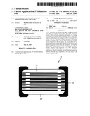 | 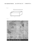 |
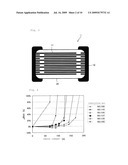 | 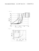 |
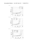 | 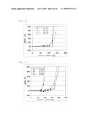 |
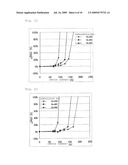 | 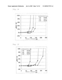 |
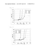 | 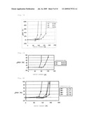 |
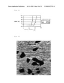 | 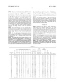 |
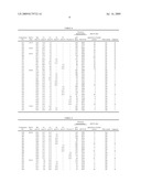 | 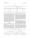 |
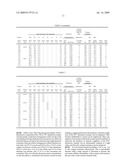 | 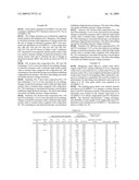 |
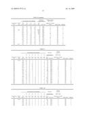 | 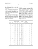 |
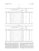 | 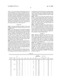 |
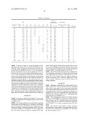 | 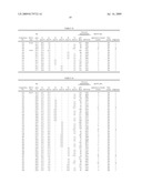 |
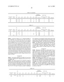 | 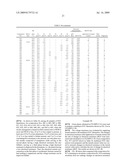 |
| Similar patent applications: | |
| Date | Title |
|---|---|
| 2012-06-21 | Ntc thermistor ceramic and ntc thermistor using the same |
| 2010-09-23 | Ptc device and process for manufaturing the same |
| 2011-03-24 | Ntc thin film thermal resistor and a method of producing it |
| 2012-07-26 | Thermistor and method for manufacturing the same |
| 2009-01-15 | Semiconductor device and method for manufacturing the same |
| New patent applications in this class: | |
| Date | Title |
|---|---|
| 2017-08-17 | Thermistor element |
| 2016-06-09 | Over-current protection device and protective circuit module containing the same |
| 2016-06-02 | Thermistor element |
| 2016-05-12 | Metal nitride material for thermistor, method for producing same, and film type thermistor sensor |
| 2016-05-05 | Metal nitride material for thermistor, method for producing same, and film type thermistor sensor |
| New patent applications from these inventors: | |
| Date | Title |
|---|---|
| 2011-01-20 | Ntc thermistor ceramic, method for producing ntc thermistor ceramic, and ntc thermistor |
| Top Inventors for class "Electrical resistors" | |
| Rank | Inventor's name |
|---|---|
| 1 | Clark L. Smith |
| 2 | Thomas L. Veik |
| 3 | Todd L. Wyatt |
| 4 | Werner Kahr |
| 5 | Torayuki Tsukada |