Patent application title: HEAT-DISSIPATING PLATE
Inventors:
Chun-Hung Lin (Taipei Hsien, TW)
Chang-Yin Chen (Taipei Hsien, TW)
Assignees:
COOLER MASTER CO., LTD.
IPC8 Class: AF28D1504FI
USPC Class:
16510426
Class name: Liquid fluent heat exchange material utilizing change of state utilizing capillary attraction
Publication date: 2011-06-09
Patent application number: 20110132578
Abstract:
A heat-dissipating plate has a casing and a supporting structure, where
the casing has surrounding walls to define a receiving compartment
therein confined by an inner wall. The inner wall is integrated with a
capillary structure. Disposed inside the receiving compartment, the
supporting structure includes a meshed partition and a plurality of
columns. The meshed partition has a plurality of holes and
joined-openings. The columns are fixed in the joined-openings and abut
against the inner surface of the walls. The associated manufacturing
process for the heat-dissipating plate is easily to accomplish.Claims:
1. A heat-dissipating plate, comprising a casing having surrounding
walls, wherein the walls are formed with capillary structure therein,
wherein the inner surface of the surrounding walls defines a receiving
compartment; and a supporting structure disposed in the receiving
compartment, wherein the supporting structure includes a meshed partition
and a plurality of columns, wherein the meshed partition has a plurality
of holes and joined-openings, and wherein the columns are fixed in the
joined-openings respectively, and wherein the columns abut against the
inner surface of the surrounding wall.
2. The heat-dissipating plate of claim 1, wherein the casing is flattened-shaped.
3. The heat-dissipating plate of claim 1, wherein the capillary structure is formed with copper powders.
4. The heat-dissipating plate of claim 1, wherein the meshed partition is made from a copper plate by punching.
5. The heat-dissipating plate of claim 1, wherein the meshed partition is extended with a plurality of fixing tabs from an inner edge of each joined-opening to hold the column.
6. The heat-dissipating plate of claim 5, wherein the fixing tabs and the meshed partition are formed with an included angle therebetween.
7. The heat-dissipating plate of claim 6, wherein the fixing tab has a hook-shaped body to hold the column.
8. The heat-dissipating plate of claim 1, wherein the fixing tab has a hook-shaped body to hold the column.
9. The heat-dissipating plate of claim 1, wherein each of the columns is formed with a capillary structure on a periphery thereof.
Description:
BACKGROUND OF THE INVENTION
[0001] 1. Field of the Invention
[0002] The instant disclosure relates to a heat-dissipating plate; and more particularly to a novel heat-dissipating device including a flattened casing tightly coupled to a supporting structure therein to achieve good thermal conductivity.
[0003] 2. Description of Related Art
[0004] A flat heat pipe is usually made of copper sheet and configured into closed hollow casing, in which the hollow portion is vacuum and filled with working fluids. A capillary structure is formed on an inner wall of the casing. However, during the vacuuming process, it is difficult to control the plane surface of the heat pipe. Thus, a supporting structure is usually inserted into the hollow casing to maintain the plane surface of the heat pipe. Some conventional supporting structure uses a copper net having a wavy-shaped supporting surface formed thereon to support the upper and the bottom walls of the hollow casing. Other conventional supporting structures employ a plurality of supporting columns fixed therein.
[0005] However, the copper net requires treatments to form a plurality of wavy supporting structure thereon to be used as a supporting structure. Thus, the required manufacturing process becomes more complex. On the other had, if supporting columns are used as the supporting structure, a soldering process is required to couple the columns to an upper and a lower wall of the heat pipe. The coupling process is also inconvenient and incurs high production costs.
[0006] Because of the technical limitations described above, the applicant strives via experience and academic research to develop the instant disclosure, which can effectively improve the limitations described above.
SUMMARY OF THE INVENTION
[0007] The object of the instant disclosure is to provide a heat-dissipating plate having a flattened casing which received a supporting structure therein.
[0008] Another object of the instant disclosure is to provide a supporting structure including a meshed partition which is combined with a plurality of columns.
[0009] A further object is to provide a capillary structure formed on an inner wall of the casing and the columns of the supporting structure.
[0010] To further appreciate the characteristics and technical contents of the instant disclosure, references are hereunder made to the detailed descriptions and appended drawings in connection with the instant disclosure. However, the appended drawings are merely shown for exemplary purposes, rather than being used to restrict the scope of the instant disclosure.
BRIEF DESCRIPTION OF THE DRAWINGS
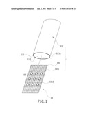
[0011] FIG. 1 is an exploded view of a heat-dissipating plate for the instant disclosure.
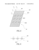
[0012] FIG. 2 is an isometric view of a supporting structure for he instant disclosure.
[0013] FIG. 3 is a side view of the supporting structure for the instant disclosure.
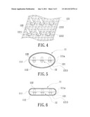
[0014] FIG. 4 is an enlarged view of a portion of the supporting structure,
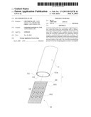
[0015] FIG. 5 is a cross-sectional view of the heat-dissipating plate prior to flatten the casing.
[0016] FIG. 6 is a cross-sectional view of a flattened heat-dissipating plate.
DETAILED DESCRIPTION OF PREFERRED EMBODIMENT
[0017] Please refer to FIG. 1, which shows a heat-dissipating plate according to the instant disclosure. The instant disclosure provides a heat-dissipating plate 1, which includes a casing 11 and a supporting structure 12.
[0018] The casing 11 has surrounding walls 111. The surrounding walls 111 are formed with a capillary structure 111a therein. The inner surface of the surrounding walls 111 defines a receiving compartment 112. A working fluid, such as water . . . etc., is filled in the receiving compartment 112. The capillary structure 111a formed on the walls 111 could be formed with copper powder.
[0019] The supporting structure 12 includes a meshed partition 121 and a plurality of columns 122. The meshed partition 121 could be made from a copper plate by punching. The meshed partition 121 has a plurality of holes 1211 and a plurality of joined-openings 1212. The joined-openings 1212 are slightly wider than the holes 1211. The meshed partition 121 has a plurality of fixing tabs 1213 extended from the inner edge of each joined-opening 1212. Each fixing tab 1213 has a hook-shaped body for retaining the column 122, but the retaining structure is not limited thereto. As shown in FIG. 4, a included angle is formed between the fixing tabs 1213 and the meshed partition 121. In other words, the fixing tabs 1213 are tilted and extended from a rim surrounded the joined-opening 1212 of the meshed partition 121. The columns 122 are plugged into the joined-openings 1212 respectively, where the fixing tabs 1213 secure the columns 122 onto the meshed partition 121. The top and bottom end surfaces of each column 122 abut on the surrounding wall 111.
[0020] Therefore, when the heat-dissipating plate 1 is placed on a heat-generating member (not shown), heat is conducted from the bottom to top portion of the surrounding wall 111 via each column 122. The heat-dissipating plate 1 provides excellent heat transfer, and the associated manufacturing process is easier accomplished.
[0021] Also, a capillary structure (not shown) can be formed on a periphery of the columns 122.
[0022] As shown in FIG. 5, a casing 11 could be a flatten oval-shaped tubing. The supporting structure 12 could be installed directly into the receiving compartment 112. Then, the casing 11 is flattened, and the receiving compartment 112 is vacuumed, filled with the working fluid, and sealed. As shown in FIG. 6, a flatten heat-dissipating plated is finished with the supporting structure inserted in the flatten casing.
[0023] The present disclosure at least has efficacy and the characteristics as followed.
[0024] 1. The instant disclosure provides a heat-dissipating plate, a new kind of flat heat pipe, which is inserted with the supporting structure to support the casing. It is easily to control the horizontal level of the surfaces of the heat-dissipating plate. Thus, the heat-dissipating plate can be mounted with a heat-producing element well.
[0025] 2. The supporting structure is a good supporter for the casing of heat-dissipating plate, and can strengthen the heat-dissipating plate.
[0026] 3. The manufacturing process of the heat-dissipating plate is easier. It can be easily started from a flattened elliptic tube as the casing, and insert the supporting structure into the casing. Then, to proceed to other processes for achieving the heat-dissipating plate, such as flattening, vacuuming, infusing working fluid, and sealing openings . . . etc.
[0027] The descriptions illustrated supra set forth simply the preferred embodiment of the instant disclosure; however, the characteristics of the instant disclosure are by no means restricted thereto. All changes, alternations, or modifications conveniently considered by those skilled in the art are deemed to be encompassed within the scope of the instant disclosure delineated by the following claims.
User Contributions:
Comment about this patent or add new information about this topic:
Images included with this patent application:
 |  |
 |  |
| Similar patent applications: | |
| Date | Title |
|---|---|
| 2010-09-30 | Heat-dissipating device including a plating metal layer |
| 2011-07-14 | Heat-dissipating plate |
| 2011-09-08 | Use of a graphite heat-dissipation device including a plating metal layer |
| 2009-07-09 | Heat dissipating apparatus extended laterally from heat pipe |
| 2009-08-06 | Heat-dissipating element and heat sink having the same |
| New patent applications in this class: | |
| Date | Title |
|---|---|
| 2019-05-16 | Method for preparing porous wick and product prepared by the same |
| 2019-05-16 | Semiconductor device assembly with vapor chamber |
| 2019-05-16 | Straight-through structure of heat dissipation unit |
| 2018-01-25 | Diphasic cooling loop with satellite evaporators |
| 2017-08-17 | Heat pipe |
| Top Inventors for class "Heat exchange" | |
| Rank | Inventor's name |
|---|---|
| 1 | Levi A. Campbell |
| 2 | Chun-Chi Chen |
| 3 | Tai-Her Yang |
| 4 | Robert E. Simons |
| 5 | Richard C. Chu |