Patent application title: TOTAL DISC REPLACEMENT DEVICE
Inventors:
Beat Lechmann (Grenchen, CH)
Roger Buerki (Chur, CH)
IPC8 Class: AA61F244FI
USPC Class:
623 1716
Class name: Bone spine bone including spinal disc spacer between adjacent spine bones
Publication date: 2011-03-03
Patent application number: 20110054618
Inventors list |
Agents list |
Assignees list |
List by place |
Classification tree browser |
Top 100 Inventors |
Top 100 Agents |
Top 100 Assignees |
Usenet FAQ Index |
Documents |
Other FAQs |
Patent application title: TOTAL DISC REPLACEMENT DEVICE
Inventors:
Beat Lechmann
Roger Buerki
Agents:
Assignees:
Origin: ,
IPC8 Class: AA61F244FI
USPC Class:
Publication date: 03/03/2011
Patent application number: 20110054618
Abstract:
The total disc replacement device (1) comprising a central axis (2), a
first and a second apposition plate (3; 5), a first and a second joint
component (4; 6) being mutually arranged in a ball joint like manner and
being located between said first and second apposition plates (3; 5) and
intermediate means (7) being disposed at least between the first
apposition plate (3) and the first joint component (4) in such manner
that, the first joint component (4) is not freely moveable transversely
to the central axis (2) with respect to the first apposition plate (3)
under load-free conditions, but a limited movement of the first joint
component (4) relative to the first apposition plate (3) transversal to
the central axis (2) is allowed under load.Claims:
1. A total disc replacement device (1) having a central axis (2) and
comprising:A) a first and a second apposition plate (3;5);B) a first and
a second joint component (4;6) being mutually arranged in a ball-joint
like manner and being located between said first and second apposition
plates (3;5); andC) intermediate means (7) being disposed at least
between the first apposition plate (3) and the first joint component (4)
in such manner that the first joint component (4) is not freely moveable
with respect to the first apposition plate (3) under load-free
conditions, but a limited movement of the first joint component (4)
relative to the first apposition plate (3) transversal to the central
axis (2) is allowed under load.
2. The device (1) according to claim 1, wherein the connection between the apposition plate and the joint component is clearance-free.
3. The device (1) according to claim 1 or 2, further comprising second intermediate means (9) being disposed between the second apposition plate (5) and the second joint component (6).
4. The device (1) according to one of the claims 1 to 3, wherein said intermediate means (7) are elastically deformable.
5. The device (1) according to one of the claims 1 to 3, wherein said intermediate means (7) are plastically deformable.
6. The device (1) according to one of the claims 1 to 5, wherein at least one of said intermediate means (7;9) is connected to the corresponding apposition plate (3;5) with a press-fit.
7. The device (1) according to one of the claims 1 to 6, wherein at least one of said intermediate means (7;9) is connected to the corresponding joint component (4;6) with a press-fit.
8. The device (1) according to one of the claims 1 to 7, wherein the press-fit of at least one of the intermediate means (7;9) within the adjacent apposition plate (3;5) or within the adjacent joint component (4;6) is obtainable by an elastic deformation of the intermediate means (7;9).
9. The device (1) according to one of the claims 1 to 8, wherein the press-fit of at least one of the intermediate means (7;9) within the adjacent apposition plate (3;5) or within the adjacent joint component (4;6) is obtainable by a plastic deformation of the intermediate means (7;9).
10. The device (1) according to one of the claims 1 to 9, wherein at least one the apposition plates (3;6) is connected to the corresponding joint component (4;6) by a plug-socket connection, such that at least a part of the apposition plate (3;5) and at least a part of the corresponding joint component (4;6) overlap one another coaxially to the central axis (2) and form an attachment zone (10;11).
11. The device (1) according to claim 10, wherein the intermediate means (7;9) is disposed between the apposition plate (3;5) and the corresponding joint component (4;6) only within the attachment zone (10;11), preferably within the whole attachment zone (10;11).
12. The device (1) according to one of the claims 1 to 11, wherein the Young's modulus of the material of the intermediate means (7;9) is lower than that of the adjacent apposition plate (3;5).
13. The device (1) according to one of the claims 1 to 12, wherein the Young's modulus of the material of the intermediate means (7;9) is lower than that of the adjacent joint component (4;6).
14. The device (1) according to one of the claims 1 to 13, wherein the intermediate means (7;9) consist of the material being selectable of the group of PEEK, PEKK or others members of the PEAK.
15. The device (1) according to one of the claims 1 to 14, wherein at least one of the apposition plates (3;5) consists of the material being selectable of the group of titanium and its alloys, CoCrMo, or stainless steel.
16. The device (1) according to one of the claims 1 to 15, wherein at least one of the joint components (4;6) consists of the material being selectable of the group of ceramics, preferably aluminium oxide, aluminium titanate, silicate ceramics and zirconium oxide, or of the group of CoCrMo or CoCrMoC alloys.
17. The device (1) according to one of the claims 1 to 16, wherein said apposition plates (3;5) and said adjacent joint components (4;6) consist of the same material.
18. The device (1) according to one of the claims 1 to 17, wherein said intermediate means (7;9) has an essentially cylindrical shape.
19. The device (1) according to claim 18, wherein the intermediate means (7;9) has an essentially circular-cylindrical shape.
20. The device (1) according to one of claims 1 to 3, 6 to 7 and 10 to 19, wherein at least one of the intermediate means (7;9) consists of a memory material.
21. The device (1) according to one of the claims 1 to 20, wherein said intermediate means (7;9) and the adjacent apposition plate (3;5) or the adjacent joint component (4;6) are connectable by means of a snap-fit.
22. The device (1) according to one of the claims 1 to 21, wherein said apposition plates (3;5) or joint components (4;6) are provided with a lip (73;93) and said intermediate means (7;9) are provided with a corresponding undercuts (11;111) such forming a snap-fit.
23. The device (1) according to one of the claims 1 to 21, wherein said apposition plates (3;5) or joint components (4;6) are provided with undercuts (11;111) and said intermediate means (7;9) are provided with a corresponding lip (73;93) such forming a snap-fit.
24. The device (1) according to one of claims 1 to 20, wherein the intermediate means (7;9) has a spring-shape being corrugated transversely to the central axis (2).
25. The device (1) according to one of the claims 10 to 24, wherein the attachment zone (10) has a height L of between 1,5 mm and 9 mm measured parallel to the central axis (2).
26. The device (1) according to one of the claims 1 to 25, wherein said intermediate means (7; 9) has a height H between 0,7 mm and 6,0 mm measured parallel to the central axis (2).
27. The device (1) according to one of the claims 1 to 26, wherein said intermediate means (7; 9) has a minimum volume of 60 mm.sup.3.
28. The device (1) according to one of the claims 1 to 27, wherein at least one of said intermediate means (7;9) and the corresponding apposition plate (3;5) consist of one piece.
29. The device (1) according to one of the claims 1 to 28, wherein at least one of said intermediate means (7;9) and the corresponding join component (4;6) consist of one piece.
30. The device (1) according to one of the claim 28 or 29, wherein the intermediate means are designed as plurality of projections (50).
31. The device (1) according to one of the claim 30, wherein the projections are T-shaped.
32. The device (1) according to one of the claim 30, wherein the projections are L-shaped.
Description:
[0001]The invention relates to a total disc replacement device comprising
a first and a second apposition plate, a first and a second joint
component and intermediate means disposed between the first apposition
plate and the first joint component.
[0002]Today implants or prostheses are inserted into the intervertebral space of two adjoining vertebral bodies after removal of a natural intervertebral disc or a nucleus pulposus of an intervertebral disc.
[0003]Usually hard material inlays for articulating components of total disc replacement implants are manufactured from super alloys or ceramic materials. These inlays are usually pressed or shrunk into titanium or super alloy bone contact plates, whereby the interface is subject to severe compression stresses.
[0004]Total disc replacement devices comprise components for the preservation of segmental motion. Some total disc replacement designs include one or more joints having spherical articulation, e.g., ball-and-socket joint. Materials used to construct the articulating elements can comprise combinations such as metal-on-polymer, metal-on-metal or ceramic-on-ceramic bearing as well as the combination of these materials. Generally, the material combinations aim for minimal wear debris volume and biocompatible wear particles.
[0005]An intervertebral implant is known from DE 2003 13 183 AESCULAP, wherein the articulating elements are arranged in an axially rotatable manner in the bone contact plates. The rotation of the articulating elements in the bone contact plates shows the disadvantage of abrasion and a higher clearance.
[0006]In embodiments where any rotation should be avoided, inlays are manufactured from hard materials (e.g., metal, metal alloys, and/or ceramic) that have various disadvantages when assembled or otherwise placed into the bone contact plates. Usually the inlay has overlapping dimensions or dimensions that allow the inly to be assembled into the component with a press-fit. However, press-fitting results in high compression forces that can stress the inlay and other components.
[0007]A metal inlay may be designed so that it deforms during a press-fit, resulting in a reduction of the clearance of the articulation. High compressive stress to ceramic elements is typically unproblematic if their design is structurally strong. However, total disc replacement devices are relatively small which usually prevents the use of a thick wall design. Since the ceramic material is brittle, and press- or shrink-fitting a ceramic portion of a total disc replacement device can damage the ceramic portion and results in small fragments with sharp edges that could damage. The major blood vessels located near the intervertebral discs. Therefore, stress shielding, particularly to the ceramic material, should be considered in the design.
[0008]On this point, the invention intends to provide remedial measures. The invention is based on the objective of providing a total disc replacement device, which allows a clearance-free connection between the apposition plate and the joint component corresponding thereto and which is provided with a stress shielding capacity in order to reduce the compression stress in the concerned interface.
[0009]In some embodiments, this invention provides a total disc replacement device that has a central axis and comprises a first and a second apposition plate, a first and a second joint component, and an intermediate means that is disposed at least between the first apposition plate and the first joint component. The first and second joint component can located between the first and second apposition plates. The first and second joint components can be mutually connected or arranged in a ball-joint like manner. The intermediate means can be disposed at least between the first apposition plate and the first joint component in such manner that the first joint component is not freely moveable transversely to the central axis with respect to the first apposition plate under load-free conditions, but a limited movement of the first joint component relative to the first apposition plate transversal to the central axis is allowed under load.
[0010]One advantage of the present invention is that it reduces or eliminates compressive stress on the various components of the total disc replacement device. For example, the intermediate means that can be disposed between an apposition plate and a joint component can reduce or eliminate the compressive force needed to assemble the device. Also, the intermediate means can reduce or eliminate the stresses born by the components when implanted into a patient.
[0011]Additional advantageous embodiments of the invention are characterized below.
[0012]In one embodiment of the invention at least one of the intermediate means is connected to the corresponding apposition plate or to the corresponding joint component with a press-fit. The advantages of such embodiment is to be seen in the facts that stresses due to the high compression forces between the adjacent components are reduced, clearance between the components is avoided and the respective members are firmly kept together. Due to the choice of the soft, elastic or thermoplastic properties of the intermediate means stress can be reduced since the softer component adapts its shape in order to establish a stress-balance.
[0013]In a further embodiment the intermediate means are elastically or plastically deformable so that a limited movement of the joint components relative to the corresponding apposition plates is allowed under load.
[0014]In another embodiment the press-fit of the intermediate means within the adjacent apposition plate or within the adjacent joint component is obtainable by an elastic deformation of the intermediate means. Due to such embodiments stress shielding is obtainable e.g. with insertion of a polymeric ring.
[0015]In a further embodiment the press-fit of the intermediate means within the adjacent apposition plate or within the adjacent joint component is obtainable by a plastic deformation of the intermediate means. Due to such embodiments stress shielding is obtainable e.g. with deformable means being integral with the adjacent apposition plate or the adjacent joint component.
[0016]In another embodiment the apposition plates are connected to the corresponding joint component by a plug-socket connection, such that at least a part of the apposition plate and at least a part of the corresponding joint component overlap one another coaxially to the central axis and form an attachment zone, whereby the intermediate means is disposed between the apposition plates and the corresponding joint component only within the attachment zone preferably within the whole attachment zone.
[0017]In a further embodiment the intermediate means has a height being smaller than a height of the attachment zone. The advantage of such embodiment can be seen in the fact that due to small height of the intermediate means a major deformation of said intermediate means is allowing.
[0018]In another embodiment the Young's modulus of the material of the intermediate means is lower than that of the adjacent apposition plate and/or lower than that of the adjacent joint component. Due to such embodiment the total disc replacement device may comprise components, particularly apposition plates and/or joint components may be made of a material having a high Young's modulus, e.g. use of titan or titan alloys being biocompatible or use of ceramics for the joint components.
[0019]In another embodiment the intermediate means consist of the material being selectable of the group of PEEK, PEKK or others members of the PEAK. The advantage of such embodiment can be seen in the fact that thermoplastic semi-crystalline polymers comprise elastic properties with a low grad of creep (alignment of macro-molecules under load). During and after the insertion of the stiff inlay, the intermediate means is able to adapt its shape and distribute the interface stress. Since this process is performed slowly, the risk of rapid load changes is reduced. PEEK, PEKK and other members of the PEAK family, even re-enforced with carbon fibres, PTFE, UHMWPE, all materials must be biocompatible.
[0020]In a further embodiment the apposition plates consist of the material being selectable of the group of titanium and its alloys, CoCrMo, or stainless steel and the joint components consist of the material being selectable of the group of ceramics, preferably aluminium oxide, aluminium titanate, silicate ceramics and zirconium oxide, or of the group of CoCrMo or CoCrMoC alloys.
[0021]In an additional embodiment the apposition plates and the adjacent joint components consist of the same material. If the design of the apposition plates would be sophisticated ("filigrane"), the use of a material with higher Young's modulus is indicated, i.e. CoCrMo alloy.
[0022]In a further embodiment said intermediate means has an essentially cylindrical, preferably circular-cylindrical shape. The advantages of such embodiments can be seen in the facts of uncomplicated manufacturing; homogeneous stress distribution; easier assembly of the snap fit. Furthermore, if the inlay is inserted in-situ (in the intervertebral space), the surgeon is independent from the axial position of the components.
[0023]In another embodiment the intermediate means consist of a memory material. After insertion of the intermediate means, they can be heated locally and find its final shape and position.
[0024]In a further embodiment said intermediate means and the adjacent apposition plate or the adjacent joint component are connectable by means of a snap-fit, whereby said apposition plates or joint components are provided with lip and said intermediate means are provided with a corresponding undercuts such forming a snap-fit. In another embodiment said apposition plates or joint components are provided with undercuts and said intermediate means are provided with a corresponding lip such forming a snap-fit. The advantage of the additionally form-locking connection of the intermediate means and the corresponding components can be seen in the fact of the prevention of the spontaneous dismantling and easy manufacturing of all components allowed thereby.
[0025]In a further embodiment the intermediate means has a spring-shape being corrugated transversely to the central axis. Such corrugated shape allows the use of a metallic material instead of a thermoplastic polymer.
[0026]In another embodiment the intermediate means and the corresponding apposition plate or the corresponding join component consist of one piece. The advantage of such embodiments can be seen in the fact of the tension distribution and the reduction of the high loading pressure.
[0027]In a further embodiment the intermediate means are designed as plurality of projections, whereby such projections are T-shaped or L-shaped.
[0028]The invention and additional configurations of the invention are explained in even more detail with reference to the partially schematic illustration of several embodiments.
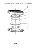
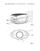
[0029]FIG. 1 illustrates an exploded view of an embodiment of the total disc replacement device according to the invention;
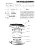
[0030]FIG. 2 illustrates a cross-section through the embodiment of FIG. 1;
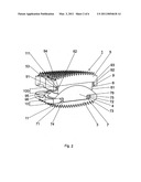
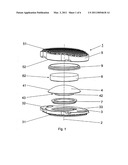
[0031]FIG. 3 illustrates an exploded view of another embodiment of the total disc replacement device according to the invention;
[0032]FIG. 4 illustrates a cross-section through the embodiment of FIG. 3;
[0033]FIG. 5 illustrates a top view on the first apposition member of the device of FIG. 3; and
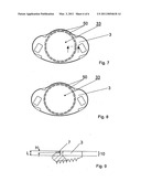
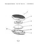
[0034]FIG. 6 illustrates an exploded view of a further embodiment of the total disc replacement device according to the invention;
[0035]FIG. 7 illustrates a top view on the first apposition member of the device of FIG. 6; and
[0036]FIG. 8 illustrates a top view on a further embodiment of the first apposition member of the total disc replacement device;
[0037]FIG. 9 illustrates a cross-section through the first apposition plate of the total disc replacement device;
[0038]The embodiment of the total disc replacement device 1 is shown in FIG. 1. Device 1 comprises a central axis 2, a first and a second apposition plate 3;5, a first and a second joint component 4;6, a first and second intermediate means 7;9.
[0039]When device 1 is implanted in a patient, central axis 2 lies essentially parallel to a longitudinal axis of the patient's vertebra. First and second apposition plate 3;5 are disposed transversely to central axis 2. First and second joint components 4;6 are located between said first and second apposition plates 3;5. Together, first and second joint components 4;6 form a ball-joint and are mutually connectable in a ball-joint like manner. First intermediate means 7 is disposed between first apposition plate 3 and first joint component 4. Second intermediate means 9 is disposed between second apposition plate 5 and second joint component 6.
[0040]First and second apposition plate 3;5 can be made of titanium or a titanium alloy. First and second joint component 4;6 can be made of a ceramic. The first and second intermediate means 7;9 can be made of an elastic materials, such as, for example a rubber or other type of polymer (e.g., PEEK).
[0041]Said first apposition plate 3 comprises a first contact surface 31 and a first intermediate surface 32. Accordingly, said second apposition plate 5 comprises a second contact surface 51 and a second intermediate surface 52. Both contact surfaces 31;51 as well as both intermediate surfaces 32;52 are arranged transversely to said central axis 2. Said first and second apposition plates are arranged relative to each other in a manner that the first and second intermediate surface 32;52 are turned to each other and the first and second contact surfaces 31;51, which is apt to abut the adjacent vertebral bodies, are turned away from each other. Additionally, said first and second apposition plates 3;5 each are provided with a three-dimensional structuring having a form of e.g., spikes and allowing an anchorage of said first and second apposition plates 3;5 in the adjacent vertebral bodies. Said first joint component 4 has a spherical convex sliding surface 41 being arranged concentrically to said central axis 2 and oppositely a first end portion 42 connected to said first apposition plate 3. Said second joint component 6 is provided with a spherical concave sliding surface 61 (FIG. 2) being slideably arranged, on said convex sliding surface 41 and opposite to said concave sliding surface 61 a second end portion 62 connected to said second apposition plate 5. In this manner, the mutual arrangement of concave sliding surface 61 and convex sliding surface 41 provide device 1 with ball-joint like movement.
[0042]Said first joint component 4 comprises circular cylindrical projection 43 being coaxial to the central axis 2 and being disposed at said first end portion 42 of said first joint component 4, whereby said first apposition plate 3 comprises the first recess 33 penetrating from said first intermediate surface 32 into said first apposition plate 3. In this manner, said circular cylindrical projection 43 may be inserted into the first recess 33 such said circular cylindrical projection 43 and said first recess 33 forming a first attachment zone 10 (FIG. 2). Furthermore, said second joint component 6 has a circular cylindrical second end portion 62 that may be inserted into the second recess 53 penetrating from said second intermediate surface 52 into said second apposition plate 5 such said second end portion 62 and said second recess 53 forming a second attachment zone 100. In this manner, each of said first and second apposition plates 3;5 is connected to the corresponding joint component 4;6 by a plug-socket connection, whereby the connection between the apposition plates 3;5 and the corresponding joint components (4;6) is clearance-free (i.e. no space between the apposition plates 3;5 and the corresponding joint components (4;6) is left to avoid free motion between them).
[0043]Said first intermediate means 7 is configured as a ring radially disposed between said circular cylindrical projection 43 and said first recess 33, whereby said circular cylindrical projection 43 is pressed into the central bore 71 of said first intermediate means 7. At the bottom surface 74 of said first intermediate means 7 the peripheral surface 72 of said first intermediate means 7 comprises a circular lip 73 forming a snap-fit with a circular undercut 11 at the bottom of said first recess 33. Adjacent to said first intermediate surface 32 of said first apposition plate 3 said first recess 33 has a diametrically enlarged section apt to press-fittingly receive a first flange 75 arranged at the top surface 76 of said first intermediate means 7.
[0044]Analogously, said second intermediate means 9 is configured as a ring radially disposed between said circular second end portion 62 and said second recess 63, whereby said circular second end portion 62 is pressed into the central bore 91 of said second intermediate means 9. At the top surface 94 of said second intermediate means 9 the peripheral surface 92 of said second intermediate means 9 comprises a circular lip 93 forming a snap-fit with a circular undercut 111 at the bottom of said second recess 53. Adjacent to said second intermediate surface 52 of said second apposition plate 5 said second recess 53 has an diametrically enlarged section apt to press-fittingly receive a second flange 95 arranged at the bottom surface 96 of said second intermediate means 9.
[0045]FIGS. 3-5 show a further embodiment of the total disc replacement device 1, whereby the intermediate means 7;9 are designed as a spring-like element. In contrast to the embodiment according to FIGS. 1 and 2 comprising a cylindrically shaped intermediate means 7;9 the embodiment according to FIG. 3 does not require a circular lip forming a positive fit, but allows a frictional fit or connection between the intermediate means 7;9 and the corresponding apposition plates 3;5. FIG. 5 shows the intermediate means 7 being frictionally locked in the first recess 33 of the first apposition plate 3. After the insertion of the cylindrical projections 43 of the first joint component 4 into the first recess 33 of the first apposition plate 3 respectively the second end portion 62 of the second joint component 6 into the second recess 53 of the second end apposition plate 5 the intermediate means 7;9 acting as a spring are plastically or elastically deformed and are clamped over the first and second attachment zones 10;100 with a press fit (FIG. 4).
[0046]FIG. 6 shows a further embodiment of the total disc replacement device 1, whereby the intermediate means and the corresponding apposition plates consist of one piece and the intermediate means are designed as a plurality of projections 50 formed in a T-shape configuration and being disposed on the periphery of the first and second recess 33;53. FIG. 7 shows a top view on the first apposition member 3 of the total disc replacement device according to FIG. 6 with the first recess 33 being provided with T-shaped projections 50 on the periphery of said recess 33.
[0047]FIG. 8 shows a top view of a further embodiment of the first apposition member of the total disc replacement device with the intermediate means and the first apposition plate 3 consisting of one piece, whereby the intermediate means are preformed as a plurality of L-shaped projections 50.
[0048]FIG. 9 shows a cross-section through the first apposition plate 3 of a further embodiment of the total disc replacement device 1, whereby the height H of the intermediate means 7 is smaller then the height L of the attachment zone 10.
User Contributions:
comments("1"); ?> comment_form("1"); ?>Inventors list |
Agents list |
Assignees list |
List by place |
Classification tree browser |
Top 100 Inventors |
Top 100 Agents |
Top 100 Assignees |
Usenet FAQ Index |
Documents |
Other FAQs |
User Contributions:
Comment about this patent or add new information about this topic:
Images included with this patent application:
 |  |
 |  |
 |  |
 |
| Similar patent applications: | |
| Date | Title |
|---|---|
| 2010-02-11 | Total disc replacement device |
| 2009-10-01 | Artificial disc replacement device |
| 2010-01-07 | Vertebral body and disc space replacement devices |
| 2010-11-11 | Total disc replacement system and related methods |
| 2011-08-25 | Total disc replacement with w-shaped spring elements |
| New patent applications in this class: | |
| Date | Title |
|---|---|
| 2022-05-05 | Dual wedge expandable implant with eyelets, system, and method of use |
| 2022-05-05 | Implant with deployable blades |
| 2019-05-16 | Interbody fusion cages |
| 2019-05-16 | Spinal fusion cage system with inserter |
| 2019-05-16 | Spinal implant system |
| New patent applications from these inventors: | |
| Date | Title |
|---|---|
| 2020-08-20 | Intervertebral implant |
| 2017-06-15 | Expandable intervertebral implant and associated method of manufacturing the same |
| 2017-02-16 | Expandable implant |
| 2016-11-17 | Expandable intervertebral implant and associated method of manufacturing the same |
| 2016-03-17 | Expandable bone implant |
| Top Inventors for class "Prosthesis (i.e., artificial body members), parts thereof, or aids and accessories therefor" | |
| Rank | Inventor's name |
|---|---|
| 1 | Anton G. Clifford |
| 2 | Yunbing Wang |
| 3 | Jan Weber |
| 4 | Chad Glerum |
| 5 | Robert Metzger |