Patent application title: GAS-TURBINE ENGINE WITH A TELESCOPIC AIR INLET IN THE ENGINE LINING
Inventors:
Predrag Todorovic (Berlin, DE)
Predrag Todorovic (Berlin, DE)
Assignees:
Rolls-Royce Deutschland Ltd & Co KG
IPC8 Class: AF02C7042FI
USPC Class:
415127
Class name: Rotary kinetic fluid motors or pumps including casing part selectively movable relative to fixed support circularly around fixed runner axis
Publication date: 2014-05-08
Patent application number: 20140127001
Abstract:
An aircraft gas-turbine engine has an engine cowling-nacelle which
surrounds a core engine in a tubular way, characterized in that at least
one inflow-side part of the engine cowling-nacelle is telescopically
movable against the flow direction.Claims:
1. Aircraft gas-turbine engine having an engine cowling-nacelle which
surrounds a core engine in a tubular way, characterized in that at least
one inflow-side part of the engine cowling is telescopically movable
against the flow direction.
2. Aircraft gas-turbine engine in accordance with claim 1, characterized in that the movable part extends at least up to behind a cowling of a fan in the flow direction.
3. Aircraft gas-turbine engine in accordance with claim 1, characterized in that the movable part includes an outer engine cowling and/or an inner engine cowling.
4. Aircraft gas-turbine engine in accordance with claim 3, characterized in that the movable part includes the outer engine cowling up to a thrust-reversing element and/or the inner engine cowling up to the cowling of the fan.
5. Aircraft gas-turbine engine in accordance with claim 1, characterized in that the movable part is designed tubular or partly tubular.
6. Aircraft gas-turbine engine in accordance with claim 1, characterized in that the movable part is mounted by means of telescopic rail guides.
7. Aircraft gas-turbine engine in accordance with claim 6, characterized in that the telescopic rail guides enable a substantially axial movement and/or at least a partly radial movement.
8. Aircraft gas-turbine engine in accordance with claim 1, characterized in that the inflow-side part can be moved by hand or by using an auxiliary drive unit.
Description:
[0001] This application is the National Phase of International Application
PCT/EP2012/002323 filed May 31, 2012 which designated the U.S.
[0002] This application claims priority to German Patent Application No. DE102011103163.8 filed Jun. 1, 2011, which application is incorporated by reference herein.
[0003] This invention relates to a gas-turbine engine having an engine cowling (nacelle) which surrounds the gas-turbine engine, in particular a core engine, and a bypass duct surrounding the latter.
[0004] Engine cowlings (nacelles) of aircraft gas-turbine engines include a plurality of assemblies and structural elements which are of complex design and require maintenance. They include, for example, the inflow area (air inlet), the fan casing, the thrust-reversing device and the outlet nozzle of the bypass duct. The inflow area includes here a de-icing device and acoustic damping means on its inner wall, sensors or similar elements. To perform maintenance work on the engine, it is known from the state of the art to remove individual partial areas of the engine cowling or to open them like cowls or doors. This requires a high and additional design effort, which entails a plurality of additional components. Furthermore, the maintenance effort is not inconsiderable, since a plurality of elements have to be removed or opened to provide access to the relevant assemblies. All in all, the result is also a high overall weight of the structure.
[0005] The object underlying the present invention is to provide a gas-turbine engine which, while being simply designed, easy and cost-effectively producible, affords good accessibility and good maintenance possibilities.
[0006] It is a particular object of the present invention to provide solution to the above problematics by a combination of the features of claim 1. Further advantageous embodiments of the present invention become apparent from the sub-claims.
[0007] In accordance with the invention, it is thus provided that at least one inflow-side part of the engine cowling is telescopically movable against the flow direction. This telescopic movement is substantially in the axial direction, making it possible to provide access to important structural elements of the engine by a simple movement of the tubular inflow area.
[0008] The movability provided in accordance with the invention of the engine cowling part on the inflow side can be achieved in a simple manner, where it is particularly favourable when the inflow-side area is mounted by means of a telescopic rail guide. The latter transmits the weight of the inflow-side part, in the opened state too, to the engine structure, so that the maintenance personnel do not have to open or carry away any heavy parts. Furthermore, movability proves particularly favourable with regard to the wind forces occurring, since in comparison with doors or cowls, no additional safety measures are required.
[0009] The inflow-side part of the engine cowling in accordance with the invention can be locked by means of simple locking mechanisms in the operable state. These locking mechanisms only need to be released to permit the movement. Since the movement is aligned against the flow direction of the engine, there is no risk of the inflow-side part moving automatically during flight.
[0010] In accordance with the invention, an integrated component is thus provided which can be telescopically moved and which creates the inflow area, the incoming-flow lip and a de-icing device while affording accessibility to components of the fan cowling. Hence a single module is created which is movable with very little effort.
[0011] In accordance with the invention, the movement can be made by hand, but it is also possible to provide an auxiliary drive unit (electric or pneumatic) for that purpose.
[0012] In accordance with the invention, the result is, in addition to simple operability, a reduction in the required parts and as a consequence of this a weight reduction.
[0013] Since the inflow-side part of the engine cowling is furthermore movable as an integral module, it is possible to design the outer surface flow-optimized. The disruptions to the flow occurring in the state of the art due to cowls, operating levers or the like can therefore be avoided.
[0014] Furthermore it is particularly favourable that seals can be provided on the telescopically movable part and/or the non-movable components in order to prevent flow losses in the closed state.
[0015] The present invention is described in the following in light of the accompanying drawing, showing an exemplary embodiment. In the drawing,
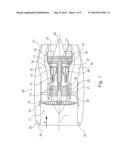
[0016] FIG. 1 shows a schematic representation of a gas-turbine engine in accordance with the present invention,
[0017] FIG. 2 shows a simplified partial sectional view of the telescopically movable inflow-side part of the engine cowling in the close state,
[0018] FIG. 3 shows a representation, by analogy with FIG. 2, in the opened state,
[0019] FIG. 4 shows a perspective partial sectional view of the inflow-side part of the engine cowling in accordance with the invention,
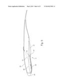
[0020] FIG. 5 shows a sectional view, by analogy with FIGS. 2 and 3, and
[0021] FIG. 6 shows an enlarged detail view of detail area A in accordance with FIG. 5.
[0022] The gas-turbine engine 10 in accordance with FIG. 1 is an example of a turbomachine where the invention can be used. The following however makes clear that the invention can also be used in other turbomachines. The engine 10 is of conventional design and includes in the flow direction, one behind the other, an air inlet 11, a fan 12 rotating inside a casing, an intermediate-pressure compressor 13, a high-pressure compressor 14, combustion chambers 15, a high-pressure turbine 16, an intermediate-pressure turbine 17 and a low-pressure turbine 18 as well as an exhaust nozzle 19, all of which being arranged about a center engine axis 1.
[0023] The intermediate-pressure compressor 13 and the high-pressure compressor 14 each include several stages, of which each has an arrangement extending in the circumferential direction of fixed and stationary guide vanes 20, generally referred to as stator vanes and projecting radially inwards from the engine casing 21 in an annular flow duct through the compressors 13, 14. The compressors furthermore have an arrangement of compressor rotor blades 22 which project radially outwards from a rotatable drum or disk 26 linked to hubs 27 of the high-pressure turbine 16 or the intermediate-pressure turbine 17, respectively.
[0024] The turbine sections 16, 17, 18 have similar stages, including an arrangement of fixed stator vanes 23 projecting radially inwards from the casing 21 into the annular flow duct through the turbines 16, 17, 18, and a subsequent arrangement of turbine blades 24 projecting outwards from a rotatable hub 27. The compressor drum or compressor disk 26 and the blades 22 arranged thereon, as well as the turbine rotor hub 27 and the turbine rotor blades 24 arranged thereon rotate about the engine axis 1 during operation.
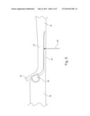
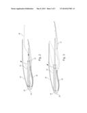
[0025] FIGS. 2 and 3 show a partial sectional view of the telescopically movable part 30 in accordance with the invention, both in the opened state (FIG. 3) and in the closed state (FIG. 2). The reference numeral 34 shows a thermal de-icing device of an incoming flow area 35 in a schematic representation. This device is designed according to the state of the art and includes for example an annular and tubular duct provided with outlet openings. The inflow-side part 30 thus forms that area of an engine cowling 29 which is at the front in the flow direction. The engine cowling 29 also includes a thrust-reversing element 31, shown only schematically in FIG. 1.
[0026] FIGS. 2 and 3 furthermore show an acoustic damping means 36 provided on the radially inner wall area of the inflow-side part 30. The reference numeral 37 indicates a bypass fan casing.
[0027] As can be seen from FIGS. 2 and 3, the inflow-side part 30 is movable by means of a telescopic rail guide 32 (see also FIG. 4). The telescopic rail guide 32 can also include means for supplying hot air 38 to the de-icing device 34. It is thus not necessary when opening the inflow-side part 30 (axial movement against the flow direction) to detach electrical, pneumatic or hydraulic connections.
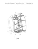
[0028] FIG. 4 is a perspective partial view showing structural elements inside the inflow-side part 30. In particular, frames 39 and annular carriers 40, which increase the stability of the overall structure, can be seen.
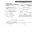
[0029] FIG. 5 shows in a schematic view, by analogy with FIG. 2, a supporting strut 41 which transmits forces, for example applied by a bird strike to the incoming flow area 35, into the overall structure.
[0030] FIG. 6 shows in an enlarged representation the transitional area between the component 36, which represents an acoustic damping means and is at the same time part of the inlet barrel, and the bypass fan casing 37. FIG. 6 shows that the bypass fan casing 37 has an extended area 43 in the forward direction with a radially outward-facing lip 42. Matching the latter, the inlet barrel 36 (acoustic damping means) is provided with an extension 44 which is located radially inside the extended area 43. The two parts 43 and 44 thus provide a telescopic arrangement formed from two annular areas 43 and 44. In between them is a seal 45 which can be designed as a lip seal or radial seal.
[0031] The extended area 43 and the extension 44 form at their contact surface a joint-like structure with "cardanic" action (gimbal joint). To do so, the radially outer surface of the extension 44 is designed with a spherical contour 46.
[0032] As can be discerned when viewing FIGS. 5 and 6 together, the lip 42 has a distance 47 from a longitudinal member 48 in the radially outward-facing direction. The longitudinal member 48 is a solid component of the supporting structure, while the acoustic damping means (inlet barrel) together with the bypass fan casing 37 is deformed in the event of a fan defect. If a fan blade (airfoil) is hit by a bird strike, for example, this leads to a sinusoidal deformation of the components 36 and 37. The distance 47 is provided to make this deformation possible. In these cases, the seal 45 furthermore provides a dependable sealing effect, and the joint-like bracing between the extended area 43 and the extension 44 (spherical contour 46) has the effect that forces can be transmitted in the Y and Z directions.
LIST OF REFERENCE NUMERALS
[0033] 1 Engine axis 10 Gas-turbine engine (core engine) 11 Air inlet 12 Fan rotating inside the casing 13 Intermediate-pressure compressor 14 High-pressure compressor 15 Combustion chambers 16 High-pressure turbine 17 Intermediate-pressure turbine 18 Low-pressure turbine 19 Exhaust nozzle 20 Guide vanes 21 Engine casing 22 Compressor rotor blades 23 Stator vanes 24 Turbine blades 26 Compressor drum or disk 27 Turbine rotor hub 28 Exhaust cone 29 Engine cowling (nacelle) 30 Inflow-side part of engine cowling 31 Thrust-reversing elements 32 Telescopic rail guide 33 Bypass duct 34 De-icing device 35 Incoming flow area 36 Acoustic damping means/inlet barrel 37 Bypass fan casing
38 Hot air
39 Frame
[0034] 40 Annular carrier 41 Supporting strut
42 Lip
[0035] 43 Extended area
44 Extension
45 Seal
[0036] 46 Spherical contour
47 Distance
[0037] 48 Longitudinal member
User Contributions:
Comment about this patent or add new information about this topic:
| People who visited this patent also read: | |
| Patent application number | Title |
|---|---|
| 20150118884 | ELECTRONIC DEVICE HAVING ELECTRONIC CARD CONNECTOR |
| 20150118883 | CONNECTOR |
| 20150118882 | CONNECTOR |
| 20150118881 | CONNECTOR |
| 20150118880 | POWER CONNECTOR WITH THERMAL CONDUCTIVITY |
Images included with this patent application:
 |  |
 |  |
 |  |
| Similar patent applications: | |
| Date | Title |
|---|---|
| 2014-09-04 | Turbine engine component with dual purpose rib |
| 2014-09-04 | Seal hook mount structure with overlapped coating |
| 2014-09-04 | Active clearance control system with zone controls |
| 2014-09-04 | Start-up method for a wind turbine and a control assembly |
| 2014-09-04 | Attachment apparatus for ceramic matrix composite materials |
| New patent applications in this class: | |
| Date | Title |
|---|---|
| 2018-01-25 | Multi-directional cooling fan |
| 2016-06-23 | Gas turbine engine with rotor blade tip clearance flow control |
| 2014-04-17 | Turbomachine |
| 2013-12-05 | Fan assembly |
| 2013-11-14 | Inner turbine shell axial movement |
| New patent applications from these inventors: | |
| Date | Title |
|---|---|
| 2021-06-17 | Jet engine air inlet arrangement and method for manufacture thereof |
| 2016-06-09 | Air intake arrangement |
| 2016-05-19 | Fully integrated air guide element |
| 2016-05-12 | Engine cowling of a gas turbine with thrust-reversing device and adjustable outlet nozzle |
| 2016-04-28 | Aircraft gas turbine thrust-reversing device having a guide rail |
| Top Inventors for class "Rotary kinetic fluid motors or pumps" | |
| Rank | Inventor's name |
|---|---|
| 1 | Gabriel L. Suciu |
| 2 | Frederick M. Schwarz |
| 3 | United Technologies Corporation |
| 4 | Brian D. Merry |
| 5 | Craig M. Beers |