Patent application title: Engine casing of an aircraft gas turbine having sound-absorbing elements in the fan inflow region
Inventors:
Predrag Todorovic (Berlin, DE)
Predrag Todorovic (Berlin, DE)
Rolls-Royce Deutschland Ltd & Co Kg
Thomas Kubisch (Koenigs Wusterhausen, DE)
Assignees:
Rolls-Royce Deutschland Ltd & Co KG
IPC8 Class: AF02C724FI
USPC Class:
415119
Class name: Rotary kinetic fluid motors or pumps with sound or vibratory wave absorbing or preventing means or arrangement
Publication date: 2014-03-06
Patent application number: 20140064928
Abstract:
The present invention relates to an engine casing of an aircraft gas
turbine having a radially inner honeycomb-structured layer arranged on
the engine casing in the flow direction upstream of a fan in the area of
an inflow-side air inlet, characterized in that sound-absorbing elements
are arranged radially outside at least one axial section of the
honeycomb-structured layer, said elements extending in the axial
direction and being arranged annularly next to one another in the
circumferential direction.Claims:
1. Engine casing of an aircraft gas turbine having a radially inner
honeycomb-structured layer arranged on the engine casing in the flow
direction upstream of a fan in the area of an inflow-side air inlet,
characterized in that sound-absorbing elements are arranged radially
outside at least one axial section of the honeycomb-structured layer,
said elements extending in the axial direction and being arranged
annularly next to one another in the circumferential direction.
2. Engine casing in accordance with claim 1, characterized in that each sound-absorbing element has at least one hollow chamber extending substantially in the axial direction and connected via recesses to the honeycomb-structured layer.
3. Engine casing in accordance with claim 1, characterized in that the sound-absorbing elements are arranged in a fan casing surrounding them radially on the outside.
4. Engine casing in accordance with claim 1, characterized in that the sound-absorbing elements are radially remote from the fan casing and/or the honeycomb-structured layer and at least partly form an intermediate chamber.
5. Engine casing in accordance with claim 1, characterized in that the sound-absorbing element is provided with at least one recess for connecting the intermediate chamber to the hollow chamber.
6. Engine casing in accordance with claim 1, characterized in that the sound-absorbing element in the circumferential direction has at least one sealing rib contacting the fan casing.
Description:
[0001] This application claims priority to German Patent Application
102012001571.2 filed Jan. 26, 2012, the entirety of which is incorporated
by reference herein.
[0002] This invention relates to an engine casing of an aircraft gas turbine and specifically to an aircraft gas turbine having a honeycomb-structured layer facing in the flow direction upstream of a fan radially inwards to an air inlet duct. The honeycomb-structured layer is designed with webs facing radially outwards in the form of a honeycomb, thus having a plurality of chambers. The latter are connected by recesses, for example in the form of a micro-perforation, to the air inflow region, in order to achieve in this way noise absorption. The honeycombs of the honeycomb-structured layer, which is made for example of metal or a composite material, form λ/4 absorbers.
[0003] In the designs known from the state of the art, an outer fan casing forms, together with the honeycomb structure, a structural unit. The design necessitates making the noise-absorbing structure, formed by the honeycomb-structured layer, in two or more parts in order to be in a position to fit the entire arrangement. The result is that the noise-absorbing arrangement is limited in terms of the installation space available and is hence particularly unsuitable for damping of low frequencies.
[0004] A broad aspect of the present invention is to provide an engine casing having sound absorption properties of the type specified at the beginning which, while being simply designed and easily and cost-effectively producible, enables optimum sound absorption, in particular of low frequency noise.
[0005] It is a particular object of the present invention to provide solution to the above problematics by a combination of the features of Claim 1. Further advantageous embodiments of the present invention become apparent from the sub-claims.
[0006] It is thus provided in accordance with the invention that additional sound-absorbing elements are arranged radially outside at least one axial section of the honeycomb-structured layer, said elements extending in the axial direction and being arranged annularly next to one another in the circumferential direction.
[0007] An additional sound-absorbing unit is thus formed in accordance with the invention in which the sound-absorbing elements are optimized due to their axial length for damping of low frequency noise. The sound-absorbing elements are arranged at an intermediate area between an inlet casing (part of the engine casing) and a fan casing. This permits the use of a longer axial area for sound absorption, and arrangement of the sound-absorbing elements such that they extend into an axial area of the fan casing. With this design, the honeycomb-structured absorbing elements known from the state of the art can be designed such that they are not subdivided in the axial direction and can hence provide effective sound absorption. A further advantage of the design in accordance with the invention is that it can be used without major design changes in existing engine casing structures (the term engine nacelle can also be used instead of engine casing).
[0008] It is thus possible to arrange the known honeycomb-structured layers up to the transition to the fan casing, and hence design them with a large axial length. The fan casing can accordingly be provided in accordance with the invention with a larger flange diameter to provide space for installing the sound-absorbing elements in accordance with the invention for damping lower frequencies.
[0009] Due to the embodiment in accordance with the invention and to the combination of the honeycomb-structured layer with the sound-absorbing elements in accordance with the invention, both λ/4 resonators and Helmholtz resonators can be designed. Since low-frequency noise is transmitted non-directionally, the arrangement in accordance with the invention and the embodiment of the sound-absorbing elements proves to be particularly effective.
[0010] In a favourable development of the invention, it is provided that each sound-absorbing element has at least one hollow chamber extending substantially in the axial direction and connected via recesses to the honeycomb-structured layer. The hollow chamber is thus used for damping low-frequency noise and permits, as mentioned above, a large volume and "big depth" required by λ/4 principles.
[0011] In a preferred embodiment of the invention, the sound-absorbing elements are arranged in a fan casing surrounding them radially on the outside, as already set forth above. With this arrangement and embodiment, an optimized overall structure is obtained which is simple and inexpensive to manufacture.
[0012] In order to improve in particular the damping of low-frequency vibrations, it is particularly advantageous when the sound-absorbing elements are radially remote from the fan casing and/ or the honeycomb-structured layer and at least partly form an intermediate chamber. It is particularly favourable here when the sound-absorbing element is provided with at least one recess for connecting the intermediate chamber to the hollow chamber. This ensures an effective sound wave introduction into the absorbing element.
[0013] It has proven particularly advantageous, in accordance with the invention, when several sound-absorbing elements are arranged in the circumferential direction in order to limit the individual intermediate chambers and hollow chambers. It is advantageous here when the sound-absorbing element has at least one sealing rib extending in the axial direction and designed in the radial direction such that it is contacting the fan casing.
[0014] In accordance with the invention, therefore, a three-dimensional absorbing structure is created by the sound-absorbing elements, which can be made of a metallic material or of composite material. A structural adaptation to the design situation of existing structures is made possible in a simple manner.
[0015] It is provided in accordance with the invention that the radially outer wall of the honeycomb-structured layer is provided with recesses, for example in the form of a micro-perforation, in order to pass low-frequency noise into the intermediate chamber or the hollow chamber. These sound waves are diverted in the sound-absorbing elements in accordance with the invention and routed in a labyrinth-type manner inside the sound-absorbing element, said sound waves (noise) being passed through the recess for connecting the intermediate chamber to the hollow chamber. The reflected sound waves (noise) then assume the same propagation path. This leads to a very efficient and effective sound absorption.
[0016] The sound-absorbing elements in accordance with the invention can furthermore be advantageously designed such that they can be used as force-transmitting structural elements.
[0017] Overall, the result is a very simply designed structure having a low weight and making optimum use of the available installation space. This results in a maximization of the possible sound absorption effect, which in turn leads both to better running characteristics of the fan and to a better load distribution.
[0018] The present invention is described in the following in light of the accompanying drawing, showing an exemplary embodiment. In the drawing,
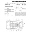
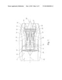
[0019] FIG. 1 shows a schematic representation of a gas-turbine engine in accordance with the present invention,
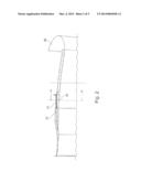
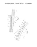
[0020] FIG. 2 schematically shows a simplified axial partial sectional view,
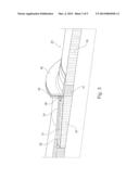
[0021] FIG. 3 shows an enlarged detail view according to FIG. 2,
[0022] FIG. 4 shows a sectional view along line A-A of FIG. 2,
[0023] FIG. 5 shows a sectional view along line B-B of FIG. 4, and
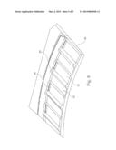
[0024] FIG. 6 shows a perspective partial representation of the sound-absorbing elements in accordance with the present invention.
[0025] The gas-turbine engine 10 in accordance with FIG. 1 is an example of a turbomachine where the invention can be used. The following however makes clear that the invention can also be used in other turbomachines. The engine 10 is of conventional design and includes in the flow direction, one behind the other, an air inlet 11, a fan 12 rotating inside a casing, an intermediate-pressure compressor 13, a high-pressure compressor 14, combustion chambers 15, a high-pressure turbine 16, an intermediate-pressure turbine 17 and a low-pressure turbine 18 as well as an exhaust nozzle 19, all of which being arranged about a central engine axis 1.
[0026] The intermediate-pressure compressor 13 and the high-pressure compressor 14 each include several stages, of which each has an arrangement extending in the circumferential direction of fixed and stationary guide vanes 20, generally referred to as stator vanes and projecting radially inwards from the engine casing 21 in an annular flow duct through the compressors 13, 14. The compressors furthermore have an arrangement of compressor rotor blades 22 which project radially outwards from a rotatable drum or disk 26 linked to hubs 27 of the high-pressure turbine 16 or the intermediate-pressure turbine 17, respectively.
[0027] The turbine sections 16, 17, 18 have similar stages, including an arrangement of fixed stator vanes 23 projecting radially inwards from the casing 21 into the annular flow duct through the turbines 16, 17, 18, and a subsequent arrangement of turbine blades 24 projecting outwards from a rotatable hub 27. The compressor drum or compressor disk 26 and the blades 22 arranged thereon, as well as the turbine rotor hub 27 and the turbine rotor blades 24 arranged thereon rotate about the engine axis 1 during operation. Reference numeral 28 shows an exhaust cone.
[0028] FIG. 2 shows a schematic partial representation of an engine casing 29 in accordance with the invention, where the flow comes from the right according to FIG. 2.
[0029] FIG. 3 shows an enlarged detail view according to FIG. 2. It can be seen here that a honeycomb-structured layer 30 is formed on the radially inner area of the engine casing 29 facing the air inlet 11. The honeycomb-structured layer has a micro-perforation or recesses 38 (see FIG. 5) through which sound waves can enter the honeycomb-structured layer 30.
[0030] FIG. 3 furthermore shows a fan casing 34 connected by means of a flange 39 to a flange 40 of the engine casing 29. A honeycomb structure 41 with high density or strength is provided in the area of the flange 40.
[0031] In the area of the fan casing 34, a sound-absorbing element 31 is shown radially outside the honeycomb-structured layer 30 in FIG. 3. The structure of the sound-absorbing element 31 is explained in detail in FIGS. 4 to 6.
[0032] As FIG. 6 shows, several sound-absorbing elements 31 are arranged next to one another in the circumferential direction. These elements are provided in the radial direction with different height ranges and each have at their rim areas a sealing rib 37 contacting the fan casing 34. As FIG. 5 shows, a radially outer intermediate chamber 35 and a radially inner hollow chamber 32 are formed in each case and are connected to one another by a recess 36. The radially outer side of the honeycomb-structured layer 30 has recesses 33, for example in the form of a micro-perforation. This allows sound waves to enter the honeycomb-structured layer 30 through the recesses/ micro-perforations 38 and to pass from there into the hollow chamber 32. From the latter, the sound waves pass through the recess 36 into the intermediate chamber 35. The labyrinthine structure already mentioned is thus obtained.
[0033] FIG. 6 shows that different areas are provided on the respective sound-absorbing element 31 in the circumferential direction. The area provided with the recess 36 is shown in FIG. 5 and forms the hollow chamber 32 and the intermediate chamber 35. Adjacently hereto, an area 42 (see also FIG. 4) is provided which directly contacts the honeycomb-structured layer 30. The result is an asymmetrical embodiment of the intermediate chamber 35 which leads to an optimization of the sound absorption.
LIST OF REFERENCE NUMERALS
[0034] 1 Engine axis
[0035] 10 Gas-turbine engine
[0036] 11 Air inlet
[0037] 12 Fan
[0038] 13 Intermediate-pressure compressor
[0039] 14 High-pressure compressor
[0040] 15 Combustion chambers
[0041] 16 High-pressure turbine
[0042] 17 Intermediate-pressure turbine
[0043] 18 Low-pressure turbine
[0044] 19 Exhaust nozzle
[0045] 20 Guide vanes
[0046] 21 Engine casing
[0047] 22 Compressor rotor blades
[0048] 23 Stator vanes
[0049] 24 Turbine blades
[0050] 26 Compressor drum or disk
[0051] 27 Turbine rotor hub
[0052] 28 Exhaust cone
[0053] 29 Engine casing/engine nacelle
[0054] 30 Honeycomb-structured layer
[0055] 31 Sound-absorbing element
[0056] 32 Hollow chamber
[0057] 33 Recess/micro-perforation
[0058] 34 Fan casing
[0059] 35 Intermediate chamber
[0060] 36 Recess
[0061] 37 Sealing rib
[0062] 38 Micro-perforation/recess
[0063] 39 Flange
[0064] 40 Flange
[0065] 41 Honeycomb structure
[0066] 42 Area
User Contributions:
Comment about this patent or add new information about this topic:
Images included with this patent application:
 |  |
 |  |
 |  |
| Similar patent applications: | |
| Date | Title |
|---|---|
| 2014-09-18 | Engine casing assembly |
| 2009-08-13 | Fan unit having a fan |
| 2014-08-07 | Vane arm having a claw |
| 2014-06-19 | Lightweight shrouded fan blade |
| 2011-01-27 | Peripheral tunnels propeller |
| New patent applications in this class: | |
| Date | Title |
|---|---|
| 2017-08-17 | Fan and air-conditioning apparatus using the same |
| 2016-12-29 | Turbine exhaust cylinder strut strip for shock induced oscillation control |
| 2016-07-14 | Suction device with sound mirror device |
| 2016-07-07 | Centrifugal fan, and fan equipped with sound-muffling box and using centrifugal fan |
| 2016-06-30 | Flexibly damped mounting assemblies for power gear box transmissions in geared aircraft engine architectures |
| New patent applications from these inventors: | |
| Date | Title |
|---|---|
| 2021-06-17 | Jet engine air inlet arrangement and method for manufacture thereof |
| 2016-06-09 | Air intake arrangement |
| 2016-05-19 | Fully integrated air guide element |
| 2016-05-12 | Engine cowling of a gas turbine with thrust-reversing device and adjustable outlet nozzle |
| 2016-04-28 | Aircraft gas turbine thrust-reversing device having a guide rail |
| Top Inventors for class "Rotary kinetic fluid motors or pumps" | |
| Rank | Inventor's name |
|---|---|
| 1 | Gabriel L. Suciu |
| 2 | Frederick M. Schwarz |
| 3 | United Technologies Corporation |
| 4 | Brian D. Merry |
| 5 | Craig M. Beers |