Patent application title: APPARATUS FOR SECURE DEVICE TO EDGE OF PLATE
Inventors:
Taiming Chen
IPC8 Class: AF28F700FI
USPC Class:
165185
Class name: Heat exchange heat transmitter
Publication date: 2013-08-08
Patent application number: 20130199768
Abstract:
Apparatuses to secure surface mount heat emitting device with back heat
spreader to edge of a heat dissipate plate in order to conduct heat from
said heat emitting device to heat dissipate plate directly. Each
apparatus comprising of adapter PCB with device mounting pads on surface
and opening at location of back heat spreader to expose it for contact
access; heat dissipate plate has contact stub to make contact with said
back heat spreader and bounding means to bound together said heat
dissipate plate and PCB.Claims:
1) An apparatus to secure heat emitting device with back heat spreader to
edge of a heat dissipate plate, said apparatus comprising of: a) An
adapter PCB for mounting said heating emitting device and securing to
edge of heat dissipate plate, said adapter PCB includes: i) mounting pads
for solder said heat emitting device on to PCB surface, ii) Hole under
said heat emitting device for exposing said device's heat spreader to
said heat dissipate plate, iii) shape of said PCB is narrower at first
dimension and wider at second dimension for locking said PCB when
rotated, b) Seating means on edge of said heat dissipate plate to accept
said adapter PCB, said seating means include: i) a first cut out with
opening matches the width of said first dimension of adapter PCB and
depth greater than thickness of said adapter PCB, ii) two right angled
slots on symmetric location of both sides of first cut out with width
matches to thickness of said adapter PCB for accepting said PCB when
inserted and rotated, iii) contact stub at edge of said heat dissipate
plate with width that can fit into said hole of adapter PCB and has
length to touch heat spreader of said heat emitting device through said
adapter PCB when PCB is inserted and secured with said seating means.
2) The apparatus of claim 1, wherein proxy material is applied between said back heat spreader of heat emitting device and said contact stub to help dissipate heat.
3) An apparatus to secure heat emitting device with back heat spreader to edge of a heat dissipate plate, said apparatus comprising of: a) At least one heat emitting device that has a plurality of mounting points and back heat spreader, said mounting points and back heat spreader is aligned to be mount on a plane surface; b) A PCB with two sides for mounting at least one said heat emitting device and securing said devices to edge of said heat dissipate plate, said PCB includes: i) a plurality of mounting pads on first side of PCB surface for soldering said mounting points of heat emitting devices on to said first side of PCB, ii) at least one through opening between first and the opposite side, or second side, of said PCB to allow contact surface of said heat dissipate plate to pass through said PCB from second side to come out of first side of PCB; c) At least one heat dissipate plate to dissipate heat from said heat emitting devices, said heat dissipate plate includes: i) Plate has main body and surface area on both sides of plate to dissipate heat away from said heat emitting device, ii) A least one contact tab connect to but stick out of said plate main body for the length of equal or greater than the thickness of said PCB for fitting through said PCB through opening, iii) at least one contact surface on edge side of said contact tab to made proper contact with back heat spreader of said heat emitting device alongside the first side of said PCB; d) Bounding means to secure said PCB to said heat dissipate plate.
4) The apparatus of claim 3, wherein said through opening is slot with width equal to thickness of said heat dissipate plate.
5) The apparatus of claim 3, wherein said bounding means are a plurality of stabilizer stubs bent off both sides of said heat dissipate plate to support and restrict said PCB from moving or rolling at either directions.
6) The apparatus of claim 3, wherein said bounding mean are a plurality of retaining stubs that went through the said through opening of PCB and got bent down to clamp on first surface of said PCB to hold PCB in position.
7) The apparatus of claim 3, wherein said bounding mean is at least one solder pad on said PCB to provide solder bounding together with said heat dissipate plate.
8) The apparatus of claim 3, wherein said bounding mean is very tight fitting through opening slot to clamp on said heat dissipate plate, the fraction force between said PCB and said plate provide great force to keep them from moving apart.
9) The apparatus of claim 3, wherein said PCB has heat conducting surface plating from said heat emitting device's back heat spreader to a close proximity of said contact surface to help dissipate heat.
10) The apparatus of claim 3, wherein proxy conducting material, such as heat conducting paste, is applied between said back heat spreader of heat emitting device and said contact stub to help dissipate heat.
11) The apparatus of claim 3, wherein proxy bounding material, such as glue or solder, is applied between said heat dissipate plate and said PCB to provide bounding between these two.
12) The apparatus of claim 3, wherein said adapter PCB has a plurality of said heat emitting devices mounted along the edge of said heat dissipate plate, each said device has at least one said contact surface to make contact with.
13) The apparatus of claim 3, wherein said adapter PCB has circuit printed on and use said heat dissipate plate as common grounding.
Description:
FIELD OF THE INVENTION
[0001] The present invention relates, in general, to a heat emitting electronic device mounted on Printed Circuit Board (PCB) with need to dissipate heat.
BACKGROUND OF THE INVENTION
[0002] The present invention relates, in general, to apparatuses for securing device to edge of plate, more particular, this invention relates to mounting heat emitting device, such as high power LED, to heat dissipate plate. Many devices can emit quite a lot of heat and need to be accelerated dissipated. Some devices pass along heat through their mounting leads to Print Circuit Board (PCB). Some devices have top or back heat spreader. The ones with top heat spreader can wear a heat sink on top to dissipate heat. Devices with back heat spreader, such as high power LED which has light emitting portion on top and can't have top heat spreader, has to press against PCB to dissipate heat. In some cases, heat sinks are added to against the other side of PCB to help dissipate heat. That's not as efficient as heat has to travel through PCB before reach to heat sink.
DESCRIPTION OF PRIOR ART
[0003] U.S. Pat. No. 5,785,418 to Peter A. Hochstein describes a LED array attach PCB and then to heat sink block to fast dissipate heat.
[0004] U.S. Pat. No. 7,227,750 to Bishou Chen, Sheng Li describes a LED module has pins to conduct heat to back of PCB.
[0005] U.S. Pat. No. 7,806,574 to Peter Van Laanen and Jeff Bisberg describes a LED base lighting system which dissipates heat through PCB and structure member.
[0006] Application Ser. No. 12/928,644 from Taiming chen (same Inventor) describes a LED LAMP comprising of modules with LEDs mounted on edge of plates.
BRIEF SUMMARY OF THE INVENTION
[0007] Apparatuses to secure heat emitting device with back heat spreader to edge of a heat dissipate plate. Said apparatuses comprising of adapter PCB with device mounting pads and open hole at location of back heat spreader to expose it for access, seating means has a plurality of stubs at edge of said heat dissipate plate to accept and secure said adapter PCB, at least one contact stub at edge of heat dissipate plate to make contact with back heat spreader of each said heat emitting device.
BRIEF DESCRIPTION OF THE DRAWINGS
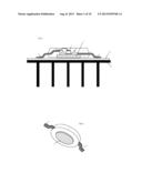
[0008] FIG. 1 is a section view of traditional LED, PCB and heat sink.
[0009] FIG. 2 is a perspective view of a surface mount LED
[0010] FIG. 3 is a top view of adapter PCB
[0011] FIG. 4 is a perspective view of LED mounted on adapter PCB
[0012] FIG. 5 is a perspective view of apparatus, before PCB inserted.
[0013] FIG. 6 is a perspective view of apparatus, with PCB inserted
[0014] FIG. 7 is a perspective view of apparatus, with PCB inserted.
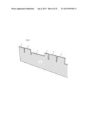
[0015] FIG. 8 is a perspective view of a pre-bent plate.
[0016] FIG. 9 is a perspective view of apparatus before assembly.
[0017] FIG. 10 is a perspective view of apparatus with LED device.
[0018] FIG. 11 is a perspective view of apparatus.
[0019] FIG. 12 is a perspective view of apparatus assembled.
[0020] FIG. 13 is a perspective view of apparatus.
DETAILED DESCRIPTION OF THE PREFERRED EMBODIMENT
[0021] Prior to proceeding to the more detailed description of the present invention, it should be noted that, for the sake of clarity and understanding, identical components which have identical functions have been identified with identical reference numerals throughout the several views illustrated in the drawing figures.
[0022] FIG. 1 shows a surface mount LED 1, mounted on top of a PCB 18. The diode silicon 1 is where light is emitted, and the diode is sitting on a substrate which connects to back heat spreader 5, surrounded by case 2. When mounted on PCB, LED's back heat spreader 5 press against PCB 18 to dissipate heat. Another heat sink 30 is attached to the other side of PCB 18 to further help heat dissipation.
[0023] FIG. 2 is a perspective view of LED 1.
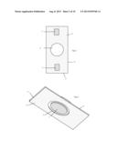
[0024] FIG. 3 shows top view of adapter PCB 10 of presenting apparatus. It has solder pads 11 and open hole 12. Open hole 12 should reveal back heat spreader 5 when LED is mounted. The shape of PCB 10 is rectangular with narrower side 15 and wider side 16.
[0025] FIG. 4 shows device's back heat spreader 5 is revealed through open hole 12, LED 1 is mounted on adapter PCB 10.
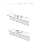
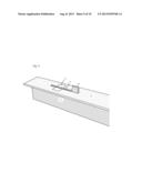
[0026] FIG. 5 shows adapter PCB 10 is at close range of seating means opening 21. The width of narrower side 15 should be match but less than the opening width of cut opening 21. There are two right angle slots 22 with width match to PCB 10 to accept said PCB when inserted and rotated. Contact stub 23 should be able to fit through the open hole 12 of adapter PCB 10 when rotated.
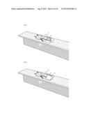
[0027] FIG. 6 shows adapter PCB 10 is inserted and rotated, so part of PCB body slide into the right angled slots 22. This holds PCB 10 from dropping out and form a seating means.
[0028] FIG. 7 shows another view of apparatus as FIG. 6. The contact stub 23 makes contact to back heat spreader 5 to conduct heat from LED to wider area of plate 20.
[0029] FIG. 8 shows a perspective view of heat dissipating metal plate 40 with cut out to form stubs 41, 42, 43, and 44.
[0030] FIG. 9 shows a perspective view of an adapter PCB 50 with through opening 51 and surface plating 52. Through opening 51 is connected first and second through opening in continuous; surface plating 52 is between the position of said device's back heat spreader to through opening 51. FIG. 9 also shows the same heat dissipating metal plate 40 as FIG. 8, stub 41 and 42 are bent to right angle to work as stabilizer stubs, stub 41 is bent to one direction vertical to plate 40, and stub 42 is bent to the other direction vertical to plate 40.
[0031] FIG. 10 shows a perspective view of an adapter PCB 50 with a surface mount LED device 1 mounted.
[0032] FIG. 11 shows a perspective view of apparatus with heat dissipating plate 40 being inserted into the through opening 51 of adapter PCB 50. Contact stub 43 fills the opening 51 to the surface level of PCB and to against the back of surface mount device 1.
[0033] FIG. 12 shows a perspective view of same apparatus as FIG. 11, with retaining stub 44 bent to hold down adapter PCB 50 in position, retaining stub also makes contact with surface plating 52.
[0034] FIG. 13 shows a perspective view of same apparatus as FIG. 11, without the surface mount device. Surface plating 52 is at position of device's back heat spreader, area where retaining stub will bend over and in close proximity or in contact with contact stub 43.
User Contributions:
Comment about this patent or add new information about this topic:
Images included with this patent application:
 |  |
 |  |
 |  |
 |  |
 |  |
 |
| Similar patent applications: | |
| Date | Title |
|---|---|
| 2014-05-29 | Bracket for supporting electronic device |
| 2014-06-05 | Connecting reinforcement for between the plates of a heat exchanger |
| 2014-06-05 | Heating/cooling system for indwelling heat exchange catheter |
| 2014-06-05 | Cooling device, and electronic apparatus with the cooling device |
| 2014-06-05 | Termperature control logic for refrigeration system |
| Top Inventors for class "Heat exchange" | |
| Rank | Inventor's name |
|---|---|
| 1 | Levi A. Campbell |
| 2 | Chun-Chi Chen |
| 3 | Tai-Her Yang |
| 4 | Robert E. Simons |
| 5 | Richard C. Chu |