Patent application title: HOUSEHOLD IMPLEMENT HOLDER
Inventors:
Kelly A. Duffy (Minden, NV, US)
IPC8 Class: AA47G2900FI
USPC Class:
211 601
Class name: Supports: racks special article article includes elongated portion
Publication date: 2013-06-06
Patent application number: 20130140255
Abstract:
A household implement holder can be used to hang household implements
such as fly swatters. A unit has a vertical shaft connected to a base and
concealment shield. The implement suspended from the vertical shaft. The
vertical shaft may be attached to a vertical surface such as a wall or
the unit may be free-standing. The bottom of the implement is hidden in a
volume behind the concealment shield when it is suspended from the
vertical shaft. The unit may be constructed of different materials, such
as wood, plastic, metal, any similar materials, or any combination
thereof.Claims:
1. A household implement holder for hanging and concealing a household
implement having a handle comprising: a base; a vertical shaft attached
to the base; a concealment shield permanently attached to the base, the
concealment shield having at least a front portion; and a suspending
feature configured to engage with the handle of the household implement
disposed on the vertical shaft at a height selected to position a bottom
portion of the household implement behind the concealment shield when the
handle of the household implement is engaged with the suspending feature.
2. The household implement holder of claim 1 further including fastening means on the vertical shaft for removably attaching the household implement holder to a vertical surface.
3. The household implement holder of claim 2 wherein the fastening means comprises at least one circular void communicating with an upper slot having side shoulders.
4. The household implement holder of claim 1 wherein the base has a flat bottom to allow the concealment shield to be free-standing.
5. The household implement holder of claim 1 formed from at least one material from a set comprising: wood, plastic, and metal.
6. The household implement holder of claim 1 further comprising a top portion coupled to a top of the vertical shaft.
7. The household implement holder of claim 1 wherein the suspending feature comprises one of a peg, a hook, and a void shaped to engage a feature on the handle of the household implement.
8. The household implement holder of claim 1 wherein: the household implement holder is formed from wood; and the concealment shield comprises a front section, a first side section, and a second side section mechanically coupled to the base and spaced apart from the vertical shaft to define a volume sized to accommodate the bottom portion of the household implement.
9. The household implement holder of claim 1 wherein: the household implement holder is constructed primarily from a plastic; and the concealment shield is formed as a single section mechanically coupled to the base and spaced apart from the vertical shaft to define a volume sized to accommodate the bottom portion of the household implement.
Description:
BACKGROUND OF THE INVENTION
[0001] 1. Field of the Invention
[0002] The present invention relates to a household implement holder and, more specifically, to a household implement holder having a concealment shield attached to a base to hold a household implement having a handle while concealing a bottom portion thereof.
[0003] 2. The Prior Art
[0004] One problem that arises with the use of certain household implements such as fly swatters is that they are unsightly and unsanitary. Yet, there is no good place to store them when not in use. In some cases, the household implements are left out, where they are unsightly and can create a disease hazard due to their unsanitary nature. In other cases, they are stored somewhere in the house, and they are inconvenient when most needed. It would be advantageous to provide a unit in which the household implement could be safely and cleanly stored when not in use, but where the household implement is readily available for use.
BRIEF SUMMARY OF THE INVENTION
[0005] The present invention relates to a useful, novel, and unobvious invention for a household implement holder in the home furnishing field.
[0006] A household implement holder can be used to store household implements having handles such as fly swatters. A household implement holder has a vertical shaft connected to a base to which a concealment shield is attached. The implement may be hung by its handle from a hook or peg on the implement holder. The vertical shaft may be attached to a vertical surface such as a wall or the unit may be supported by its base and be free-standing. The concealment shield is coupled to the base. The bottom of the household implement rests in the concealment volume behind the concealment shield when it is hung from the hook or peg. The household implement holder may be constructed of different materials, such as wood, plastic, metal, any similar materials, or any combination thereof.
BRIEF DESCRIPTION OF THE DRAWINGS
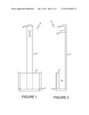
[0007] FIG. 1 is a front view of the household implement holder, in accordance with one embodiment of the present invention.
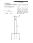
[0008] FIG. 2 is a side view of the household implement holder shown in FIG. 1.
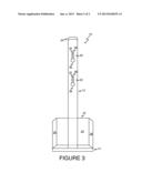
[0009] FIG. 3 is a rear view of the household implement holder shown in FIGS. 1 and 2.
DETAILED DESCRIPTION
[0010] Persons of ordinary skill in the art will realize that the following description of the present invention is illustrative only and not in any way limiting. Other embodiments of the invention will readily suggest themselves to such skilled persons.
[0011] The present invention is directed to household implement holder that can be used to hang up household implements with handles, such as fly swatters, concealing the lower portion of the implement when hung in the household implement holder. A household implement holder will typically have a vertical shaft connected at its lower end to a base. A concealment shield is coupled to the base. The implement being partially concealed may be hung by its handle from a hook or peg attached to the vertical shaft. The vertical shaft may be attached to a vertical surface such as a wall or the unit may be free-standing. The bottom of the household implement is hidden behind the concealment shield when it is hung on the hook or peg.
[0012] Referring now to FIGS. 1 and 2, front and side views are shown of an illustrative household implement holder 10, in accordance with one embodiment of the present invention. The household implement holder 10 has a vertical shaft 12 supported by base 14. A concealment shield 16 that conceals the bottom portion of a household implement is mechanically coupled to or integral with the base 14. A peg or hook 18 is disposed near the top of the vertical shaft 12 and is used to hang or suspend the household implement such that its bottom portion is behind the concealment shield 16 within a concealment volume denoted at reference numeral 22.
[0013] Referring now to FIG. 3, a rear view shows the household implement holder 10 of FIGS. 1 and 2. The concealment shield 16 in the illustrative embodiment of FIG. 3 is shown comprising front shield section 24, first side shield section 26 on one side of the front shield section 20, and second side shield section 28 on the opposite side of the front shield section 24. Sections 24, 26 and 28 are shown mounted to base 14 using any conventional technique. Molds to make the implement holder may include physical features that enable separate pieces to be fitted together without tools or fasteners. Persons of ordinary skill in the art will appreciate that, while this embodiment is shown having separate vertical shaft 12, front shield section 24, and side shield sections 26 and 28, one or more of these sections or elements may be combined. For example, in other embodiments, the front shield section 24 and side shield sections 26 and 28 may be integrally formed as a single section of molded plastic and may present a curved rather than angled surface.
[0014] Also shown are first and second mounting slots 30 and 32 on the back of the vertical shaft 12. In this embodiment, the first mounting slot 30 and second mounting slot 32 are each formed as a vertical slot 34 with a larger circular opening 36 at the bottom. The vertical slot has opposing side shoulders shown at dashed lines 38 in first mounting slot 30 and second mounting slot 32. Thus, the household implement holder 10 can be hung or attached to a wall by use of fasteners such as nails, tacks, screws, or bolts having heads, wherein the head of the fastener is inserted through the circular holes, and then slid down, with the fastener heads sliding up the vertical slot and being captured by the side shoulders. In other embodiments of the invention, one or more through holes may be provided instead of slots, or the unit may be affixed to a vertical surface using an adhesive. In yet other embodiments, the vertical shaft may be entirely omitted and the household implement may be suspended from a separate hook, peg, or the like.
[0015] Persons of ordinary skill in the art will appreciate that this embodiment is merely illustrative, and other methods of attaching the household implement holder to a wall or other surface, such as mounting holes passing completely through the vertical shaft from front to back are also within the scope of the present invention. Furthermore, some embodiments of the household implement holder 10 may also be free-standing on a horizontal surface, wherein the base 14 is flat, enabling it to be free standing without requiring that it be attached by vertical shaft 12 to a vertical surface.
[0016] A particular embodiment disclosed in FIGS. 1 through 3 may be constructed from wood. In this embodiment, pieces of wood are utilized to construct a household implement holder 10: the vertical shaft 12, bottom section 14, front shield section 24, first side shield section 26, second side shield section 28, top section 20 and peg or hook 18. The construction utilizing these sections can be readily determined from the drawing figures. This embodiment is exemplary, and other materials and construction techniques are also within the scope of the present invention. As one non-limiting example, a part or all of the household implement holder 10 can be made using many types of plastic materials as well as from many other common manufacturing materials by techniques such as molding as is known in the art.
[0017] In the embodiment shown in these FIGS. 1 through 3, the concealment shield 16 has a front section 24 and side sections 26 and 28. Persons of ordinary skill in the art will appreciate that the illustrated embodiment is illustrative only and that other configurations are also within the scope of the present invention.
[0018] Furthermore, the front surface of the front and sides of the unit, and, in particular, the concealment shield may be decorated. This can be done before sale, or later by a person wishing to customize the household implement holder. Decorating household implement holders can be accomplished as an art project. After market decorating of the household implement holders may be made easier if the household implement holders are constructed from a white material, such as plastic. Nevertheless, the household implement holders may be manufactured in other colors as well.
[0019] The disclosed embodiment was designed to provide concealment for a household implement such as a flyswatter. However, household implement holders for other household implements, such as toilet brushes and plungers, are also within the scope of the present invention. In the case of a flyswatter, the corresponding household implement holder will typically contain a relatively narrow concealment volume for the flyswatter, given the thin, flat nature of its bottom paddle. Other household implements with handles, such as toilet brushes and plungers, are wider and thicker at their base, and, thus, require a wider concealment volume.
[0020] Persons of ordinary skill in the art will recognize that modifications and variations can be made without departing from the spirit of the invention. Therefore, it is intended that this invention encompass all such variations and modifications as fall within the scope of the appended claims.
User Contributions:
Comment about this patent or add new information about this topic:
Images included with this patent application:
 |  |
 |
| Similar patent applications: | |
| Date | Title |
|---|---|
| 2015-10-15 | Theft resistant upstanding mount for temporary positioning of costly equipment at unattended outdoor locations |
| 2015-10-29 | Support apparatus for multiple display devices |
| New patent applications in this class: | |
| Date | Title |
|---|---|
| 2016-03-10 | Support for storing and displaying elongate articles |
| 2016-02-11 | Pipe racks |
| 2015-10-29 | Lock rack for hydro, isolation or test blinds |
| 2015-05-07 | Rust-preventing base support for metal containers |
| 2015-03-12 | Adjustment device for cable management arm |
| Top Inventors for class "Supports: racks" | |
| Rank | Inventor's name |
|---|---|
| 1 | Stephen N. Hardy |
| 2 | Wen-Tsan Wang |
| 3 | Gregory M. Bird |
| 4 | Shane Obitts |
| 5 | Kaveh Didehvar |