Patent application title: HEAT SINK AND ASSEMBLY METHOD THEREOF
Inventors:
Jian Liu (Shenzhen City, CN)
Jing Zhang (Shenzhen City, CN)
Assignees:
FOXCONN TECHNOLOGY CO., LTD.
FU ZHUN PRECISION INDUSTRY (SHEN ZHEN) CO., LTD.
IPC8 Class: AF28F700FI
USPC Class:
165185
Class name: Heat exchange heat transmitter
Publication date: 2012-06-28
Patent application number: 20120160467
Abstract:
An exemplary heat sink includes a base plate and a fin unit including
fins stacked together and arranged on the base plate. The base plate
includes two fixing portions extending upward from a top surface thereof.
Each of the fixing portions defines a groove therein. Each of the fins
includes a main body and two fixing strips extending from two opposite
sides of the main body. The fixing strips of the fins contact each other
to cooperatively form two protruding members of the fin unit, the
protruding members correspond to the grooves of the fixing portions of
the base plate, respectively, and the protruding portions are
interference fitted in the grooves, whereby the fin unit and the base
plate are connected together.Claims:
1. A heat sink, comprising: a base plate comprising two fixing portions
extending upward from a top surface thereof, each of the fixing portions
defining a groove therein; and a fin unit comprising a plurality of fins
stacked together and arranged on the base plate, each of the fins
comprising a main body and two fixing strips extending from two opposite
sides of the main body; wherein the fixing strips of the fins contact
each other to cooperatively form two protruding members of the fin unit,
the protruding members correspond to the grooves of the fixing portions
of the base plate, respectively, and the protruding portions are
interference fitted in the grooves whereby the fin unit and the base
plate are connected together.
2. The heat sink of claim 1, wherein each of the fixing portions comprises a vertical wall extending from the top surface of the base plate and a horizontal wall extending from the vertical wall and spaced from the top surface of the base plate, the groove defined between the horizontal wall and the top surface of the base plate.
3. The heat sink of claim 2, wherein each of the fins further comprises two flanges extending outward from two opposite sides of the main body, one of the flanges is longer than the other flange, and the two fixing strips are formed at two opposite ends of the longer flange, respectively.
4. The heat sink of claim 3, wherein each of the fixing strips comprises a first strip portion extending upward from the corresponding end of the longer flange, and a second strip portion extending inward from the first strip portion towards the other fixing strip.
5. The heat sink of claim 4, wherein the first strip portions are coplanar to cooperatively form two supporting walls of the two protruding members of the fin unit, the supporting walls abutting the vertical walls of the fixing portions, respectively, and the second strip portions are coplanar to cooperatively form two connecting walls of the two protruding members of the fin unit, the two connecting walls abutting the horizontal walls of the fixing portions, respectively.
6. The heat sink of claim 3, wherein each of the fins further comprises a plurality of receiving units on the flanges, each of the receiving units comprising a hook extending outward from a corresponding flange and a receiving hole adjacent to the hook, the hook of the receiving unit of each of the fins engaged in the receiving hole of a corresponding receiving unit of a neighboring fin, whereby the fins are connected together.
7. A method of assembling a fin unit and a base plate, the method comprising: providing a base plate comprising two fixing portions extending upward from a top surface thereof, each of the fixing portions defining a groove therein; providing a fin unit comprising a plurality of fins stacked together, each of the fins comprising a main body and two fixing strips extending from two opposite sides of the main body, the fixing strips cooperatively form two protruding members of the fin unit, the protruding members corresponding to the grooves of the fixing portions of the base plate, respectively; mounting the fin unit to the base plate with the protruding members received in the grooves of the fixing portions, respectively; and punching outer surfaces of the fixing portions to force the fixing portions to interferingly engage with the protruding members of the fin unit.
8. The method of claim 7, wherein each of the fixing portions comprises a vertical wall extending from the top surface of the base plate and a horizontal wall extending from the vertical wall and spaced from the top surface of the base plate, a notch defined in the horizontal wall.
9. The method of claim 8, wherein a punch mold is provided, the punch mold comprising a press plate and two punch plate depending from the press plate, each of the punch plate comprising an edge at a bottom end thereof, the edges received in the notches of the horizontal walls when punching the outer surfaces of the fixing portions.
10. The method of claim 8, wherein each of the fins further comprises two flanges extending outward from two opposite sides of the main body, one of the flanges is longer than the other flange, and the two fixing strips are formed at two opposite ends of the longer flange, respectively.
11. The method of claim 10, wherein each of the fixing strips comprises a first strip portion extending upward from the corresponding end of the longer flange and a second strip portion extending inward from the first strip portion towards the other fixing strip.
12. The method of claim 11, wherein the first strip portions are coplanar to cooperatively form two supporting walls of the two protruding members of the fin unit, the supporting walls abutting the vertical walls of the fixing portions, respectively, and the second strip portions are coplanar to cooperatively form two connecting walls of the two protruding members of the fin unit, the two connecting walls abutting the horizontal walls of the fixing portions, respectively.
13. The method of claim 10, wherein each of the fins further comprises a plurality of receiving units on the flanges, each of the receiving units comprising a hook extending outward from a corresponding flange and a receiving hole adjacent to the hook, the hook of the receiving unit of each of the fins engaged in the receiving hole of a corresponding receiving unit of a neighboring fin, whereby the fins are connected together.
14. A heat sink, comprising: a base plate defining a pair of grooves at opposite sides thereof; a fin unit comprising a plurality of fins arranged on the base plate, the plurality of fins cooperatively forming a pair of opposite protruding members of the fin unit; wherein the base plate is crimped at the grooves such that the protruding members are interferingly held in the grooves and the fin unit and the base plate are connected together.
15. The heat sink of claim 14, wherein the base plate comprises two fixing portions extending upward thereof, and the grooves are defined in the fixing portions, respectively.
16. The heat sink of claim 15, wherein each of the fixing portions comprises a vertical wall extending from a top surface of the base plate and a horizontal wall extending from the vertical wall and spaced from the top surface of the base plate, the grooves defined between the horizontal walls and the top surface of the base plate.
17. The heat sink of claim 14, wherein each of the fins comprising a main body, two flanges respectively extending outward from two opposite sides of the main body and two fixing strips respectively extending from the other two opposite sides of the main body, the fixing strips contacting each other to cooperatively from the protruding members when the fins are stacked together.
18. The heat sink of claim 17, wherein one of the flanges is longer than the other flange, and the two fixing strips are formed at two opposite ends of the longer flange, respectively.
19. The heat sink of claim 18, wherein each of the fixing strips comprises a first strip portion extending upward from the corresponding end of the longer flange and a second strip portion extending inward from the first strip portion towards the other fixing strip, the first strip portions abut the vertical walls of the fixing portions, and the second strip portions abut the horizontal walls of the fixing portions.
20. The heat sink of claim 17, wherein each of the fins further comprises a plurality of receiving units on the flanges, each of the receiving units comprising a hook extending outward from a corresponding flange and a receiving hole, the hook of the receiving unit of each of the fins engaged in the receiving hole of the receiving unit of a neighboring fin to connect the fins together.
Description:
BACKGROUND
[0001] 1. Technical Field
[0002] The disclosure generally relates to device cooling, and more particularly to a heat sink including a base plate interferingly fitted with a fin unit.
[0003] 2. Description of Related Art
[0004] Heat sinks are used to remove heat from heat-generating electronic components such as central processing units (CPUs) and others, keeping the electronic components within safe operating limits, and enabling stable operation. A typical heat sink comprises a base contacting an electronic component and absorbing heat therefrom, and a plurality of parallel planar fins attached to the base by soldering. The fins dissipate the heat to the ambient environment.
[0005] When the heat sink is manufactured, soldering flux needs to be added between the fins such that the base and fins can be assembled together. Furthermore, when the fins and the base are of different materials, a prior process of nickel-plating may be required before soldering. Such process materials and manufacturing procedures make the assembly of the fins and the base somewhat costly and complicated.
[0006] Another common heat sink is a one-piece type, made of forged aluminum. A short pitch between adjacent heat dissipating fins is desired, so that the high fin density provides a large overall heat dissipating surface. However, due to technical difficulties inherent in the forging process, the desired level of fin density is difficult to achieve economically. Thus the one-piece type of heat sink rarely provides excellent heat dissipation.
[0007] What is desired, therefore, is a heat sink which can overcome the limitations described.
BRIEF DESCRIPTION OF THE DRAWINGS
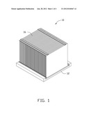
[0008] FIG. 1 is an isometric, assembled view of a heat sink according to an exemplary embodiment of the present disclosure, wherein the heat sink includes a fin unit and a base plate.
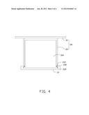
[0009] FIG. 2 is an exploded view of the heat sink of FIG. 1.
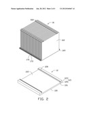
[0010] FIG. 3 is an isometric view of a fin of the fin unit of FIG. 1.
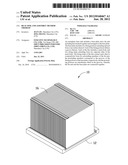
[0011] FIG. 4 is a side view of the heat sink of FIG. 1, showing the fin unit assembled to the base plate by a punch mold.
DETAILED DESCRIPTION
[0012] Reference will now be made to the figures to describe the present heat sink and method in detail.
[0013] Referring to FIG. 1, a heat sink 10 according to a first exemplary embodiment of the present disclosure includes a base plate 12 and a fin unit 16 arranged thereon.
[0014] Referring also to FIG. 2, the base plate 12 is rectangular, and includes a planar bottom surface 120 and a top surface 122. The bottom surface 120 is configured to contact a heat-generating component to absorb heat generated thereby. Two fixing portions 121 extend upwardly from two opposite sides of the top surface 122 of the base plate 12, respectively. Each of the fixing portions 121 extends along a long side edge of the base plate 12. The fixing portions 121 are formed by extrusion, and each includes a vertical wall 123 extending upwardly from the top surface 122 of the base plate 12 and a horizontal wall 125 extending inwardly from a top end of the vertical wall 123 towards the other fixing portion 121. The horizontal wall 125 is substantially parallel to and spaced from the top surface 122 of the base plate 12, to define a groove 126 between the horizontal wall 125 and the top surface 122 of the base plate 12. The groove 126 extends along the long side of the base plate 12. An elongated notch 128 above the groove 126 is defined in an upper surface of the horizontal wall 125.
[0015] The fin unit 16 includes a plurality of fins 160 arranged on the top surface 122 of the base plate 12. Each of the fins 160 is a substantially rectangular thin metallic plate. The fins 160 are parallel. Referring to also to FIG. 3, each of the fins 160 includes a substantially rectangular main body 161, an upper flange 162 and a lower flange 163 respectively extending forward from an upper edge and a lower edge of the main body 161, two fixing strips 166 located at two opposite ends of the lower flange 163, and two pairs of receiving units 168 formed at the upper flange 162 and the lower flange 163, respectively. The lower flange 163 is longer than the upper flange 162, with two ends 1631 extending from a left side and right side of the main body 161. Each of the fixing strips 166 includes a first strip portion 165 extending upward from a corresponding end 1631 of the lower flange 163 and a second strip portion 164 extending inward from a top end of the first strip portion 165 towards the other fixing strip 166. The second strip portion 164 is substantially parallel to and spaced from the lower flange 163. Each of the receiving units 168 includes an L-shaped hook 1681 extending from a long edge of the corresponding upper or lower flange 162, 163, and a receiving hole 1682 defined in the corresponding upper or lower flange 162, 163 adjacent to the hook 1681. In the illustrated embodiment, the receiving hole 1682 is a through slot which is parallel to the long edge of the corresponding upper or lower flange 162, 163.
[0016] Referring back to FIG. 2, when the heat sink 10 is assembled, the fins 160 are stacked together. The upper flanges 162 of each two neighboring fins 160 contact each other to cooperatively define a planar top surface of the fin unit 16, and the lower flanges 163 of each two neighboring fins 160 contact each other to cooperatively define a planar bottom surface of the fin unit 16. For each two neighboring fins 160, the hooks 1681 of the receiving units 168 of a rear fin 160 are received in the receiving holes 1682 of a front fin 160 to connect the two neighboring fins 160. The fixing strips 166 of each two neighboring fins 160 abut each other to cooperatively form two protruding members 169 at two opposite sides of the fin unit 16. More specifically, the first strip portions 165 of the fixing strips 166 are coplanar to form two supporting walls 172 extending upward from two opposite sides of the bottom surface of the fin unit 16; and the second strip portions 164 are coplanar to form two connecting walls 170 connecting top ends of the supporting walls 172 and a corresponding lateral side of the fin unit 16. The protruding members 169 correspond to the grooves 126 of the fixing portions 121 of the base plate 12, respectively.
[0017] In assembly of the heat sink 10, the fin unit 16 is placed at one end of the base plate 12, with the protruding members 169 targeting the grooves 126 of the fixing portions 121, respectively. The fin unit 16 is then mounted onto the base plate 12, with the protruding members 169 received in the grooves 126 of the fixing portions 121, respectively. The connecting wall 170 of each of the protruding members 169 abuts a bottom surface of the horizontal wall 125 of a corresponding fixing portion 121, and the supporting wall 172 of each of the protruding members 169 abuts an inner surface of the vertical wall 123 of the corresponding fixing portion 121.
[0018] Referring to FIG. 4, a punch mold 20 is then provided. The punch mold 20 includes a press plate 21, and two punch plates 22 depending from the press plate 21. Each of the punch plates 22 is substantially rectangular, and forms an edge 221 at a bottom end thereof. A distance between the two punch plates 22 is approximately equal to (slightly greater than) that between the two notches 128 of the fixing portions 121 of the base plate 12. The punch mold 20 is moved over the fin unit 16 to cover the fin unit 16, with the edges 221 of the punch plates 22 received in the notches 128 of the fixing portions 121, respectively. The punch mold 20 is then driven further down to force the horizontal walls 125 of the fixing portions 121 to tightly contact the connecting walls 170 of the protruding members 169 of the fin unit 16, thereby firmly connecting the fin unit 16 and the base plate 12.
[0019] In the process of assembly of the heat sink 10, neither soldering flux nor nickel plating is required during assembly of the fin unit 16 to the base plate 12. The manufacturing cost of the heat sink 10 is minimized, and the assembly of the fins 160 to the base plate 12 is simple and convenient.
[0020] It is to be understood, however, that even though numerous characteristics and advantages of the embodiments have been set forth in the foregoing description, together with details of the structures and functions of the embodiments, the disclosure is illustrative only, and changes may be made in detail, especially in matters of shape, size, and arrangement of parts within the principles of the disclosure to the full extent indicated by the broad general meaning of the terms in which the appended claims are expressed.
User Contributions:
Comment about this patent or add new information about this topic:
| People who visited this patent also read: | |
| Patent application number | Title |
|---|---|
| 20150107626 | Descaling system for heat exchange equipment |
| 20150107625 | DIESEL ENGINE CLEANING SYSTEM AND METHOD |
| 20150107624 | ADHESIVE MATERIAL FOR USE IN RESIDUE CONFIRMATION, AND METHOD FOR CONFIRMATION OF RESIDUE REMAINING ON OBJECT TO BE CLEANED AFTER CLEANING USING THE SAME |
| 20150107623 | IN SITU CLEAN APPARATUS AND METHOD THEREOF |
| 20150107622 | SUBSTRATE LIQUID PROCESSING APPARATUS AND SUBSTRATE LIQUID PROCESSING METHOD |
Images included with this patent application:
 |  |
 |  |
 |
| Similar patent applications: | |
| Date | Title |
|---|---|
| 2009-04-23 | Heat sink system and assembly |
| 2012-01-26 | Heat sink system and assembly |
| 2012-07-26 | Heat sink mount and assembly |
| 2008-11-06 | Re-workable heat sink attachment assembly |
| 2010-07-22 | Fins-type heat sink and method for assembling the same |
| New patent applications from these inventors: | |
| Date | Title |
|---|---|
| 2014-12-18 | Method and device for displaying microblog dynamics, and computer storage medium |
| 2014-09-04 | Method and device for selecting friends in microblogging |
| 2014-05-01 | Search ranking method and system for community users |
| 2013-12-05 | Method for manufacturing light bar that enhances central point brightness of backlight module |
| 2013-05-02 | Electronic device capable of adjusting orientation of display content in response to rotation of a support |
| Top Inventors for class "Heat exchange" | |
| Rank | Inventor's name |
|---|---|
| 1 | Levi A. Campbell |
| 2 | Chun-Chi Chen |
| 3 | Tai-Her Yang |
| 4 | Robert E. Simons |
| 5 | Richard C. Chu |