Patent application title: VENTILATOR
Inventors:
Chun-Chieh Wong (Taipei, TW)
Chen-Yu Wang (Taipei, TW)
IPC8 Class: AF04D2944FI
USPC Class:
4152081
Class name: Rotary kinetic fluid motors or pumps working fluid passage or distributing means associated with runner (e.g., casing, etc.) vane or deflector
Publication date: 2012-05-10
Patent application number: 20120114476
Abstract:
A ventilator includes a first casing, a second casing, a fan blade and a
flow guider. The second casing is connected to the first casing and forms
a flow channel between the first casing and the second casing. The fan
blade is disposed between the first casing and the second casing. When
the fan blade rotates, an air-flow compression zone and an air-flow
decompression zone are formed in the flow channel. The flow guider is
formed along a boundary line to the air-flow decompression zone, wherein
the boundary line is adjacent to the air-flow compression zone and the
air-flow decompression zone. With the ventilator, the air pressure of the
ventilator is increased and noise can be controlled.Claims:
1. A ventilator, comprising: a first casing; a second casing connected to
the first casing and forming a flow channel between the first casing and
the second casing; a fan blade disposed between the first casing and the
second casing, and wherein when the fan blade rotates, an air-flow
compression zone and an air-flow decompression zone are formed in the
flow channel; and a flow guider disposed in the flow channel, the flow
guider is formed along a boundary line to the air-flow decompression
zone, wherein the boundary line is adjacent to the air-flow compression
zone and the air-flow decompression zone.
2. The ventilator according to claim 1, wherein an air inlet is further formed on the first casing or the second casing, and the first casing is connected to the second casing correspondingly to form an air outlet.
3. The ventilator according to claim 2, wherein when the fan blade rotates, an air-flow enters the air inlet, passes through the air-flow compression zone and the air-flow decompression zone, and release out from the air outlet.
4. The ventilator according to claim 2, wherein the flow channel further includes an air-flow outlet zone adjacent to the air outlet, and the flow guider ends before the air-flow outlet zone.
5. The ventilator according to claim 1, wherein the flow guider is disposed at the first casing or the second casing.
6. The ventilator according to claim 1, wherein the flow guider is formed by a concave at the first casing or the second casing.
7. The ventilator according to claim 1, wherein the first casing and the flow guider or the second casing and the flow guider are integratedly formed.
8. The ventilator according to claim 1, wherein the material of the first casing, the second casing and the flow guider is metal, plastic or a combination thereof.
9. The ventilator according to claim 1, wherein the flow guider includes a curved surface.
10. The ventilator according to claim 1, wherein a first height is formed between the first casing and the second casing, the flow guider has a second height, and the first height is higher than the second height.
Description:
CROSS REFERENCE TO RELATED APPLICATIONS
[0001] The Non-provisional application claims priority to U.S. provisional patent application with Ser. No. 61/410,367 filed on Nov. 5, 2010. This and all other extrinsic materials discussed herein are incorporated by reference in their entirety.
BACKGROUND OF THE INVENTION
[0002] 1. Field of Invention
[0003] The invention relates to a ventilator and, more particularly, to a ventilator which increases air pressure.
[0004] 2. Related Art
[0005] As science and research technology develop, electronic devices become lighter and thinner, and people have more demands on functions. For example, a notebook computer is seeking for lighter and thinner products, and thus an effective heat dissipating module is more difficult to design. The dimension of a heat dissipating ventilator should be smaller due to the limitation of inner space, and thus the air pressure and the air volume are relatively low.
[0006] Consequently, two methods are usually taken to increase the air pressure of the heat dissipating ventilator to meet the requirements of the cooling system. One method is to use a wheel blade fan with higher back pressure. The other method is to increase the rotating speed of the ventilator. Both of the two methods can increase the air pressure of the ventilator to improve the heat dissipating efficiency, however, the noise of the ventilator becomes louder.
SUMMARY OF THE INVENTION
[0007] A ventilator is provided to increase the air pressure of the ventilator and improve the heat dissipating efficiency without increasing the noise.
[0008] The ventilator disclosed herein includes a first casing, a second casing, a fan blade and a flow guider.
[0009] The second casing is connected to the first casing and forms a flow channel between the first casing and the second casing. The fan blade is disposed between the first casing and the second casing. When the fan blade rotates, an air-flow compression zone and an air-flow decompression zone are formed in the flow channel. The flow guider is disposed in the flow channel and formed along a boundary line to the air-flow decompression zone, wherein the boundary line is adjacent to the air-flow compression zone and the air-flow decompression zone.
[0010] These and other features, aspects and advantages of the present invention will become better understood with regard to the following description, appended claims, and accompanying drawings.
BRIEF DESCRIPTION OF THE DRAWINGS
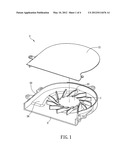
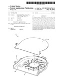
[0011] FIG. 1 is an exploded diagram showing a ventilator in an embodiment;
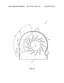
[0012] FIG. 2 is a top view of the ventilator in FIG. 1;
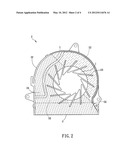
[0013] FIG. 3 is another top view diagram showing the ventilator in FIG. 1; and
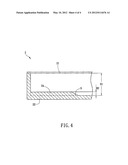
[0014] FIG. 4 is a sectional schematic diagram showing the ventilator along a straight line A-A in FIG. 3.
DETAILED DESCRIPTION OF THE INVENTION
[0015] A ventilator in one embodiment is illustrated with relating figures, and the same symbols denote the same components in different figures.
[0016] FIG. 1 is an exploded diagram showing a ventilator 2 in an embodiment. The ventilator 2 includes a first casing 21, a second casing 22, a fan blade 23 and a flow guider 24.
[0017] The second casing 22 is connected to the first casing 21 and forms a flow channel therebetween. The flow channel is for air-flow to be flowed through. Moreover, an air inlet I is formed at the first casing 21 or the second casing 22, and an air outlet O is formed after the first casing 21 and the second casing 22 are connected.
[0018] In the embodiment, the air inlet I formed on the second casing 22 is taken as an example. In other embodiments, the air inlet I can be formed on the first casing 21 only, or formed both on the first casing 21 and the second casing 22. The term "flow channel" means an area where air flows through after the air-flow enters the air inlet I of the ventilator 2 and before it is exhausted from the air outlet O.
[0019] The fan blade 23 is disposed between the first casing 21 and the second casing 22, and when the fan blade 23 rotates, the air-flow enters the air inlet I and exhausts from the air outlet O.
[0020] FIG. 2 is a top view of the ventilator 2 in FIG. 1. The first casing 21 is not shown in FIG. 2 in order to illustrate the inner structure of the ventilator 2 more clearly.
[0021] When the fan blade 23 rotates, an air-flow compression zone EZ and an air-flow decompression zone DZ are formed in the flow channel of the ventilator 2. When the air enters the air-flow compression zone EZ, the pressure of the air-flow increases due to pressurization by the fan blade 23. Then, the air-flow enters the air-flow decompression zone DZ from the air-flow compression zone EZ. In the air-flow decompression zone DZ, the flow rate of the air-flow increases, but the pressure of the air-flow decreases. Finally, the air-flow is exhausted from the air outlet O to dissipate heat of the electronic device therewith.
[0022] The flow guider 24 is disposed in the flow channel. The flow guider 24 may be connected to the first casing 21 or the second casing 22, or it may be formed by a concave at the first casing 21 or the second casing 22. In other words, the number of the flow guider 24 may be one, and the flow guider 24 is connected to the first casing 21 or the second casing 22, which is not limited herein. In an embodiment, the number of the flow guiders 24 can be two, and the flow guiders 24 are connected to the first casing 21 and the second casing 22, respectively. In the embodiment, the flow guider 24 is connected to an inner side of the second casing 22, and the flow guider 24 and the second casing 22 are integratedly formed.
[0023] If the flow guider 24 is disposed at the first casing 21, the flow guider 24 and the first casing 21 may be integratedly formed. The flow guider 24 also may be locked, attached, fastened or clipped to the first casing 21 and the second casing 22. Moreover, the material of the first casing 21, the second casing 22 and the flow guider 24 may be metal or plastic, or a combination thereof which is not limited herein.
[0024] The flow guider 24 extends along a boundary line L to the air-flow decompression zone DZ, and the boundary line L is formed between the air-flow compression zone EZ and the air-flow decompression zone DZ. In the embodiment, the flow guider 24 is formed or disposed adjacent near the boundary line L that closed to the air-flow compression zone EZ. As shown in FIG. 2, an air-flow outlet zone OZ is further formed at the flow channel. The air-flow outlet zone OZ is near the air outlet O, and the extension of the flow guider 24 ends before the air-flow outlet zone OZ. In other words, the flow guider 24 does not extend to the air-flow outlet zone OZ from the air-flow decompression zone DZ to avoid that a cross section area of the air outlet O decreases due to the flow guider 24 and thereby decreases the air flow of the ventilator 2.
[0025] FIG. 3 is another top view diagram showing the ventilator 2 in FIG. 1. The fan blade 23 has a center point P. An angle θ is formed based on two ends of the flow guider 24 and the center point P (that is, the angle θ is formed between two dotted lines as shown in FIG. 3), and in an embodiment, the angle θ is smaller than 110 degrees. FIG. 4 is a sectional schematic diagram showing the ventilator 2 along a straight line A-A in FIG. 3.
[0026] A first height H1 is formed between the first casing 21 and the second casing 22, and the flow guider 24 has a second height H2. The first height H1 is higher than the second height H2. In the embodiment, a ratio of the second height H2 and the first height H1 is between 0.05 and 0.2.
[0027] The first casing 21 is shown in dotted lines in FIG. 4 in order to show the first height H1. Furthermore, the flow guider 24 includes a curved surface S to stabilize airflow in the flow channel.
[0028] As stated above, the flow guider 24 is illustrated to be set in the flow channel of the ventilator 2, and the flow guider 24 extends along the boundary line L to the air-flow decompression zone DZ. Because the flow guider 24, the space of the flow channel is decreased. Consequently, when the air-flow enters the air-flow decompression zone DZ, the air pressure of the air-flow is maintained, and the decompression slows down. In other words, the flow guider 24 slows down the decompression of the air-flow in the air-flow decompression zone DZ and decreases pressure drop of the air-flow in the ventilator 2.
[0029] According to practical efficiency test, with the same noise value (such as 40 decibels) and the same air volume (such as 4.20 cube feet per minute), the ventilator 2 increases the air pressure by 15% (from 140.4 Pascal to 161.7 Pascal) compared to that of a conventional ventilator. Thus, the ventilator 2 has a higher heat dissipating efficiency.
[0030] The ventilator 2 in the embodiment takes a turn blade fan as an example. The flow guider 24 also may be applied to a wheel blade fan, which is not limited herein.
[0031] Although the present invention has been described in considerable detail with reference to certain preferred embodiments thereof, the disclosure is not for limiting the scope. Persons having ordinary skill in the art may make various modifications and changes without departing from the scope. Therefore, the scope of the appended claims should not be limited to the description of the preferred embodiments described above.
User Contributions:
Comment about this patent or add new information about this topic:
Images included with this patent application:
 |  |
 |  |
 |
| New patent applications in this class: | |
| Date | Title |
|---|---|
| 2022-05-05 | Vane with seal |
| 2018-01-25 | Tidal current energy generating device |
| 2018-01-25 | Multi-segment turbocharger bearing housing and methods therefor |
| 2018-01-25 | Device for conditioning flow of working fluids |
| 2017-08-17 | Airfoil for a gas turbine engine |
| New patent applications from these inventors: | |
| Date | Title |
|---|---|
| 2017-02-16 | Dangerous vehicle warning method and dangerous vehicle warning system |
| 2012-06-07 | Heat dissipating device |
| 2008-08-28 | Communication notification setting method |
| Top Inventors for class "Rotary kinetic fluid motors or pumps" | |
| Rank | Inventor's name |
|---|---|
| 1 | Gabriel L. Suciu |
| 2 | Frederick M. Schwarz |
| 3 | United Technologies Corporation |
| 4 | Brian D. Merry |
| 5 | Craig M. Beers |