Patent application title: ELECTRIC FAN
Inventors:
Ching-Feng Hsu (Taipei Hsien, TW)
IPC8 Class: AF04D2960FI
USPC Class:
416246
Class name: Fluid reaction surfaces (i.e., impellers) support mounting, carrier or fairing structure selectively adjustable impeller mount
Publication date: 2010-11-04
Patent application number: 20100278658
Inventors list |
Agents list |
Assignees list |
List by place |
Classification tree browser |
Top 100 Inventors |
Top 100 Agents |
Top 100 Assignees |
Usenet FAQ Index |
Documents |
Other FAQs |
Patent application title: ELECTRIC FAN
Inventors:
Ching-Feng Hsu
Agents:
PEARNE & GORDON LLP
Assignees:
Origin: CLEVELAND, OH US
IPC8 Class: AF04D2960FI
USPC Class:
Publication date: 11/04/2010
Patent application number: 20100278658
Abstract:
An electric fan has a driving assembly, a stand and an impeller assembly
being connected to and being driven by the driving assembly. The driving
assembly has a positioning panel having multiple indentations and two
connectors being formed on the positioning panel. The stand is mounted
into the driving assembly and around the connector of the driving
assembly and has at least two resilient positioning protrusions engage
two of the indentations of the driving assembly. With the at least two
positioning protrusions engaging different indentations, the driving
assembly and the impeller assembly are pivoted and are held in different
angles. Therefore, the angle of the impeller assembly is easily adjusted.Claims:
1. An electric fan comprising:a driving assembly havinga housing havinga
sidewall;an inner surface;a front end;a through hole being formed through
the outer surface of the housing;a positioning panel protruding from the
inner surface of the housing and havingtwo opposite ends;a positioning
surface facing the through hole of the housing; andmultiple indentations
being formed transversely in the positioning surface adjacent to the ends
of the positioning panel; andtwo connectors being formed on and
protruding from the positioning surface of the positioning panel and
being respectively adjacent to the indentations, and each connector
having a mounting shaft corresponding to and being parallel to the
indentations of the positioning panel; anda motor being mounted in the
housing and having a driving shaft protruding out from the front end of
the housing and having a distal end;an impeller assembly being mounted
securely on the distal end of the driving shaft of the motor; anda stand
being connected to the housing and havinga base; andan arm protruding
upward from the base and havinga top end being mounted through the
through hole of the housing;a mounting recess being formed in the top end
of the arm;two opposite inner surfaces;two pivot recesses being formed
respectively in the inner surfaces of the arm, aligning with each other
and being mounted respectively around the mounting shafts of the
connectors; andat least two positioning protrusions being formed on the
top end of the arm and being resilient, and each one of the at least two
positioning protrusions selectively engaging one of the indentations of
the positioning panel of the housing.
2. The electric fan as claimed in claim 1, wherein the arm of the stand has two half-shells being attached to each other.
3. The electric fan as claimed in claim 1, whereinthe base of the stand has a sidewall;the arm of the stand further hasa bottom end protruding from the sidewall of the base; anda middle extending obliquely and upwardly from the bottom end of the arm; andthe top end of the arm extending from the middle of the arm.
4. The electric fan as claimed in claim 2, whereinthe base of the stand has a sidewall;the arm of the stand further hasa bottom end protruding from the sidewall of the base; anda middle extending obliquely and upwardly from the bottom end of the arm; andthe top end of the arm extending from the middle of the arm.
5. The electric fan as claimed in claim 3, whereinthe housing of the driving assembly further has a limiting edge being defined around the through hole of the housing; andthe top end of the arm selectively abuts the limiting edge of the housing.
6. The electric fan as claimed in claim 4, whereinthe housing of the driving assembly further has a limiting edge being defined around the through hole of the housing; andthe top end of the arm selectively abuts the limiting edge of the housing.
Description:
BACKGROUND OF THE INVENTION
[0001]1. Field of the Invention
[0002]The present invention relates to an electric fan, especially to an electric fan with an easily adjusted impeller assembly.
[0003]2. Description of the Prior Arts
[0004]An electric fan produces airflow and makes a draft. Especially in hot weather, the electric fan dissipates heat around people to make people feel comfortable.
[0005]A conventional electric fan has a stand, an impeller assembly, a connector and a bolt. The connector is attached to the impeller assembly and is mounted pivotally in the stand. The bolt is mounted through the stand and selectively fastens to the connector to hold the impeller assembly in a specific angle or loosens from the connector to allow the impeller assembly to pivot relative to the stand.
[0006]However, loosening the bolt to adjust the angle of the impeller assembly and fastening the bolt to hold the impeller assembly in the specific angle are inconvenient and time consuming. Moreover, connection between the connector and the bolt gradually wear away causing movement of the impeller assembly. Consequently, the impeller assembly is not held in specific positions when the connector and the bolt are worn down.
[0007]To overcome the shortcomings, the present invention provides an electric fan to mitigate or obviate the aforementioned problems.
SUMMARY OF THE INVENTION
[0008]The main objective of the present invention is to provide an easily adjusted electric fan.
[0009]The electric fan has a driving assembly, a stand and an impeller assembly being connected to and being driven by the driving assembly. The driving assembly has a positioning panel having multiple indentations and two connectors being formed on the positioning panel. The stand is mounted into the driving assembly and around the connector of the driving assembly and has at least two resilient positioning protrusions engage two of the indentations of the driving assembly.
[0010]With the at least two positioning protrusions engaging different indentations, the driving assembly and the impeller assembly are pivoted and are held in different angles. Therefore, the angle of the impeller assembly is easily adjusted.
[0011]Other objectives, advantages and novel features of the invention will become more apparent from the following detailed description when taken in conjunction with the accompanying drawings.
BRIEF DESCRIPTION OF THE DRAWINGS
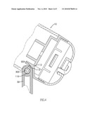
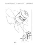
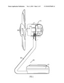
[0012]FIG. 1 is a side view in partial section of an electric fan in accordance with the present invention;
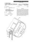
[0013]FIG. 2 is an enlarged exploded perspective view of the electric fan in FIG. 1;
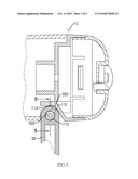
[0014]FIG. 3 is an enlarged cross-sectional side view of the electric fan in FIG. 1;
[0015]FIG. 4 is an enlarged operational cross-sectional side view of the electric fan in FIG. 1; and
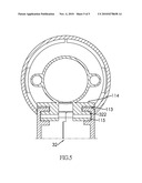
[0016]FIG. 5 is a cross-sectional front view of the electric fan along line 5-5 in FIG. 3.
DETAILED DESCRIPTION OF THE PREFERRED EMBODIMENTS
[0017]With reference to FIG. 1, an electric fan in accordance with the present invention comprises a driving assembly (10), an impeller assembly (20) and a stand (30).
[0018]With further reference to FIG. 2, the driving assembly (10) has a housing (11) and a motor (12).
[0019]The housing (11) has a sidewall, an inner surface, a front end, a through hole (111), a limiting edge, a positioning panel (112) and two connectors (114).
[0020]The through hole (111) is formed through the sidewall of the housing (11). The limiting edge is defined around the through hole (111).
[0021]The positioning panel (112) protrudes from the inner surface of the housing (11) and has two opposite ends, a positioning surface and multiple indentations (113). The positioning surface of the positioning panel (112) faces the through hole (111) of the housing (11). The indentations (113) is formed transversely in the positioning surface adjacent to the ends of the positioning panel (112).
[0022]The connectors (114) are formed on and protrude from the positioning surface of the positioning panel (112) and are respectively adjacent to the indentations (113). Each connector (114) has a mounting shaft (115). The mounting shaft (115) corresponds to and is parallel to the indentations (113) of the positioning panel (112).
[0023]The motor (12) is mounted in the housing (11) and has a driving shaft (121). The driving shaft (121) protrudes out from the front end of the housing (11) and has a distal end.
[0024]The impeller assembly (20) is mounted securely on the distal end of the driving shaft (121) of the motor (12), is driven by the motor (12) and rotates along with the driving shaft (121).
[0025]With further reference to FIGS. 3 and 5, the stand (30) is connected to the housing (11) and has a base (31) and an arm (32). The base (31) has a sidewall.
[0026]The arm (32) protrudes upward from the base (31), may have two half-shells (32A) being attached to each other and has a bottom end, a middle, a top end, a mounting recess (321), two opposite inner surfaces, two pivot recesses (322) and at least two positioning protrusions (323).
[0027]The bottom end protrudes from the sidewall of the base (31). The middle extends obliquely and upwardly from the bottom end of the arm (32). The top end extends from the middle of the arm (32), is mounted through the through hole (111) of the housing (11) and selectively abuts the limiting edge of the housing (11).
[0028]The mounting recess (321) is formed in the top end of the arm (32). The pivot recesses (322) are formed respectively in the inner surfaces of the arm (32), align with each other and are mounted respectively around the mounting shafts (115) of the connectors (114) to allow the driving assembly (10) and the impeller assembly (20) to pivot relative to the stand (30). The at least two positioning protrusions (323) are formed on the top end of the arm (32) and are resilient. Each one of the at least two positioning protrusions (323) selectively engages one of the indentations (113) of the positioning panel (112) of the housing (11).
[0029]With further reference to FIG. 4, the electric fan as described has the following advantage. When the at least two positioning protrusions (323) engage different indentations (113), the driving assembly (10) and the impeller assembly (20) are pivoted and are held in different angles. Therefore, the angle of the impeller assembly (20) is easily adjusted. Moreover, with the arm (32) abutting the limiting edge of the housing (11), a pivot range of the driving assembly (10) is limited.
[0030]Even though numerous characteristics and advantages of the present invention have been set forth in the foregoing description, together with details of the structure and features of the invention, the disclosure is illustrative only. Changes may be made in the details, especially in matters of shape, size, and arrangement of parts within the principles of the invention to the full extent indicated by the broad general meaning of the terms in which the appended claims are expressed.
User Contributions:
comments("1"); ?> comment_form("1"); ?>Inventors list |
Agents list |
Assignees list |
List by place |
Classification tree browser |
Top 100 Inventors |
Top 100 Agents |
Top 100 Assignees |
Usenet FAQ Index |
Documents |
Other FAQs |
User Contributions:
Comment about this patent or add new information about this topic:
Images included with this patent application:
 |  |
 |  |
 |  |
| New patent applications in this class: | |
| Date | Title |
|---|---|
| 2015-01-15 | Ceiling fan tilt bracket |
| 2014-10-02 | Wind turbine defense |
| 2011-12-08 | Horizontal axis wind turbine |
| 2011-09-29 | Hybrid ram air turbine |
| 2011-09-22 | Stow abort mechanism for a ram air turbine |
| Top Inventors for class "Fluid reaction surfaces (i.e., impellers)" | |
| Rank | Inventor's name |
|---|---|
| 1 | Frank B. Stamps |
| 2 | Ching-Pang Lee |
| 3 | Gabriel L. Suciu |
| 4 | Stefan Herr |
| 5 | Tracy A. Propheter-Hinckley |