Patent application title: Belt tension indicator
Inventors:
Michael L. King (Weatherford, TX, US)
IPC8 Class: AB65G4300FI
USPC Class:
1985021
Class name: Conveyors: power-driven with alarm or indicator
Publication date: 2010-11-04
Patent application number: 20100276252
Inventors list |
Agents list |
Assignees list |
List by place |
Classification tree browser |
Top 100 Inventors |
Top 100 Agents |
Top 100 Assignees |
Usenet FAQ Index |
Documents |
Other FAQs |
Patent application title: Belt tension indicator
Inventors:
Michael L. King
Agents:
SIEMENS CORPORATION;INTELLECTUAL PROPERTY DEPARTMENT
Assignees:
Origin: ISELIN, NJ US
IPC8 Class: AB65G4300FI
USPC Class:
Publication date: 11/04/2010
Patent application number: 20100276252
Abstract:
A method for verifying belt tension on a conveyor mechanism that includes
a belt mounted under tension on rollers, includes steps of measuring
selected physical status parameters associated with the conveyor
mechanism and determining if the belt has reached a predetermined level
of tension indirectly from such status parameters without direct
measurement of belt tension.Claims:
1. An apparatus for verifying belt tension on a conveyor mechanism that
includes a belt mounted under tension on rollers, comprising a bladder
pressurized by internal gas pressure mounted in a position proximate the
belt;a monitoring roller assembly in engagement with a surface of the
belt whereby tension of the belt causes the belt to exert force against
the bladder through the monitoring roller assembly; andan indicator which
shows when the tension of the belt is at a target level.
2. The apparatus of claim 1, wherein the indicator comprises a monitoring stem which assumes an extended position when the belt tension is at the target level.
3. The apparatus of claim 1, wherein the monitoring roller assembly includes a pivot at one end portion thereof whereby pivoting of the monitoring roller assembly in a predetermined direction causes by tension of the belt force to be exerted by the monitoring roller assembly against the bladder.
4. The apparatus of claim 1, wherein the indicator comprises a pressure transducer in communication with a pressurized interior of the bladder, and a transmitter that that sends a signal from the pressure transducer indicating that the tension of the belt is at the target level.
5. A method for verifying belt tension on a conveyor mechanism that includes a belt mounted under tension on rollers, comprising measuring selected physical status parameters associated with the conveyor mechanism; anddetermining if the belt has reached a predetermined level of tension indirectly from such status parameters without direct measurement of belt tension.
Description:
[0001]This application claims priority of U.S Provisional Application No.
61/173,330 filed Apr. 28, 2009.
FIELD OF THE INVENTION
[0002]This invention relates to a system and method for indicating the tension of a belt of the kind used in pinch belt conveyor systems used in postal sorting machines
BACKGROUND OF THE INVENTION
[0003]A number of prior inventions provide a method and system for sorting flat mail wherein maintaining proper belt tension is important to maintaining sorting efficiency and avoiding misfeeds and other sorting errors. It is known for example to provide for an alarm when a misfeed is detected. See for example United States Patent Application 20050285323, Dec. 29, 2005. Detection devices used in sorting equipment are generally designed to detect abnormal conditions and failures of different kinds.
SUMMARY OF THE INVENTION
[0004]An apparatus for verifying belt tension according to the invention comprises a conveyor mechanism that includes a belt mounted under tension on rollers; a bladder pressurized by internal gas pressure in a position proximate the belt; a monitoring roller assembly in engagement with a surface of the belt whereby tension of the belt causes the belt to exert force against the bladder through the monitoring roller assembly and an indicator which shows when the tension of the belt is at a target level.
[0005]The invention further provides a method for verifying belt tension on a conveyor mechanism that includes a belt mounted under tension on rollers, comprising measuring selected physical status parameters associated with the conveyor mechanism, and determining if the belt has reached a predetermined level of tension indirectly from such status parameters without direct measurement of belt tension.
BRIEF DESCRIPTION OF THE DRAWINGS
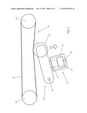
[0006]FIG. 1 is a schematic diagram of an apparatus according to the invention in an operative position indicating that the belt tension is below the target level;
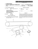
[0007]FIG. 2 is a schematic diagram of an apparatus according to the invention as shown in FIG. 1 in an operative position indicating that the belt tension at or above the target level; and
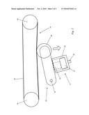
[0008]FIG. 3 is a schematic diagram of an alternate apparatus according to the invention in an operative position indicating that the belt tension is at or above a target level.
DETAILED DESCRIPTION
[0009]A belt conveyor 10 is of the type suitable for transporting a series of flat mail pieces in a postal sorting machine such as DBCS and MLOCR machines includes a belt tension indicator 12 according to the invention. Tensioning of the pinch belt 14 will cause the belt 14 to try and assume a straight line between the two fixed rollers 16, thus exerting force on a monitoring roller assembly 18 which includes a roller 20 which engages the underside of belt 14. As belt 14 is tensioned, it will cause a monitoring roller assembly 18 swings about a pivot 19 to exert force in the direction of the arrow against an air bladder 22. Assembly 18 is configured so that a pusher 23 slidably mounted in a frame 24 exerts such force on bladder 22. In the embodiment of FIG. 1, then the tension of belt 14 is at the desired level pusher 23 exerts force against bladder 22 which causes an indicator 36 to show that the required belt tension has been achieved. Bladder 22 causes an indicator 26 in the form of a tube to pop out in the same manner as is known for use in conventional tires. The present invention uses this form of air pressure gauge in a manner that correlates with belt tension in a manner not practiced in the prior art and which determines belt tension indirectly, i.e. by derivation from other known quantities of the system rather than by a sensor which directly measures belt tension. Indeed the relationship between bladder pressure and belt tension provides a simple mechanism according to the invention. FIG. 3 provides an alternate embodiment of the invention wherein an electronic pressure sensor 28 is connected to a processor 30 so that the processor can light an LED typically at a remote location (a control room or panel) when the belt tension is at the desired level and the processor can monitor the tension of the belt.
[0010]Although several embodiments of the present invention have been described in the foregoing detailed description and illustrated in the accompanying drawings, it will be understood by those skilled in the art that the invention is not limited to the embodiments disclosed but is capable of numerous rearrangements, substitutions and modifications without departing from the spirit of the invention. Such modifications are within the scope of the invention as expressed in the appended claims. Connections between parts that fit together as shown in the drawings are loose enough to permit the limited movements shown without mechanical interference.
User Contributions:
comments("1"); ?> comment_form("1"); ?>Inventors list |
Agents list |
Assignees list |
List by place |
Classification tree browser |
Top 100 Inventors |
Top 100 Agents |
Top 100 Assignees |
Usenet FAQ Index |
Documents |
Other FAQs |
User Contributions:
Comment about this patent or add new information about this topic:
Images included with this patent application:
 |  |
 |  |
| Similar patent applications: | |
| Date | Title |
|---|---|
| 2010-09-16 | Belt scraper tensioning assembly |
| 2008-10-02 | Belt loader extension ramp |
| 2009-12-24 | Belt retention guide |
| 2010-09-16 | Shaft-hub assembly with expansion element |
| 2010-11-04 | Tensioning device for drag conveyor |
| New patent applications in this class: | |
| Date | Title |
|---|---|
| 2016-07-14 | Conveyor module, conveyor mat or chain, method for monitoring wear of a conveyor element, and conveyor system |
| 2016-04-21 | Linear wave motion conveyor |
| 2016-04-14 | Conveyor device with variable angle adjustment |
| 2016-03-31 | Workpiece carrier |
| 2016-03-17 | Conveyor carriage position monitoring |
| Top Inventors for class "Conveyors: power-driven" | |
| Rank | Inventor's name |
|---|---|
| 1 | Matthew L. Fourney |
| 2 | Miguel Angel Gonzalez Alemany |
| 3 | Clifford Theodore Papsdorf |
| 4 | Wouter Balk |
| 5 | Uwe Schneider |