Patent application title: Closed-circuit hydraulic propeller
Inventors:
Essam Tawfik Marcus (Morrisville, NC, US)
IPC8 Class: AF04D1306FI
USPC Class:
4174231
Class name: Motor driven electric or magnetic motor rotary motor and rotary nonexpansible chamber pump
Publication date: 2010-03-25
Patent application number: 20100074778
Inventors list |
Agents list |
Assignees list |
List by place |
Classification tree browser |
Top 100 Inventors |
Top 100 Agents |
Top 100 Assignees |
Usenet FAQ Index |
Documents |
Other FAQs |
Patent application title: Closed-circuit hydraulic propeller
Inventors:
Essam Tawfik Marcus
Agents:
Essam T. Awdalla
Assignees:
Origin: MORRISVILLE, NC US
IPC8 Class: AF04D1306FI
USPC Class:
4174231
Patent application number: 20100074778
Abstract:
The present invention provides closed-circuit hydraulic propeller used for
the generation of thrust, or lift, force from the torque provided by a
prime mover, or a motor, with said thrust, or lift, force being utilized
in propelling, or lifting, a movable vehicle. In a preferred embodiment
the closed-circuit hydraulic propeller comprises an outer casing; two
inner-members; an intermediate body; a drive shaft; a rotor assembly
including at least one central disk and a plurality of circumferentially
arranged thrust, or lift, generating, blades; and an incompressible fluid
completely filling the space enclosed within the casing. In operation,
the incompressible fluid will circulate within the passages confined
between the opposing surfaces of the casing, inner-members, and
intermediate body due to its acceleration by the rotor blades, with the
blades' generated thrust force being transmitted to the propeller's
casing through thrust bearing arrangement(s) Means for cooling the
incompressible viscous fluid are also provided.Claims:
1. A closed-circuit hydraulic propeller comprising:an assembly having a
generally oval-shaped outer casing portion, a first inner-member portion,
and a second inner-member portion, the outer casing structurally supports
and encloses other propeller elements positioned therein, and the outer
surface of each of the inner-members partially defines a closed-circuit
fluid flow passage within the propeller;a drive shaft supported for
rotation in a given direction inside the outer casing by an arrangement
of bearings and extending to a drive receiving end located outside the
outer casing;a rotor secured for rotation with the drive shaft and lying
in a plane normal to the rotational axis of the drive shaft, said rotor
includes at least one central disk and a plurality of circumferentially
arranged thrust, or lift, generating, blades, each blade has an inner
edge attached to the central disk, an outer edge, a leading edge, and a
trailing edge; andan incompressible viscous fluid completely filling the
space enclosed within the outer casing.
2. The closed-circuit hydraulic propeller of claim 1, which further comprises an intermediate-body fixedly attached to the outer casing and located intermediate of the outer casing and the inner-members, with the opposing surfaces of said intermediate-body and said outer casing defining an outer annular passage therebetween, and with the opposing surfaces of said intermediate-body and said inner-members defining an inner annular passage therebetween, with the said rotor blades being positioned for rotation within the said inner annular passage, and with the said intermediate body being configured to allow the flow of the said incompressible viscous fluid from the said outer annular passage to the said upstream inflowing portion of the inner annular passage and from the said downstream outflowing portion of the inner annular passage to the said outer annular passage.
3. The closed-circuit hydraulic propeller of claim 1, which further comprises a generally cylindrical shaped intermediate-body fixedly attached to the outer casing and located intermediate of the outer casing and the inner-members, with the opposing surfaces of said intermediate-body and said outer casing defining an outer annular passage therebetween, and with the opposing surfaces of said intermediate-body and said inner-members defining an inner annular passage therebetween, said inner annular passage has an upstream inflowing converging portion and a downstream outflowing diverging portion, with the said rotor blades being positioned for rotation within the said inner annular passage, and with the said intermediate body being configured to allow the flow of the said incompressible viscous fluid from the said outer annular passage to the said upstream inflowing portion of the inner annular passage and from the said downstream outflowing portion of the inner annular passage to the said outer annular passage.
4. The closed-circuit hydraulic propeller of claim 1, wherein each of the said inner-members being generally hourglass in shape.
5. The closed-circuit hydraulic propeller of claim 1, wherein the downstream outflowing portion of the inner annular passage is provided with at least one set of circumferentially arranged vanes to align the flow of the working fluid within the outflowing portion of the inner annular passage during operation.
6. The closed-circuit hydraulic propeller of claim 1, wherein the number of the blades of the said propeller's rotor ranges between 2 and 36 blades.
7. The closed-circuit hydraulic propeller of claim 1, wherein each two successive blades of the said propeller's rotor are separated by an intervening gap.
8. The closed-circuit hydraulic propeller of claim 7, wherein the ratio between the mean width of each of the said gaps and the mean Chord length of each of the said blades ranges between 0.5:1 and 3:1, and more preferably ranges between 1:1 and 2:1.
9. The closed-circuit hydraulic propeller of claim 1, wherein the successive parts of each of the blades of the said propeller's rotor has the same angle of attack, with said angle of attack ranging between 2 degrees and 14 degrees, and more preferably between 2 degrees and 10 degrees.
10. The closed-circuit hydraulic propeller of claim 1, wherein the successive parts of each of the blades of the said propeller's rotor has gradually increasing angles of attack from the blade's outer edge to the blade's inner edge, with said angles of attack lying anywhere between 2 degrees and 14 degrees and more preferably between 2 degrees and 10 degrees.
11. The closed-circuit hydraulic propeller of claim 1, wherein seal means are provided between the opposing surfaces of the said drive shaft and the said outer casing.
12. The closed-circuit hydraulic propeller of claim 1, wherein means for cooling the said incompressible viscous fluid are provided.
13. The closed-circuit hydraulic propeller of claim 12, wherein the said means provided for cooling the said incompressible viscous fluid comprises a plurality of cooling ribs on the outer surface of the said propeller's outer casing
14. The closed-circuit hydraulic propeller of claim 12, wherein the said means provided for cooling the said incompressible viscous fluid comprises a forced air or fluid cooling arrangement.
15. The closed-circuit hydraulic propeller, of claim 1, wherein the thrust force generated by the said propeller's rotor is transmitted to the said propeller's casing through at least one thrust bearing arrangement.
16. The closed-circuit hydraulic propeller of claim 1, wherein the said propeller's drive shaft is driven by at least one prime mover.
17. The closed-circuit hydraulic propeller of claim 16, wherein the torque supplied by the said prime mover is transmitted to the said propeller's drive shaft through a gear train arrangement.
18. The closed-circuit hydraulic propeller of claim 1, wherein the said propeller's drive shaft is driven by at least one electric motor.
19. The closed-circuit hydraulic propeller of claim 18, wherein the torque supplied by the said electric motor is transmitted to the said propeller's drive shaft through a gear train arrangement.
20. The closed-circuit hydraulic propeller of claim 18, wherein the driving electric current for the said electric motor is supplied from at least one rechargeable electricity storage system; a fuel cell; an electric generator driven by a prime mover; or any combination thereof.
Description:
FIELD OF THE INVENTION
[0001]The present invention relates to a closed-circuit hydraulic propeller, and more particularly to a thrust, or lift, force generating hydraulic propeller with which the torque provided by a prime mover, or a motor, can be utilized efficiently in generating thrust, or lift, force, with said generated force being used for propelling, or lifting, a movable vehicle.
BACKGROUND OF THE INVENTION
[0002]The use of properly shaped and properly angled foils for the efficient generation of lift forces on the wings of airplanes; the rotor blades of helicopters; and hydrofoils has been known in the art for decades, with Lift/Drag ratios ranging between 10/1 and 65/1 being attainable. However, applying the same principal for the efficient conversion of the torque provided by a prime mover, or a motor, into a thrust force through the blades of propellers and ducted fans used for propelling different types of vehicles is not practically feasible due to the relative drop in the efficiency of the thrust force generated by the foils when operating in non-stagnant upstream working fluid conditions.
[0003]And thus, in spite of the well known high efficiency of properly designed, and properly angled; foils in generating lift, or thrust, forces, yet, their use for the efficient generation of thrust force to drive land vehicles, and the like, has been hindered by these before-mentioned limiting factor.
SUMMARY OF THE INVENTION
[0004]The present invention provides a closed-circuit hydraulic propeller to be used for the efficient generation of thrust, or lift, force, utilizing the torque provided by a prime mover, or a motor, with said generated force being used in propelling, or lifting, a movable land, sea, or air vehicle.
[0005]The present invention also provides a closed-circuit hydraulic propeller with which the amount of generated thrust, or lift, force may be flexibly changes within a relatively wide range.
[0006]In a preferred embodiment, the closed-circuit hydraulic propeller comprises: an assembly having a generally oval-shaped outer casing portion, a first inner-member portion, and a second inner-member portion, the outer casing structurally supports and encloses other propeller elements positioned therein, and the outer surface of each of the inner-members partially defines a closed-circuit fluid flow passage within the propeller; a drive shaft supported for rotation in a given direction inside the outer casing by an arrangement of bearings, and extending to a drive receiving end located outside the outer casing; a rotor secured for rotation with the drive shaft and lying in a plane normal to the rotational axis of the drive shaft, said rotor includes at least one central disk and a plurality of circumferentially arranged thrust, or lift, generating, blades, each blade has an inner edge attached to the central disk, an outer edge, a leading edge, and a trailing edge; and an incompressible viscous fluid completely filling the space enclosed within the outer casing.
[0007]In another preferred embodiment, the closed-circuit hydraulic propeller further comprises an intermediate-body fixedly attached to the outer casing and located intermediate of the outer casing and the inner-members, with the opposing surfaces of said intermediate-body and said outer casing defining an outer annular passage therebetween, and with the opposing surfaces of said intermediate-body and said inner-members defining an inner annular passage therebetween, with the said rotor blades being positioned for rotation within said inner annular passage, and with said intermediate body being configured to allow the flow of the said incompressible viscous fluid from said outer annular passage to the upstream inflowing portion of the inner annular passage and from the downstream outflowing portion of the inner annular passage to said outer annular passage.
[0008]In yet another preferred embodiment, the closed-circuit hydraulic propeller further comprises a generally cylindrical shaped intermediate-body fixedly attached to the outer casing and located intermediate of the outer casing and the inner-members, with the opposing surfaces of said intermediate-body and said outer casing defining an outer annular passage therebetween, and with the opposing surfaces of said intermediate-body and said inner-members defining an inner annular passage therebetween, said inner annular passage has an upstream inflowing converging portion and a downstream outflowing diverging portion, with said rotor blades being positioned for rotation within the said inner annular passage, and with the said intermediate body being configured to allow the flow of said incompressible viscous fluid from said outer annular passage to said upstream inflowing portion of the inner annular passage and from said downstream outflowing portion of the inner annular passage to said outer annular passage.
[0009]In a preferred embodiment, each of the inner-members is generally hourglass in shape. In another preferred embodiment, the downstream outflowing portion of the inner annular passage is provided with at least one set of circumferentially arranged vanes to align the flow of the working fluid within the outflowing portion of the inner annular passage during operation.
[0010]The number of the blades of the rotor may range between 2 and 36 blades, depending on the amount of thrust, or lift, force to be generated by the propeller. Each two successive blades are separated from each other by an intervening gap, with the ratio between the mean width of each of the gaps and the mean Chord length of each of the blades (the Gap/Blade ratio or G/B ratio) being determined according to the desired degree of deceleration of the working fluid within the downstream outflowing portion of the inner annular passage during operation, noting that the degree of deceleration will be proportional to the G/B ratio. In a preferred embodiment, the G/B ratio ranges between 0.5:1 and 3:1. In another preferred embodiment, the G/B ratio ranges between 1:1 and 2:1.
[0011]The successive parts of each blade are either designed with the same angle of attack, or designed with gradually increasing angles of attack from the blade's outer edge to the blade's inner edge, so that the downstream flow of the working fluid will be homogenized in terms of total pressure. The blades cross sectional configuration and the angle of attack, or the selected range of angles of attacks, is chosen to provide optimum overall blade lift/drag ratio. Accordingly, in a preferred embodiment the angle of attack, or the angles of attacks of the successive parts of each blade, is/are chosen within a range of angles lying anywhere between 2 degrees and 14 degrees, and in a more preferred embodiment, the angle(s) of attack are chosen within a range of angles lying anywhere between 2 degrees and 10 degrees. Such design considerations are well known by people experienced in the Art.
[0012]In a preferred embodiment, means for cooling the working fluid are provided. Said means may either provide passive cooling via a plurality of cooling ribs on the outer surface of the propeller's casing, or provide active cooling by forced air or fluid cooling arrangements.
[0013]The rotor is either manufactured as a whole by forging or casting, or, the central disk of the rotor is forged or casted separately, with each blade, or each group of blades, being forged or casted separately, followed by assembling the rotor. Such manufacturing and assembling techniques are also well known by people experienced in the Art.
[0014]The thrust, or lift, force generated by the propeller's rotor is transmitted to the propeller's casing through one, or more than one, thrust bearing arrangements. Non limiting examples of thrust bearing arrangements for use include: fixed-geometry thrust bearings; and tilting pad thrust bearings.
[0015]In a preferred embodiment, the means provided for driving the propeller's rotor comprises a prime mover, with the torque supplied by the prime mover transmitted to the propeller's drive shaft either directly, or indirectly through a gear train arrangement. In another preferred embodiment, the means provided for driving the propeller's rotor comprises an electric motor, with the torque supplied by it being transmitted to the propeller's drive shaft either directly, or indirectly through gear train arrangement, and with the electric motor's driving electric current being supplied from: at least one rechargeable electricity storage system, e.g. an electric battery or an ultracapacitor; a fuel cell; an electric generator driven by a prime mover; or any combination thereof.
[0016]In a preferred embodiment, an even number of propellers is used, i.e. the propellers are arranged in one or more pairs, with each pair of propellers having counter-rotating rotors, to balance out the torque effect developed by their rotating components during operation.
DETAILED DESCRIPTION OF THE DRAWINGS
[0017]The description of the objects, features and advantages of the present invention, will be more fully appreciated by reference to the following detailed description of the exemplary embodiments in accordance with the accompanying drawings, wherein:
[0018]FIG. 1 is a sectional view in a schematic representation of an exemplary embodiment of a closed-circuit hydraulic propeller, in accordance with the present invention.
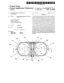
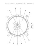
[0019]FIG. 2 is a cross sectional view, taken at the plane of line 2-2 in FIG. 1.
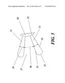
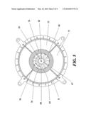
[0020]FIG. 3 is an enlarged view of two successive blades of the rotor of the embodiment of FIG. 1.
[0021]FIG. 4 is a sectional view in a schematic representation of another exemplary embodiment of a closed-circuit hydraulic propeller, in accordance with the present invention.
[0022]FIG. 5 is a cross sectional view, taken at the plane of line 5-5 in FIG. 4.
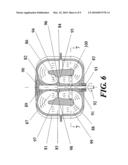
[0023]FIG. 6 is a sectional view in a schematic representation of another exemplary embodiment of a closed-circuit hydraulic propeller, in accordance with the present invention.
[0024]FIG. 7 is a cross sectional view, taken at the plane of line 7-7 in FIG. 6.
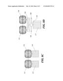
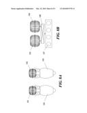
[0025]FIGS. 8A-D are schematic representation of different closed-circuit hydraulic propellers-driving mechanism layouts in accordance with the present invention.
DETAILED DESCRIPTION OF THE INVENTION
[0026]FIG. 1 is a sectional view in a schematic representation of an exemplary embodiment of a closed-circuit hydraulic propeller, in accordance with the present invention.
[0027]The closed-circuit hydraulic propeller comprises: an assembly having a generally oval-shaped outer casing portion (11), a first inner-member portion (12), and a second inner-member portion (13), the outer casing (11) structurally supports and encloses other propeller elements positioned therein, and the outer surface of each of the inner-members (12,13) partially defines a closed-circuit fluid flow passage within the propeller; a drive shaft (14) supported for rotation in a given direction inside the outer casing (11) by an arrangement of bearings (15,16) and extending to a drive receiving end (17) located outside the outer casing, with seal means (18) being provided between the opposing surfaces of the shaft and the outer casing; a rotor (19) secured for rotation with the drive shaft (14) and lying in a plane normal to the rotational axis of the drive shaft, said rotor includes a central disk (20) and a plurality of circumferentially arranged thrust, or lift, generating, blades (21), and as also shown in FIG. 2, which is a cross sectional view taken at the plane of line 2-2 in FIG. 1, each blade has an inner edge (22) attached to the central disk (20), an outer edge (23), a leading edge (24), and a trailing edge (25); and an incompressible viscous fluid (26) completely filling the space enclosed within the outer casing (11).
[0028]In this embodiment, the number of the blades (21) of the rotor is 10 blades, with each two successive blades being separated from each other by an intervening gap (27), and as also shown in FIG. 3, which is an enlarged view of two successive blades of the rotor of the embodiment of FIG. 1, the ratio between the mean width (28) of each of the gaps (27) and the mean Chord length (29) of each of the blades (21), i.e. the Gap/Blade ratio or G/B ratio is 2:1. As described herein above, the number of the blades of the rotor may range between 2 and 36 blades, depending on the amount of thrust, or lift, force to be generated by the propeller, with the used G/B ratio preferably lying anywhere between 0.5:1 and 3:1, and more preferably lying anywhere between 1:1 and 2:1.
[0029]In this embodiment, the successive parts of each blade (21) have the same angle of attack. However, in other preferred embodiments, the blades may be designed with gradually increasing angles of attack from the blades outer edges to the blades inner edges, so that the downstream flow of the working fluid will be homogenized in terms of total pressure. The blades cross sectional configuration and the selected angle(s) of attacks is chosen to provide optimum overall blade lift/drag ratio. Accordingly, in a preferred embodiment the angle of attack, or the angles of attacks of the successive parts of each blade, is/are chosen within a range of angles lying anywhere between 2 degrees and 14 degrees, and in a more preferred embodiment, the angle(s) of attack are chosen within a range of angles lying anywhere between 2 degrees and 10 degrees. Such design considerations are well known by people experienced in the Art.
[0030]The rotor (19) is either manufactured as a whole by forging or casting, or, the central disk (20) of the rotor is forged or casted separately, with each blade (21), or each group of blades, being forged or casted separately, followed by assembling the rotor. Such manufacturing and assembling techniques are also well known by people experienced in the Art.
[0031]The thrust, or lift, force generated by the propeller's rotor (19) is transmitted to the propeller's casing (11) through one, or more than one, thrust bearing arrangement (15). Non limiting examples of thrust bearing arrangements for use include: fixed-geometry thrust bearings; and tilting pad thrust bearings.
[0032]In this embodiment, the outer surface of the propeller's casing (11) is provided with a plurality of cooling ribs (30) to cool the working fluid (26) during operation. However, in other preferred embodiments, the working fluid may be actively cooled by a forced air or fluid cooling arrangements.
[0033]In operation, the working fluid (26) will be accelerated by the rotating downstream displacing surfaces of the blades (21), noting that the vectors of the accelerated working fluid by each two adjacent blades will be separated from each other due to the gap (27) between the blades. This separation between the vectors of the accelerated working fluid along with the viscosity of the working fluid will lead to deceleration of the working fluid, along with partial damping of its non-axial vector components, so that the main bulk of the kinetic energy added to the working fluid (26) through acceleration by the blades (21) will be dissipated and converted into heat.
[0034]The decelerated working fluid will be directed to the upstream portion of the fluid flow passage, where it will be accelerated by the effect of the suction force generated on the rotating upstream suction surfaces of the blades (21).
[0035]The net thrust, or lift, force provided by the closed-circuit hydraulic propeller of the present invention will be equivalent to the total thrust, or lift, force generated by the blades (21) minus the net reaction force acting on the walls defining the curved parts (31) of the inner walls of the casing (11), and thus, to maximize the net thrust, or lift, force we need to optimize the total thrust, or lift, force generated by the blades (21) and minimize the net reaction force acting on the walls defining the curved parts (31) of the inner walls of the casing (11).
[0036]Optimizing the total thrust, or lift, force generated by the blades (21) is provided by selecting the proper blades cross-sectional profile; the optimum angle(s) of attack for use with the selected blades cross-sectional profile; and the proper type of incompressible viscous working fluid (26) having relatively high boiling point and relatively high dynamic viscosity.
[0037]Minimizing the net reaction force acting on the walls confining the curved parts (31) of the fluid passage is provided by bringing down the kinetic energy within the working fluid (26) to a minimum before it is deflected by the inner walls of the casing (11). This will depend on the configuration of the propeller's casing (11); the G/B ratio; and the viscosity of the working fluid (26).
[0038]FIG. 4 is a sectional view in a schematic representation of another exemplary embodiment of a closed-circuit hydraulic propeller, in accordance with the present invention.
[0039]The closed-circuit hydraulic propeller comprises: an assembly having a generally oval-shaped outer casing portion (51), a first inner-member portion (52), and a second inner-member portion (53), the outer casing (51) structurally supports and encloses other propeller elements positioned therein, and the outer surface of each of the inner-members (52,53) partially defines a closed-circuit fluid flow passage within the propeller; an intermediate-body (54) fixedly attached to the outer casing and located intermediate of the outer casing (51) and the inner-members (52,53), with the opposing surfaces of said intermediate-body and said outer casing defining an outer annular passage (55) therebetween, and with the opposing surfaces of said intermediate-body and said inner-members defining an inner annular passage (56) therebetween, said inner annular passage has an upstream inflowing converging portion (57) and a downstream outflowing diverging portion (58); a drive shaft (59) supported for rotation in a given direction inside the outer casing (51) by an arrangement of bearings (60,61) and extending to a drive receiving end (62) located outside the outer casing, with seal means (63) being provided between the opposing surfaces of the shaft and the outer casing; a rotor (64) secured for rotation with the drive shaft (59) and lying in a plane normal to the rotational axis of the drive shaft, said rotor includes a central disk (65) and a plurality of circumferentially arranged thrust, or lift, generating, blades (66), said blades are positioned for rotation within said inner annular passage (56), and as also shown in FIG. 5, which is a cross sectional view taken at the plane of line 5-5 in FIG. 4, each blade has an inner edge (67) attached to the central disk (65), an outer edge (68), a leading edge (69), and a trailing edge (70); and an incompressible viscous fluid (71) completely filling the space enclosed within the outer casing (51), with said intermediate body (54) being configured to allow the flow of said incompressible viscous fluid (71) from said outer annular passage (55) to said upstream inflowing portion of the inner annular passage (57) and from said downstream outflowing portion of the inner annular passage (58) to said outer annular passage (55).
[0040]In this embodiment, the number of the blades (66) of the rotor is 12 blades, with each two successive blades being separated from each other by an intervening gap, with the G/B ratio being 1.5:1, and with the other blade design parameters and other propeller's design and manufacturing considerations being similar to the ones described herein above in reference to the embodiment of FIG. 1.
[0041]In operation, the working fluid (71) will be accelerated by the rotating downstream displacing surfaces of the blades (66), noting that the vectors of the accelerated working fluid by each two adjacent blades will be separated from each other due to the gap between the blades. This separation between the vectors of the accelerated working fluid along with the viscosity of the working fluid and the diverging configuration of the downstream outflowing portion of the inner annular passage (58) will lead to deceleration of the working fluid, along with partial damping of its non-axial vector components. The axial length measurement of the downstream outflowing portion of the inner annular passage (58) and its configuration are chosen to allow for optimum deceleration of the working fluid, so that the main bulk of the kinetic energy added to the working fluid (71) through acceleration by the blades (66) will be dissipated and converted into heat.
[0042]The decelerated working fluid will be directed to the upstream inflowing portion of the inner annular passage (57) through the outer annular passage (55), noting that the outer annular passage (55) slightly diverges along the direction of the flow of the working fluid to compensate for the deceleration of the working fluid within it.
[0043]Within the upstream inflowing portion of the inner annular passage (57) the working fluid (71) will be accelerated by the effect of the suction force generated on the rotating upstream suction surfaces of the blades (66), with the inflowing portion of the inner annular passage (57) being configured to allow for smooth acceleration of the working fluids (71) within it.
[0044]The net thrust, or lift, force provided by the closed-circuit hydraulic propeller of the present invention will be equivalent to the total thrust, or lift, force generated by the blades (66) minus the net reaction force acting on the walls defining the curved parts (72) of the outer annular passage (55), and thus, to maximize the net thrust, or lift, force we need to optimize the total thrust, or lift, force generated by the blades (66) and minimize the net reaction force acting on the walls defining the curved parts (72) of the outer annular passage (55).
[0045]Optimizing the total thrust, or lift, force generated by the blades (66) is provided by selecting the proper blades cross-sectional profile; the optimum angle(s) of attack for use with the selected blades cross-sectional profile; and the proper type of incompressible viscous working fluid (71) having relatively high boiling point and relatively high dynamic viscosity.
[0046]Minimizing the net reaction force acting on the walls confining the curved parts (72) of the fluid passage is provided by bringing down the kinetic energy within the working fluid (71) to a minimum before it is deflected by the inner walls of the casing (51). This will depend on the configuration of the downstream outflowing portion of the inner annular passage (58); the G/B ratio; and the viscosity of the working fluid (71).
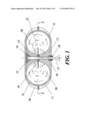
[0047]FIG. 6 is a sectional view in a schematic representation of another exemplary embodiment of a closed-circuit hydraulic propeller, in accordance with the present invention.
[0048]The closed-circuit hydraulic propeller comprises: an assembly having a generally oval-shaped outer casing portion (81), a first inner-member portion (82), and a second inner-member portion (83), the outer casing (81) structurally supports and encloses other propeller elements positioned therein, and the outer surface of each of the inner-members (82,83) partially defines a closed-circuit fluid flow passage within the propeller, with each of the inner-members being generally hourglass in shape; a generally cylindrical shaped intermediate-body (84) fixedly attached to the outer casing and located intermediate of the outer casing (81) and the inner-members (82,83), with the opposing surfaces of said intermediate-body and said outer casing defining an outer annular passage (85) therebetween, and with the opposing surfaces of said intermediate-body and said inner-members defining an inner annular passage (86) therebetween, said inner annular passage has an upstream inflowing converging portion (87) and a downstream outflowing diverging portion (88); a drive shaft (89) supported for rotation in a given direction inside the outer casing (81) by an arrangement of bearings (90,91) and extending to a drive receiving end (92) located outside the outer casing, with seal means (93) being provided between the opposing surfaces of the shaft and the outer casing; a rotor (94) secured for rotation with the drive shaft (89) and lying in a plane normal to the rotational axis of the drive shaft, said rotor includes a central disk (95) and a plurality of circumferentially arranged thrust, or lift, generating, blades (96), said blades are positioned for rotation within said inner annular passage (86), each blade has an inner edge (97) attached to the central disk (95), an outer edge (98), a leading edge, and a trailing edge; and an incompressible viscous fluid (99) completely filling the space enclosed within the outer casing (81), with said intermediate body (84) being configured to allow the flow of said incompressible viscous fluid (99) from said outer annular passage (85) to said upstream inflowing portion of the inner annular passage (87) and from said downstream outflowing portion of the inner annular passage (88) to said outer annular passage (85), and as also shown in FIG. 7, which is a cross sectional view taken at the plane of line 7-7 in FIG. 6, the downstream outflowing portion (88) of the inner annular passage is provided with one set of circumferentially arranged vanes (100) to align the flow of the working fluid (99) within the outflowing portion of the inner annular passage during operation.
[0049]In this embodiment, the number of the blades (96) of the rotor is 15 blades, with each two successive blades being separated from each other by an intervening gap, with the G/B ratio being 1:1, and with the other blade design parameters and other propeller's design and manufacturing considerations being similar to the ones described herein above in reference to the embodiment of FIG. 1.
[0050]In operation, the working fluid (99) will be accelerated by the rotating downstream displacing surfaces of the blades (96), noting that the vectors of the accelerated working fluid by each two adjacent blades will be separated from each other due to the gap between the blades. This separation between the vectors of the accelerated working fluid along with the viscosity of the working fluid and the diverging configuration of the downstream outflowing portion of the inner annular passage (88) will lead to deceleration of the working fluid, along with partial damping of its non-axial vector components. The axial length measurement of the downstream outflowing portion of the inner annular passage (88) and its configuration are chosen to allow for optimum deceleration of the working fluid, so that the main bulk of the kinetic energy added to the working fluid (99) through acceleration by the blades (96) will be dissipated and converted into heat. Further damping of the residual non-axial components of the decelerated working fluid will be provided by the set of the circumferentially arranged vanes (100) at the distal end of the outflowing portion of the inner annular passage (88), which will also align the flow of the working fluid (99) parallel to the longitudinal axis of the propeller.
[0051]The decelerated working fluid flowing out of the vanes (100) will be directed to the upstream inflowing portion of the inner annular passage (87) through the outer annular passage (85), noting that the outer annular passage (85) slightly diverges along the direction of the flow of the working fluid to compensate for the deceleration of the working fluid within it.
[0052]Within the upstream inflowing portion of the inner annular passage (87) the working fluid (99) will be accelerated by the effect of the suction force generated on the rotating upstream suction surfaces of the blades (96), with the inflowing portion of the inner annular passage (87) being configured to allow for smooth acceleration of the working fluids (99) within it.
[0053]The net thrust, or lift, force provided by the closed-circuit hydraulic propeller of the present invention will be equivalent to the total thrust, or lift, force generated by the blades (96) minus the net reaction force acting on the walls defining the curved parts of the outer annular passage (85), and thus, to maximize the net thrust, or lift, force we need to optimize the total thrust, or lift, force generated by the blades (96) and minimize the net reaction force acting on the walls defining the curved parts of the outer annular passage (85).
[0054]Optimizing the total thrust, or lift, force generated by the blades (96) is provided by selecting the proper blades cross-sectional profile; the optimum angle(s) of attack for use with the selected blades cross-sectional profile; and the proper type of incompressible viscous working fluid (99) having relatively high boiling point and relatively high dynamic viscosity.
[0055]Minimizing the net reaction force acting on the walls confining the curved parts of the fluid passage is provided by bringing down the kinetic energy within the working fluid (99) to a minimum before its flow out of the vanes (100). This will depend on the configuration of the downstream outflowing portion of the inner annular passage (88); the G/B ratio; and the viscosity of the working fluid (99).
[0056]FIGS. 8A-D are schematic representation of different closed-circuit hydraulic propellers-driving mechanism layouts in accordance with the present invention.
[0057]As described herein above, the means provided for driving the propeller's rotor may comprise a prime mover, with the torque supplied by it being transmitted to the propeller's drive shaft either directly, or indirectly through gear train arrangement, or the propeller's rotor is driven by an electric motor, with the torque supplied by it being transmitted to the propeller's drive shaft either directly, or indirectly through gear train arrangement, and with the electric motor's driving electric current being supplied from at least one rechargeable electricity storage system, e.g. an electric battery or an ultracapacitor; a fuel cell; a prime mover driven electric generator; or any combination thereof.
[0058]In FIG. 8A, which is a schematic representation of a preferred embodiment of a closed-circuit hydraulic propeller-driving mechanism layout, two closed-circuit hydraulic propellers (101,102) are used, each driven by a separate prime mover (103,104), wherein gas turbine engines are used as the driving prime movers. This layout will be practical for use in Vertical takeoff and landing (VTOL) aircrafts, as it allows for distributing the used closed-circuit hydraulic propellers with their driving mechanisms around the fuselage, or below the wings, of the aircraft.
[0059]In FIG. 8B, which is a schematic representation of another preferred embodiment of a closed-circuit hydraulic propeller-driving mechanism layout, two closed-circuit hydraulic propellers (105,106) are used, both driven by a common prime mover (107), with the torque supplied by the prime mover (107) being transmitted to the propellers (105,106) through a gear train arrangement (108). This layout will be practical for use in medium and large sized land and sea vehicles, wherein only a prime mover is practically useful for providing the required amounts of torque, and wherein direct mechanical linkage between the propellers (105,106) and the prime mover (107) is desirable to minimize the overall torque transmission losses.
[0060]In FIG. 8C, which is a schematic representation of another preferred embodiment of a closed-circuit hydraulic propeller-driving mechanism layout, two closed-circuit hydraulic propellers (111,112) are used, each driven by a separate electric motor (113,114), with the electric motors' driving electric current being supplied from at least one rechargeable electricity storage system, e.g. an electric battery or an ultracapacitor; a fuel cell; a prime mover driven electric generator; or any combination thereof (not shown in the drawing for simplicity).
[0061]In FIG. 8D, which is a schematic representation of another preferred embodiment of a closed-circuit hydraulic propeller-driving mechanism layout, two closed-circuit hydraulic propellers (115,116) are used, both driven by a common electric motor (117), with the torque supplied by the electric motor (117) being transmitted to the propellers (115,116) through a gear train arrangement (118), and with an intervening torque transmission arrangement (119) being also provided between the electric motor (117) and the gear train arrangement (118) to enable supplying the torque provided by the electric motor (117) either to the closed-circuit hydraulic propellers (115,116) or to another driving mechanism (120), as needed. The electric motors' driving electric current is supplied from at least one rechargeable electricity storage system, e.g. an electric battery or an ultracapacitor; a fuel cell; a prime mover driven electric generator; or any combination thereof (not shown in the drawing for simplicity).
[0062]This layout will be practical for use in Land vehicles wherein the forward movement of the vehicle constitutes the main part of its service life, while the backward movement of the vehicle is only needed occasionally. Accordingly, the propulsion needed for the forward movement of the vehicle will be efficiently provided by the closed-circuit hydraulic propellers (115,116), while the backward movement of the vehicle will be provided through another driving mechanism, e.g. supplying the electric motor's torque to the wheels, with the torque transmission arrangement (119) enabling shifting the electric motor's torque between the two driving mechanisms as needed.
[0063]Further objectives and advantages of the present invention will be apparent to those skilled in the art from the detailed description of the disclosed invention. The present discussion of illustrative embodiments is not intended to limit the spirit and scope of the invention beyond that specified by the claims presented hereafter.
User Contributions:
comments("1"); ?> comment_form("1"); ?>Inventors list |
Agents list |
Assignees list |
List by place |
Classification tree browser |
Top 100 Inventors |
Top 100 Agents |
Top 100 Assignees |
Usenet FAQ Index |
Documents |
Other FAQs |
User Contributions:
Comment about this patent or add new information about this topic:
Images included with this patent application:
 |  |
 |  |
 |  |
 |  |
 |  |
| Similar patent applications: | |
| Date | Title |
|---|---|
| 2009-10-22 | Vibration dampening media in hydraulic power units |
| 2011-06-09 | Hydraulic reservoir for hydraulic regenerative circuit |
| 2012-03-29 | Motor driven air compressor and hydraulic pump module |
| 2012-05-31 | Synchronized hydraulic power module |
| 2011-10-20 | Local backup hydraulic actuator for aircraft control systems |
| New patent applications in this class: | |
| Date | Title |
|---|---|
| 2017-08-17 | Magnetic drive pump |
| 2017-08-17 | Magnetic drive pump |
| 2016-07-14 | Electric pump |
| 2016-07-14 | Fuel pump |
| 2016-07-14 | Fuel pump |
| New patent applications from these inventors: | |
| Date | Title |
|---|---|
| 2013-11-14 | Closed-cycle hydro-jet thruster |
| 2011-07-28 | Anti-rollback control system for hybrid and conventional powertrain vehicles |
| 2011-07-21 | Anti-rollback control system for motor vehicles |
| 2011-07-14 | Anti-rollback control system for motor vehicles |
| 2011-07-07 | Anti-rollback control system for hybrid and conventional powertrain vehicles |
| Top Inventors for class "Pumps" | |
| Rank | Inventor's name |
|---|---|
| 1 | Masaki Ota |
| 2 | Ken Suitou |
| 3 | Alex Horng |
| 4 | Yusuke Yamazaki |
| 5 | Lars Hoffmann Berthelsen |