Patent application title: APPARATUS AND METHOD FOR DOUBLE FLOW TURBINE FIRST STAGE COOLING
Inventors:
Flor Del Carmen Rivas (Clifton Park, NY, US)
Nestor Hernandez (Schenectady, NY, US)
IPC8 Class: AF01D2512FI
USPC Class:
415115
Class name: Rotary kinetic fluid motors or pumps with passage in blade, vane, shaft or rotary distributor communicating with working fluid
Publication date: 2009-11-19
Patent application number: 20090285670
Inventors list |
Agents list |
Assignees list |
List by place |
Classification tree browser |
Top 100 Inventors |
Top 100 Agents |
Top 100 Assignees |
Usenet FAQ Index |
Documents |
Other FAQs |
Patent application title: APPARATUS AND METHOD FOR DOUBLE FLOW TURBINE FIRST STAGE COOLING
Inventors:
Nestor Hernandez
Flor Del Carmen Rivas
Agents:
NIXON & VANDERHYE P.C.
Assignees:
Origin: ARLINGTON, VA US
IPC8 Class: AF01D2512FI
USPC Class:
415115
Patent application number: 20090285670
Abstract:
A method of cooling a double flow steam turbine includes supplying steam
flow to each nozzle of the sections of the turbine; reversing a portion
of each steam flow to provide a reverse steam flow from an aft side to a
forward side of each section. Each reverse steam flow is directed to an
annular space between a rotor and a tub. The method further includes
removing the reverse steam flows through a pipe, the pipe having a first
end at the annular space at a first pressure and a second end at a second
pressure that is lower than the first pressure. A double flow steam
turbine, includes a pair of nozzles, each nozzle being provided at a
section of the turbine; a rotor supporting buckets of the sections; a tub
supporting the pair of nozzles; and a pipe extending from an annular
space between the tub and the rotor. The pipe has a first end at the
annular space and second end. A pressure at the first end of the pipe is
greater than a pressure at the second end.Claims:
1. A method of cooling a double flow steam turbine, comprising:supplying
steam flow to each nozzle of sections of the turbine;reversing a portion
of each steam flow to provide a reverse steam flow from an aft side to a
forward side of each section, wherein each reverse steam flow is directed
to an annular space between a rotor and a tub; andremoving the reverse
steam flows through a pipe, the pipe having a first end at the annular
space at a first pressure and a second end at a second pressure that is
lower than the first pressure.
2. A method according to claim 1, wherein the reverse steam flows are provided through steam balance holes.
3. A method according to claim 2, wherein the steam balance holes are provided in at least one of the rotor and a bucket of the first stage of each section.
4. A method according to claim 1, wherein a first stage of each section is configured to provide a negative root reaction.
5. A method according to claim 4, wherein the first stages of the sections are configured to provide the same negative root reaction.
6. A double flow steam turbine, comprising:a pair of nozzles, each nozzle being provided at a section of the turbine;a rotor supporting buckets of the sections;a tub supporting the pair of nozzles; anda pipe extending from an annular space between the tub and the rotor, the pipe having a first end at the annular space and second end, wherein a pressure at the first end of the pipe is greater than a pressure at the second end.
7. A double flow steam turbine according to claim 6, wherein a portion of a steam flow provided to each nozzle is reversed to flow from an aft side of each section to a forward side through steam balance holes.
8. A double flow steam turbine according to claim 7, wherein the steam balance holes are provided in at least one of the rotor and the bucket of a first stage of each section.
9. A double flow steam turbine according to claim 6, wherein a first stage of each section is configured to provide a negative root reaction.
10. A double flow steam turbine according to claim 9, wherein the first stages of the sections are configured to provide the same negative root reaction.
Description:
FIELD OF THE INVENTION
[0001]The invention relates generally to steam turbines, and more particularly, to cooling a first stage and tub region of a double flow turbine.
BACKGROUND OF THE INVENTION
[0002]A steam turbine has a defined steam path which includes, in serial-flow relationship, a steam inlet, a turbine, and a steam outlet. Some areas in a steam turbine may become stagnant with respect to steam flow. For example, there may be insufficient driving force to provide sufficient cooling steam flow in all areas of the turbine. As a result, the area in which steam flow is stagnant may have an increased temperature.
[0003]In steam turbines, it is common to design the first stage with negative root reaction to provide steam cooling for the first wheel. The negative root reaction generates some leakage through the first stage wheel holes. In a double flow steam turbine, it is possible to have both turbine ends designed with negative root reaction. However, it is expected that some steam will be trapped in the tub region. The tub region in a double flow steam turbine may therefore become stagnant with respect to steam flow. If both ends have the same root reaction or slightly different root reactions, there will be insufficient driving force to have cross flow from one end to the other. As a result, a high temperature may occur in the tub region due to windage heating of the stagnant steam. This high temperature potentially shortens the useful life of the rotor and may lead to failure of the steam turbine.
BRIEF DESCRIPTION OF THE INVENTION
[0004]According to one embodiment, a method of cooling a double flow steam turbine comprises supplying steam flow to each nozzle of the sections of the turbine; reversing a portion of each steam flow to provide a reverse steam flow from an aft side to a forward side of each section. Each reverse steam flow is directed to an annular space between a rotor and a tub. The method further comprises removing the reverse steam flows through a pipe, the pipe having a first end at the annular space at a first pressure and a second end at a second pressure that is lower than the first pressure.
[0005]According to another embodiment, a double flow steam turbine comprises a pair of nozzles, each nozzle being provided at a section of the turbine; a rotor supporting buckets of the sections; a tub supporting the pair of nozzles; and a pipe extending from an annular space between the tub and the rotor. The pipe has a first end at the annular space and second end. A pressure at the first end of the pipe is greater than a pressure at the second end.
BRIEF DESCRIPTION OF THE DRAWINGS
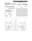
[0006]FIG. 1 schematically illustrates a double flow steam turbine according to one embodiment of the invention.
DETAILED DESCRIPTION OF THE INVENTION
[0007]Referring to FIG. 1, a double, or opposed, flow steam turbine 2 comprises nozzles, or diaphragms, 18 at sections of the turbine 2. As shown in FIG. 1, steam 4 is provided to both nozzles 18 of the double flow steam turbine 2. It should be appreciated that the following description of the flow of the steam 4 applies equally to both nozzles 18 of the double flow steam turbine 2.
[0008]Referring again to FIG. 1, the steam 4 enters the nozzle 18 of each pressure section. Each nozzle 18 is defined by a nozzle outer ring 14 which is supported by an inner ring, or web, 22. The inner ring 22 is supported by a central annulus, or tub 8 that is static relative to a rotor wheel 6 of the double flow steam turbine 2. The steam 4 passes a bucket 12 that is supported by a rotor wheel dovetail projection 10. A portion 26 of the steam 4 is reversed to flow from the aft to the forward side of the first stage turbine wheel and then proceeds to an annular space 16 between the rotor wheel 6 and the tub 8. The reverse steam flow portion 26 may be provided by, for example, steam balance holes 28 either through the bucket 12 and/or the rotor wheel dovetail projections 10.
[0009]In steam turbines, it is common to design the first stage with negative root reaction to provide cooling steam for the first wheel.
[0010]In the double flow steam turbine 2, it is possible to have both turbine ends designed with negative root reaction, and some of the reverse steam flow portion 26 will be trapped in the annular space 16 in the region of the tub 8. In order to provide a sufficient driving force to have a cross flow of cooling steam from one end to the other, a pipe 20 is provided through the tub 8. The pipe 20 extends from the annular space 16 to a region of lower pressure to allow stagnant steam to exit the annular space 16. The pressure differential between the annular space 16 and the lower pressure location will force the reverse steam flow portion 26 to flow through the pipe 20 as shown by arrow 24 to avoid windage heating.
[0011]The double flow steam turbine may be a double flow non-condensing turbine, for example, as used in a desalination process. It should be appreciated, however, that the invention may be used in any double flow steam turbine that requires tub region cooling.
[0012]While the invention has been described in connection with what is presently considered to be the most practical and preferred embodiment, it is to be understood that the invention is not to be limited to the disclosed embodiment, but on the contrary, is intended to cover various modifications and equivalent arrangements included within the spirit and scope of the appended claims.
User Contributions:
comments("1"); ?> comment_form("1"); ?>Inventors list |
Agents list |
Assignees list |
List by place |
Classification tree browser |
Top 100 Inventors |
Top 100 Agents |
Top 100 Assignees |
Usenet FAQ Index |
Documents |
Other FAQs |
User Contributions:
Comment about this patent or add new information about this topic:
Images included with this patent application:
 |  |
| Similar patent applications: | |
| Date | Title |
|---|---|
| 2011-07-07 | Method and apparatus for double flow turbine first stage cooling |
| 2010-09-30 | Method and apparatus for turbine interstage seal ring |
| 2010-07-15 | Steam turbine and cooling method thereof |
| 2011-10-06 | Abradable turbine air seal |
| 2011-10-20 | Gas turbine having cooling insert |
| New patent applications in this class: | |
| Date | Title |
|---|---|
| 2022-05-05 | Fabricated cmc nozzle assemblies for gas turbine engines |
| 2019-05-16 | Ogv electroformed heat exchangers |
| 2018-01-25 | Intermediate case for an aircraft turbomachine made from a single casting with a lubricant duct |
| 2018-01-25 | Turbine vane with coupon having corrugated surface(s) |
| 2018-01-25 | Blade with internal rib having corrugated surface(s) |
| New patent applications from these inventors: | |
| Date | Title |
|---|---|
| 2010-07-15 | Steam turbine having exhaust enthalpic condition control and related method |
| 2010-07-15 | Method and apparatus for varying flow source to aid in windage heating issue at fsnl |
| 2010-06-24 | Opposed flow high pressure-low pressure steam turbine |
| 2009-10-15 | Low exhaust loss turbine and method of minimizing exhaust losses |
| Top Inventors for class "Rotary kinetic fluid motors or pumps" | |
| Rank | Inventor's name |
|---|---|
| 1 | Gabriel L. Suciu |
| 2 | Frederick M. Schwarz |
| 3 | United Technologies Corporation |
| 4 | Brian D. Merry |
| 5 | Craig M. Beers |