Patent application title: AUTOMATED LIQUID CRYSTAL ANALYSIS INSTRUMENT
Inventors:
Michael Wand (Boulder, CO, US)
IPC8 Class: AG01N2760FI
USPC Class:
324453
Class name: Electricity: measuring and testing a material property using electrostatic phenomenon in a liquid
Publication date: 2009-11-19
Patent application number: 20090284262
Inventors list |
Agents list |
Assignees list |
List by place |
Classification tree browser |
Top 100 Inventors |
Top 100 Agents |
Top 100 Assignees |
Usenet FAQ Index |
Documents |
Other FAQs |
Patent application title: AUTOMATED LIQUID CRYSTAL ANALYSIS INSTRUMENT
Inventors:
Michael WAND
Agents:
GREENLEE WINNER AND SULLIVAN P C
Assignees:
Origin: BOULDER, CO US
IPC8 Class: AG01N2760FI
USPC Class:
324453
Patent application number: 20090284262
Abstract:
Provided is a method for measuring one or more properties of liquid
crystals in an automated manner. Also provided is a liquid crystal
analysis instrument (LCAS) that automatically measures one or more
properties of liquid crystals.Claims:
1. A method for measuring physical properties of liquid crystals
comprising:(a) providing a liquid crystal sample;(b) applying one or more
of (1) a voltage to the sample; (2) a temperature to the sample;(c)
measuring one or more physical properties of the liquid crystal
sample;(d) generating a desired result; and(e) displaying the desired
result.
2. The method of claim 1, wherein the physical properties are one or more of: capacitance, resistance, thickness, Threshold voltage, Parallel dielectric constant, Perpendicular dielectric constant, Dielectric anisotropy, Splay elastic constant (K11), Twist elastic constant (K2), Bend elastic constant (K33), VHR (voltage holding ratio), Residual DC voltage, Polarization, Viscosity, Electrical Rise time, Optical Rise time, Bistability, Specific Resistivity, critical pulse width, ion density and Dielectric Constant.
3. The method of claim 1, wherein the voltage is a voltage waveform.
4. The method of claim 1, wherein the temperature is a temperature program.
5. The method of claim 1, wherein a physical property is the capacitance of the liquid crystal sample, and a temperature program is applied to the sample.
6. The method of claim 5, wherein the capacitance of the liquid crystal sample is measured as a heating or cooling temperature program is applied to the sample, generating capacitance v. temperature data, and wherein the desired result is the temperature at which a first or second derivative of the capacitance v. temperature data occurs.
7. The method of claim 6, wherein the desired result is a phase transition temperature.
8. The method of claim 1, wherein the measuring step is performed more than once and statistical analysis is used to generate the result.
9. A LC instrument for measuring physical properties of liquid crystals comprising:a controller;a voltage source in electrical connection with the controller;a waveform generator in electrical connection with the voltage source;a temperature source in electrical connection with the controller;a temperature program generator in electrical connection with the temperature source;an LC cell in electrical connection with the voltage and temperature source;a software program;a display device.
10. The LC instrument of claim 9, wherein the software program includes statistical analysis.
Description:
CROSS-REFERENCE TO RELATED APPLICATIONS
[0001]This application claims priority to U.S. provisional application Ser. Nos. 60/863,761 and 60/863,765, both filed on Oct. 31, 2006, which are hereby incorporated by reference to the extent not inconsistent with the disclosure herein.
BACKGROUND OF THE INVENTION
[0002]There is a need in the art for an instrument which analyzes liquid crystal components. Many instruments populate the liquid crystal (LC) analysis market that measure one or several properties of LCs but there are only a few that claim to measure many properties, both electrical and optical, of liquid crystals. Some LC analysis instruments are made by Toyo, Japan, and Instec, USA.
SUMMARY OF THE INVENTION
[0003]Provided is a method for measuring one or more properties of liquid crystals in an automated manner. Also provided is a liquid crystal analysis instrument (LCAS) that automatically measures one or more properties of liquid crystals.
[0004]More specifically, provided is a method for measuring various properties of liquid crystals comprising: (a) providing a liquid crystal sample; (b) applying one or more of (1) a voltage to the sample; (2) a temperature to the sample; (c) measuring one or more properties of the liquid crystal sample; (d) generating a desired result; and (e) displaying the desired result. The method may optionally include calculating one or more desired values using the measured properties. The voltage may be in the form of a voltage waveform, where the voltage is varied according to a predetermined pattern. The temperature may be in the form of a temperature program, where the temperature is adjusted over time.
BRIEF DESCRIPTION OF THE FIGURES
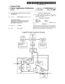
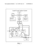
[0005]FIG. 1 shows a generalized block diagram of an exemplary LCAS instrument in its most fundamental form. Different amplifiers, A/D converters, and variations in software provide a wide range of useful analysis instruments.
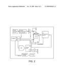
[0006]FIG. 2 shows the electronic nature of the LCAS, which shows an example of the electrical flow necessary to accomplish proper measurement of the LC cell.
DETAILED DESCRIPTION OF THE INVENTION
[0007]Provided in one embodiment is an instrument and method for analysis of data associated with liquid crystal components and mixtures. The instrument and methods can be combined in different ways, as further described here.
[0008]In one embodiment, one or more of the following features are provided by the Liquid Crystal Analysis System (LCAS):
1. Auto-Calibration
[0009]The system provides auto-calibration against, for example, a known NIST standard. In one embodiment, a commercial surface-mount resistor and capacitor were used and attached to a PCB board for easy connection to the custom cell holder, but any known and verified standard may be used.
2. Statistical Analysis
[0010]The system provides auto-statistical analysis of the LC being tested. This feature can be set up to run multiple times, from 2 to 1000, more preferably 10 to 20 times. A table of results is generated, in one embodiment. The statistical analysis can be applied to any desired parameter, such as those described here. In one embodiment, one or more of the following parameters are provided:
TABLE-US-00001 Parameter Mean St. Dev. Variance Min. Max. Range Viscosity Dielectric Constant Resistivity Electrical Rise Time Polarization Number of counts
[0011]All statistical data is calculated using standard equations, for example:
Mean = P m n ##EQU00001## Variance = ( P m - Mean ) 2 n - 1 ##EQU00001.2## StdDeviation= {square root over (Variance)}
Range=Max-Min
Where,
[0012]Pm=value of parameter measured in each testn=number of testsMax=maximum value of the parameter for all testsMin=minimum value of the parameter for all tests
[0013]Multiple measurements can be made on a given sample to provide the desired statistical significance, or for other reasons. In one embodiment, from 10-20 measurements are used for the statistics. In one embodiment, from 5-1000 measurements are used for the statistics. Other numbers of measurements can be made, as known in the art, to balance time of measurement with statistical significance of the data.
[0014]Results can be displayed in many formats, including either jpg (picture) format or els (graphic) format, or ASCI (.doc) format, read by any word processor. Other formats are possible, as known in the art.
3. Phase Diagram
[0015]The property vs. temperature profile can be used to determine the LC phase diagram of an LC. The most common way to accomplish this is by measuring the heat of enthalpy, or the release or absorption of heat when the sample is cooled or heated, for instance, from its melting point to its clearing point. The method described here requires many fewer sensors and less insulation to accomplish a similar task. By measuring the change in capacitance upon heating or cooling, it is possible to obtain an accurate phase diagram of the LC. Visually examining (or using mathematical analysis) of the resulting curve will provide in a determination of the LC transitions. One embodiment of this method involves locating the area on the curve that most quickly changes, using for example, the first derivative, and more beneficially, the second derivative of the curve and electronically noting the temperature at which this took place. The values are then recorded and reported as an LC transition point, after adjustment with a constant, if necessary. Examples of these transitions are melting point, freezing point, smectic A to nematic, nematic to isotropic, crystal to nematic, smectic C to nematic, smectic C to isotropic, and others.
[0016]In one embodiment, one or more of the following parameters are measured or calculated by the LCAS: [0017]Capacitance [0018]Resistance [0019]Thickness [0020]Threshold voltage [0021]Parallel dielectric constant [0022]Perpendicular dielectric constant [0023]Dielectric anisotropy [0024]Splay elastic constant, K11 [0025]Twist elastic constant, K2 [0026]Rotational viscosity [0027]Bend elastic constant, K33 [0028]VHR (voltage holding ratio) [0029]Residual DC voltage [0030]Polarization [0031]Viscosity [0032]Electrical Rise time [0033]Optical Rise time (0-10%, 0-90%, 10-90%) [0034]Bistability [0035]Specific Resistivity [0036]Dielectric Constant [0037]Critical pulse width [0038]Ion density
[0039]In particular embodiments, any or all of these parameters, including all possible combinations of any or all of these parameters are automatically calculated by the LCAS. The LC properties described here are known in the art.
[0040]The following describes one embodiment of using the device and methods. The cell is filled and temperature prepared using standard procedures known in the art. A ferroelectric LC must be filled in the cell when the LC is in the isotropic phase. A nematic LC can be filled in the cell at room temperature. The parasitic capacitance and resistance of the instrument are measured, if needed. The cell's thickness, resistance and capacitance, along with other values if necessary if desired are measured. The test cell's resistance and capacitance are measured ("nulling").
[0041]The desired voltage drive waveform frequency and amplitude are selected and applied to the cell, and the desired parameters are measured. The desired temperature profile is selected, and temperature profile is applied to the cell. The desired parameters involving temperature are then measured. Results are calculated using the equations described herein. The data provided by the measurements can be used for perform other measurements. For example, the spontaneous polarization of a single polarization peak can be measured by viewing the polarization peak on a monitor, and using an algorithm to measure the spontaneous polarization. Optical measurements can be made using optical instruments known in the art.
[0042]The connections between the cell, temperature source, voltage source and display, as well as other components can be any methods well known in the art. Adjusting the voltage applied, the temperature applied, and other parameters can be done using methods well known in the art. Unless otherwise specified, the units of measurement are usual in the art.
[0043]The following are some exemplary equations used to calculate various parameters described here.
Spontaneous Polarization:
[0044]The spontaneous polarization (Ps) is calculated as
Ps = 1 A c ∫ o T 2 i p ( t ) t ##EQU00002##
where,Ps=spontaneous polarizationAc=area of the liquid crystalT=period of test waveformIp(t)=polarization currentPs is expressed in
nanoColumbs centimeter 2 ##EQU00003##
Electrical Rise Time
[0045]The electrical rise time is measured from the start of the rising edge of the drive waveform to the peak response of the polarization current. The rise time is expressed in microseconds. The electrical rise time correspondencs approximately to the 0% to 50% optical rise time. The more commonly cited 10% to 90% optical rise time will be approximately 2/3 of the electrical rise time.
Applied Electric Field
[0046]The electric field is calculated as
E = V P d ##EQU00004##
where,E=applied electric fieldVP=peak voltage of drive waveformd=cell thickness
[0047]The units of the applied electric field are volts per micrometer.
Specific Resistivity
[0048]The formula used for calculating the specific resistivity is
p = R M A C d ##EQU00005##
wherep=specific resistivityRM=measured resistanceAC=area of the liquid crystald=cell thickness
[0049]The specific resistivity is expressed in ohms centimeter.
Dielectric Constant
[0050]The dielectric constant is determined from the ratio of the measured capacitances by
= C M - C P C EMPTY - C P ##EQU00006##
whereε=dielectric constantCM=measured capacitance of the filled test cellCEMPTY=measured capacitance of the empty cellCP=measured parasitic capacitance
[0051]The dielectric constant has no units.
[0052]Since non-linear contributions to the dielectric are nulled by the bridge, only the linear dielectric constant is measured and reported. This value is relatively frequency-independent and should be comparable to the unnulled capacitance at high frequencies (>25 KHz). For nematic LCs, the dielectric anisotropy is measured by the single cell method of Wu. For Ferroelectric LCs, the dielectric anisotropy can be obtained by measurement with a parallel-aligned cell. The dielectric constants of the two cells can be used to calculate the dielectric anisotropy.
Ferroelectric Liquid Crystal Rotational Viscosity
[0053]The rotational viscosity is found using the following equation
η = A C P S 2 V P d I P ##EQU00007##
whereη=rotational viscosityAC=area of the liquid crystalPS=spontaneous polarizationVP=drive voltage at IP d=cell thicknessIP=measured peak current
[0054]Viscosity is expressed in milli-Pascal*second.
[0055]This measurement is particularly sensitive to the quality of the alignment. Certain geometries, such as quasi-bookshelf, are known to give higher viscosity.
Specific Resistivity
[0056]The specific resistivity is found using the following formula
p = A C R M R P ( R M - R P ) d ##EQU00008##
wherep=specific resistivityAC=area of the liquid crystalRM=measured test cell resistanceRP=measured parasitic resistanced=cell thickness
[0057]The specific resistivity is expressed in ohm*centimeter.
Threshold Voltage
[0058]The threshold voltage is a measured quantity. It is measured at a user specified percentage above the lower inflection point of the capacitance verses voltage curve. The default percentage is 5%.
Parallel Dielectric Constant
[0059]The parallel dielectric constant is determined as
PAR = C PAR C EMPTY ##EQU00009##
whereεPAR=parallel dielectric constantCPAR=capacitance at Vth/Vrms=0 as extrapolated from a normalized threshold voltage versus cell capacitance plot.CEMPTY=measured empty cell capacitance
[0060]The parallel dielectric constant has no units.
Perpendicular Dielectric Constant
[0061]The perpendicular dielectric constant is determined as
PERP = C PERP C EMPTY ##EQU00010##
whereεPERP=perpendicular dielectric constantCPERP=measured capacitance at V<<Vth CEMPTY=measured empty cell capacitance
[0062]The perpendicular dielectric constant has no units.
Dielectric Delta
[0063]The dielectric delta is the difference between the parallel and perpendicular dielectric constants as given by
Δε=εPAR-εPERP
[0064]Δε=dielectric deltaεPAR=parallel dielectric constantεPERP=perpendicular dielectric constant
K11
[0065]The splay elastic constant (K11) is determined using the equation
K 11 = ( V th π ) 2 0 Δ 3 ##EQU00011##
whereK11=splay elastic constantVth=threshold voltageε0=dielectric constant=8.85e-12 Farads/meterΔε=dielectric delta
K22
[0066]The twist elastic constant (K22) is estimated as 0.6*K11.
K33
[0067]The bend elastic constant (K33) is obtained from curve fitting algorithm of the CV curve.
K33/K11
[0068]The ratio of the bend to splay constant is found as K33/K11.
Rotational Viscosity
[0069]The nematic rotational viscosity is calculated using the following equation
η = A C ( 0 Δ ) 2 2 I P ( V P d ) 3 ##EQU00012##
whereη=rotational viscosityAC=area of the liquid crystalε0=dielectric constant=8.85e-12 Farads/meterΔε=dielectric deltaIP=measured peak currentVP=drive voltage at IP d=cell thickness
[0070]Viscosity is expressed in milli-Pascal*second.
[0071]This calculation is based on the high voltage limit as described in Jpn. J. Appl. Phys. 33. L119 (1994).
Ion Density
[0072]The ion density is calculated as
ionDensity = q e A C d ##EQU00013##
whereionDensity=positive or negative ion densityq=measured chargee=electron charge=1.6022e-19 CoulombsAC=cell aread=cell thickness
Example Instrument
[0073]The methods described can be used with any suitable instrument, as known in the art. The following description provides one embodiment of a suitable instrument.
[0074]In one embodiment, provided is an Automated Liquid Crystal Analysis System (LCAS) instrument, which is a fully automated system in one embodiment, consisting of hardware and software, for measuring the physical parameters of liquid crystal materials, of which nematic and ferroelectric are examples. In one embodiment, the hardware portion of the system consists of a Windows based computer, a PCI parallel interface card, and an electronic instrument that comprises, and in one embodiment, comprises the following: a waveform generator used to drive the LC cell, a bridge to measure the capacitive and resistive currents through the LC cell, and an integrator to measure total polarization charge after capacitive, resistive, and noise currents have been suppressed. The above may be housed in different enclosures, with the more preferable option being one enclosure. All aspects of the hardware are under software control and accessible to the user. The software portion of the system comprises, and in one embodiment, consists of, an on-screen menu bar to facilitate user interaction, the driver routines which interpret the user's key presses and send the appropriate control signals to the hardware, and an on-screen oscilloscope display to monitor the real-time input and output of the LC cell while measuring the resistance and capacitance of the LC cell.
[0075]In one embodiment, provided as a part of the LCAS is an automated dielectric spectrometer which measures the properties of a dielectric medium by first providing an electrical stimulus, and then reading back the signal, either capacitive, or optically. In one embodiment, the instrument can be connected to a host computer using only one cable. In one embodiment, the instrument is connected to a host computer using a PCI connection. In one embodiment, the instrument is connected to a host computer using a USB connection. In one embodiment, the instrument measures both optical and electrical signals. In one embodiment, the instrument contains software that allows convenient interface with existing software, such as Lab View, or a spreadsheet or word processing program. In one embodiment, the software is graphically based. In one embodiment, one or more of Electrical Rise time, Optical Rise time, Bistability, Specific Resistivity, Dielectric Constant are measured. In one embodiment, one or more of Splay elastic constant, Bend elastic constant, Dielectric anisotropy, Perpendicular dielectric constant, Parallel dielectric constant, Threshold voltage, VHR, residual DC voltage are measured. Other parameters may be measured. In one embodiment, there is an analog dial that adjusts the voltage applied to the cell. In one embodiment, there is a safety feature preventing shock by automatically shutting down the system when more than a specified current is detected, for example, >50 milliamps. In one embodiment, the instrument uses an arbitrary waveform generator to provide slow (0.001 Hz-30 KHz) triangle wave, either balanced or DC offset. In one embodiment, the waveform is one or more of the following: square wave, triangle wave, offset triangle wave, DC level, sine wave, dual pulse wave, and any symmetrical arbitrary wave. The frequency range is from 0.001-30 Hz in one embodiment, and the voltage output is up to 120 Vp in one embodiment. In one embodiment, the instrument uses an ultra-low noise voltage amplifier to measure the very high resistivity. In one embodiment, the instrument uses a three or four wire cell clip, allowing for minimization of noise. In one embodiment, the instrument automatically calculates the statistics of the LC cell. In one embodiment, the instrument automatically calibrates the system based on a known standard. In one embodiment, the output is captured as jpg or tab delimited data such as Excel format. In one embodiment, the LC properties can be optionally scanned vs. temperature affording the appropriate data, which can be presented as graphs. This feature can be implemented with the provide VHR coolNhot box, a hot stage with a range of -20 to +120° C., for example. The LCAS can also be interfaced with any commercial hot stage, for example, Instecc, Mettler, Linkam and others, where the temperature range can be as broad as -196 to +350° C.
[0076]In one embodiment, the system is controlled using a graphical user interface. In one embodiment, the applied drive signal is displayed, and the real time current or voltage response of the test cell to the applied signal is displayed. In one embodiment, the amplitude, frequency and applied waveform type can be selected using the graphical user interface.
[0077]In additional embodiments, a voltage holding ratio (VHR) coolNhot box is described for measurement of the voltage holding ratio and residual DC of the nematic LC cell using a voltage-based amplifier. This box is integrated into a Peltier stage allowing all properties to be measured in this enclosure from about -20 C to about +120° C., for example. The box can be either cooled by air with a fan, or if lower noise level is desired, a liquid cooling system can be used. In one embodiment, it is desired that the box is an enclosed system that does not require the use of an external water supply.
[0078]In the case of the nematic LC, for example, a C vs. V curve is automatically measured and the primary nematic properties are then calculated from this information, using the methods and techniques described herein.
REFERENCES
[0079]1. Patel, et al., Chem. Phys. Lett. 137, 91 (1987). [0080]2. Dahl, et al. Phys. Rev. A 36, 4380 (1987). [0081]3. Gouda et al., J. Appl. Phys. 67, 180 (1990). [0082]4. Escher, et al. Liquid Crystals 3, 467 (1988). [0083]5. Wu et al., Liquid Crystals 10, 635-646 (1991). [0084]6. Imai et al. Jpn. J. Appl. Phys. 33, L119 (1994).
[0085]One of ordinary skill in the art will appreciate that methods, device elements and parameters other than those specifically exemplified can be employed in the practice of the invention without resort to undue experimentation. All art-known functional equivalents, of any such methods, device elements, and parameters are intended to be included in this invention. Whenever a range is given in the specification, for example, a temperature range, a time range, or a voltage range, all intermediate ranges and subranges, as well as all individual values included in the ranges given are intended to be included in the disclosure.
[0086]As used herein, "comprising" is synonymous with "including," "containing," or "characterized by," and is inclusive or open-ended and does not exclude additional, unrecited elements or method steps. As used herein, "consisting of" excludes any element, step, or ingredient not specified in the claim element. As used herein, "consisting essentially of" does not exclude materials or steps that do not materially affect the basic and novel characteristics of the claim. Any recitation herein of the term "comprising", particularly in a description of components of a composition or in a description of elements of a device, is understood to encompass those compositions and methods consisting essentially of and consisting of the recited components or elements. The invention illustratively described herein suitably may be practiced in the absence of any element or elements, limitation or limitations which is not specifically disclosed herein. The invention may also be practiced with the inclusion of components that are known in the art, such as electrical components that are not specifically mentioned here.
[0087]The terms and expressions which have been employed are used as terms of description and not of limitation, and there is no intention in the use of such terms and expressions of excluding any equivalents of the features shown and described or portions thereof, but it is recognized that various modifications are possible within the scope of the invention claimed. Thus, it should be understood that although the present invention has been specifically disclosed by preferred embodiments and optional features, modification and variation of the concepts herein disclosed may be resorted to by those skilled in the art, and that such modifications and variations are considered to be within the scope of this invention. All references are incorporated by reference to the extent not inconsistent with the disclosure herewith.
[0088]In general the terms and phrases used herein have their art-recognized meaning, which can be found by reference to standard texts, journal references and contexts known to those skilled in the art.
[0089]Although the description herein contains many specificities, these should not be construed as limiting the scope of the invention, but as merely providing illustrations of some of the embodiments of the invention. Thus, additional embodiments are within the scope of the invention.
User Contributions:
comments("1"); ?> comment_form("1"); ?>Inventors list |
Agents list |
Assignees list |
List by place |
Classification tree browser |
Top 100 Inventors |
Top 100 Agents |
Top 100 Assignees |
Usenet FAQ Index |
Documents |
Other FAQs |
User Contributions:
Comment about this patent or add new information about this topic:
| People who visited this patent also read: | |
| Patent application number | Title |
|---|---|
| 20140174683 | PROCESS FOR THE PRODUCTION OF PAPER |
| 20140174682 | COMPOSITION AND USE OF HYDROGENATED ALKYL KETENE DIMERS |
| 20140174681 | FIRE RETARDANT TREATED FLUFF PULP WEB AND PROCESS FOR MAKING SAME |
| 20140174680 | PULPING PROCESSES |
| 20140174679 | BCTMP Filtrate Recycling System and Method |
Images included with this patent application:
 |  |
 |  |
 |  |
| Similar patent applications: | |
| Date | Title |
|---|---|
| 2010-06-03 | Liquid crystal display panel and its inspecting method |
| 2012-07-19 | Subsurface electromagnetic survey technique using expendable conductivity, temperature, and depth measurement devices |
| 2009-11-26 | Process condition evaluation method for liquid crystal display module |
| 2010-10-21 | Control liquid identifying method and analysis device |
| 2012-05-03 | Automated emergency power supply test using engine exhaust temperature |
| New patent applications in this class: | |
| Date | Title |
|---|---|
| 2010-12-23 | System and method for determining the performance of a wearable electrode |
| New patent applications from these inventors: | |
| Date | Title |
|---|---|
| 2016-06-09 | Birefringence improving agent, ferroelectric liquid crystal composition and liquid crystal display device using the agent, and compound |
| 2014-12-11 | Polymer-doped vertically-aligned nematic liquid crystals |
| 2012-12-27 | Liquid crystals having cyclohexyl core structures and fluorinated tails |
| 2012-05-03 | Polymer-doped vertically-aligned nematic liquid crystals |
| 2010-09-02 | Ferroelectric liquid crystal (flc) polymers |
| Top Inventors for class "Electricity: measuring and testing" | |
| Rank | Inventor's name |
|---|---|
| 1 | Udo Ausserlechner |
| 2 | David Grodzki |
| 3 | Stephan Biber |
| 4 | William P. Taylor |
| 5 | Markus Vester |