Patent application title: Heat dissipating structure
Inventors:
Ching Hang Chen (Sinjhuang City, TW)
Assignees:
ASIA VITAL COMPONENTS CO., LTD.
IPC8 Class: AH05K720FI
USPC Class:
361695
Class name: Air with air circulating means fan or blower
Publication date: 2009-11-12
Patent application number: 20090279254
Inventors list |
Agents list |
Assignees list |
List by place |
Classification tree browser |
Top 100 Inventors |
Top 100 Agents |
Top 100 Assignees |
Usenet FAQ Index |
Documents |
Other FAQs |
Patent application title: Heat dissipating structure
Inventors:
Ching Hang Chen
Agents:
NIKOLAI & MERSEREAU, P.A.
Assignees:
Asia Vital Components Co., Ltd.
Origin: MINNEAPOLIS, MN US
IPC8 Class: AH05K720FI
USPC Class:
361695
Patent application number: 20090279254
Abstract:
A heat dissipating structure with a casing and at least a power-free
heat-dissipating device therein is provided. The power-free
heat-dissipating device is driven by an air stream outside and inside the
casing to rotate. The rotating power-free heat-dissipating device
introduces the air stream into the casing and expels the air stream from
the casing so as to facilitate circulation favorable for heat
dissipation, thereby enhancing heat dissipation, enabling power-free
operation, and serving a power-saving purpose.Claims:
1. A heat dissipating structure, comprising:a casing with a first hole and
a second hole; andat least a power-free heat-dissipating device disposed
at and corresponding in position to one of the first hole and the second
hole, allowing an air stream one of inside and outside the casing to be
one of expelled from and introduced into the casing by the power-free
heat-dissipating device, so as to drive the power-free heat-dissipating
device to rotate, and enable the air stream one of inside and outside the
casing to be one of expelled from and introduced into the casing via one
of the first hole and the second hole.
2. The heat dissipating structure of claim 1, wherein the power-free heat-dissipating device further comprises:a rotating portion shaped like a hollow drum, comprising a plurality of strips, and formed with a receptive opening below, the strips being circumferentially disposed, equidistantly spaced, and partially open;a bladed fan disposed in the rotating portion and near the opening of the rotating portion, comprising a plurality of blades, and centrally formed with an aperture; anda fixing portion with an end extendingly formed with an axle penetratably disposed in the aperture of the bladed fan so as to be pivotally coupled to the rotating portion.
3. The heat dissipating structure of claim 1, wherein the power-free heat-dissipating device is optionally provided with a conversion unit driven by the power-free heat-dissipating device to perform energy conversion for self-contained power generation.
4. The heat dissipating structure of claim 2, wherein the power-free heat-dissipating device is optionally provided with a conversion unit driven by the power-free heat-dissipating device to perform energy conversion for self-contained power generation.
5. The heat dissipating structure of claim 1, wherein the power-free heat-dissipating device is provided with a hood thereon.
6. The heat dissipating structure of claim 2, wherein the power-free heat-dissipating device is provided with a hood thereon.
7. The heat dissipating structure of claim 1, wherein the first hole is formed on an upper side of the casing and the second hole on a rear side of the casing.
Description:
BACKGROUND OF THE INVENTION
[0001]1. Field of the Invention
[0002]The present invention relates to heat dissipating structures, and more particularly, to a heat dissipating structure for use with an electronic equipment casing.
[0003]2. Description of the Prior Art
[0004]A variety of electronic equipment nowadays, host computers in particular, are internally installed with various peripherals capable of high-speed computation, such as CPU, interface cards, high-capacity memory units (hard disk drives), DVD, CD/DVD-R/RW drives, power supplies, etc. Inside an airtight casing of a host computer, peripherals and electronic components in operation generate heat of different temperatures. The CPU performs computation at high speed and thereby is the largest heat-generating component inside the host computer. A problem that calls for immediate solution involves efficient elimination of heat generated from within a host computer, an operating CPU especially. Manufacturers usually install additional heat-dissipating devices in the host computers or electronic apparatus/equipment such that the heat-dissipating devices reduce ambient temperature or temperature of components inside the host computers or electronic apparatus/equipment.
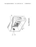
[0005]Referring to FIG. 1, which is a perspective view of the prior art, a computer casing 1 taught by the prior art is installed with a motherboard 2 therein. The computer casing 1 has a rear side formed with a venting hole 11. The motherboard 2 is installed with a heat-generating source 21 thereon. The heat-generating source 21 is installed with a cooling fan 22 thereon. The cooling fan 22 in operation moves an air stream to cool down the heat-generating source 21 and dissipate heat therefrom. After having been moved by the cooling fan 22 to cool down the heat-generating source 21, the air stream lingers in the vicinity of the heat-generating source 21 and stays so far from the venting hole 11 that it is necessary to additionally install a ventilation fan 13 at the venting hole 11 so as to vent heat out of the computer casing 1.
[0006]According to the prior art, not only is heat generated by peripherals and electronic components installed in a host computer confined to the casing of the host computer, but a plurality of heat sources present inside the casing of the host computer generate heat concurrently, and thus heat is accumulated inside the casing in the same way as the mechanism for greenhouse effect. Hence, it is necessary to additionally install a ventilation fan to facilitate convection between air streams otherwise shut inside the casing and air streams outside the casing. However, the extra ventilation fan always consumes extra power otherwise available to the computer, and thus voltage of the internal power supply system of the computer is rendered unstable. Accordingly, the prior art has the following drawbacks: [0007]1. inefficient heat dissipation, [0008]2. power-consuming, and [0009]3. inefficient convection between air streams inside a casing and air streams outside the casing.
SUMMARY OF THE INVENTION
[0010]It is a primary objective of the present invention to provide on a casing at least a heat-dissipating device capable of self-contained operation and capable of removing heat from the casing so as to be power-saving and heat-dissipating.
[0011]The present invention provides a heat dissipating structure. The heat dissipating structure includes a casing and at least a power-free heat-dissipating device disposed on the casing. An air stream outside the casing drives the power-free heat-dissipating device to rotate. The rotating power-free heat-dissipating device introduces the air stream into the casing so as to facilitate circulation favorable for heat dissipation, thereby enhancing heat dissipation, enabling power-free operation, and serving a power-saving purpose. Hence, the present invention has the following advantages: [0012]1. power-saving, [0013]2. efficient heat dissipation, and [0014]3. efficient convection between air streams inside a casing and air streams outside the casing.
BRIEF DESCRIPTION OF THE DRAWINGS
[0015]FIG. 1 (PRIOR ART) is a perspective view of the prior art;
[0016]FIG. 2 is an exploded view of a preferred embodiment of the present invention;
[0017]FIG. 3 is a perspective view of the preferred embodiment of the present invention;
[0018]FIG. 4 is a schematic view of the preferred embodiment of the present invention;
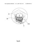
[0019]FIG. 4A is an enlarged view showing a power-free heat-dissipating device of the preferred embodiment of the present invention;
[0020]FIG. 5 is a schematic view of another preferred embodiment of the present invention;
[0021]FIG. 5A is an enlarged view showing a power-free heat-dissipating device of the other preferred embodiment of the present invention; and
[0022]FIG. 6 is an exploded view showing the power-free heat-dissipating device of the other preferred embodiment of the present invention.
DETAILED DESCRIPTION OF THE EMBODIMENTS
[0023]The present invention is herein illustrated with preferred embodiments and drawings, so that one skilled in the pertinent art can easily understand the technical means and structures employed to achieve the aforesaid objective, other advantages and effects of the present invention from the disclosure of the invention.
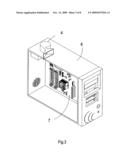
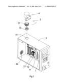
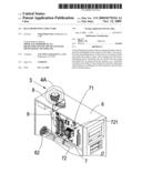
[0024]Referring to FIGS. 2, 3, 4, 4A, 5, 5A and 6, an electronic equipment casing 6 is provided with at least a power-free heat-dissipating device 3 thereon and a hood 4 for protecting the power-free heat-dissipating device 3. An air stream 8 outside the electronic equipment casing 6 drives the power-free heat-dissipating device 3 to rotate. Owing to the rotation of the power-free heat-dissipating device 3, the cool air stream 8 outside the electronic equipment casing 6 is introduced into the electronic equipment casing 6 to circulate therein, so as to effectuate heat dissipation and save power. With the power-free heat-dissipating device of the present invention, drawbacks of the prior art, namely excessive power consumption and inefficient removal of heat from the casing, are resolved.
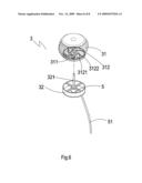
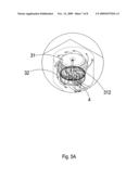
[0025]The power-free heat-dissipating device 3 comprises a rotating portion 31 and a fixing portion 32. The rotating portion 31 is shaped like a hollow drum and comprises a plurality of strips circumferentially disposed, equidistantly spaced, and partially open. The rotating portion 31 is formed with a receptive opening 311 below. A bladed fan 312 is disposed in the rotating portion 31 and near the opening 311 of the rotating portion 31. The bladed fan 312 comprises a plurality of blades 3121 and is centrally formed with an aperture 3122. The fixing portion 32 has an end extendingly formed with an axle 321 penetratably disposed in the aperture 3122 of the bladed fan 312 so as to be pivotally coupled to the rotating portion 31.
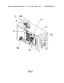
[0026]The electronic equipment casing 6 has an upper side and a rear side. The upper side of the electronic equipment casing 6 is formed with a first vent 61 corresponding in position to the power-free heat-dissipating device 3. The rear side of the electronic equipment casing 6 is formed with at least a second vent 62. The second vent 62 exhausts air streams otherwise held inside the electronic equipment casing 6. A motherboard 7 is received inside the electronic equipment casing 6. The motherboard 7 is disposed with a heat-generating source 71 thereon. A heat-dissipating module 72 with a fan 721 is disposed on the heat-generating source 71.
[0027]Heat generated by the heat-generating source 71 is dissipated by means of air streams produced as a result of rotation of the fan 721 of the heat-dissipating module 72 disposed over the heat-generating source 71; meanwhile, two routes of circulation favorable for heat dissipation are available. The first route involves collecting the cool air stream 8 outside the hood 4 by means of the hood 4, driving the rotating portion 31 of the power-free heat-dissipating device 3 to rotate by means of the air stream 8, and introducing the air stream 8 into the electronic equipment casing 6 by means of the rotation of the bladed fan 312 in the rotating portion 31. In so doing, the power-free heat-dissipating device 3 speeds up the flow of a hot air stream 9 inside the electronic equipment casing 6 and the expulsion of the hot air stream 9 from the electronic equipment casing 6 via the second vent 62, so as to engender circulation-based heat dissipation and thereby lower the temperature inside the electronic equipment casing 6. The second route involves driving the rotating portion 31 of the power-free heat-dissipating device 3 to rotate by means of the ascent of the hot air stream 9 generated by the heat-generating source 71 and other electronic components inside the electronic equipment casing 6, and driving the hot air stream 9 out of the electronic equipment casing 6 by means of the rotation of the bladed fan 312 in the rotating portion 31. In so doing, the power-free heat-dissipating device 3 speeds up the flow of the hot air stream 9 inside the electronic equipment casing 6 and the expulsion of the hot air stream 9 from the electronic equipment casing 6 via the second vent 62, so as to engender circulation-based heat dissipation and thereby lower the temperature inside the electronic equipment casing 6.
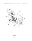
[0028]A conversion unit 5 is optionally disposed on the power-free heat-dissipating device 3, or is disposed on the electronic equipment casing 6 (not shown) in a standalone manner. The power-free heat-dissipating device 3 in operation drives the conversion unit 5 to rotate. Kinetic energy generated by the rotation of the power-free heat-dissipating device 3 is converted into electrical energy by the conversion unit 5. The resultant electrical power is transferred, by a wire 51 connected to the conversion unit 5, to other components for usage or storage. Accordingly, a heat dissipating structure of the present invention generates extra power and supplies the extra power to other components for usage or storage with a view to serving a power-saving purpose, thereby solving a drawback of the prior art, namely excessive power consumption.
[0029]The above-described descriptions of the embodiments are only to illustrate the preferred implementation according to the present invention, and it is not to limit the scope of the present invention. It is apparent to those skilled in the art that all equivalent modifications and variations made in the foregoing embodiments according to the spirit and principle in the disclosure of the present invention should fall within the scope of the appended claims
[0030]In conclusion, the heat dissipating structure of the present invention is capable of accomplishing the effect thereof and achieving the objective thereof, and thus the present invention is novel, non-obvious, and useful, and meets all the conditions for filing an invention patent application. The applicant hereby files the invention patent application in hopes of receiving allowance of the invention patent application and securing patent protection.
User Contributions:
comments("1"); ?> comment_form("1"); ?>Inventors list |
Agents list |
Assignees list |
List by place |
Classification tree browser |
Top 100 Inventors |
Top 100 Agents |
Top 100 Assignees |
Usenet FAQ Index |
Documents |
Other FAQs |
User Contributions:
Comment about this patent or add new information about this topic:
Images included with this patent application:
 |  |
 |  |
 |  |
 |  |
 |
| Similar patent applications: | |
| Date | Title |
|---|---|
| 2009-06-25 | Heat dissipating structure |
| 2009-11-12 | Heat dissipating structure |
| 2010-06-17 | Heat dissipating fan structure of dual motor |
| 2011-05-12 | Electronic device with heat dissipating structure |
| 2009-01-08 | Heat-dissipating casing structure |
| New patent applications in this class: | |
| Date | Title |
|---|---|
| 2016-09-01 | Electronic device having heat radiator and method for controlling the electronic device |
| 2016-07-14 | Display device having fan |
| 2016-06-30 | Suspended electronic display and cooling assembly |
| 2016-06-23 | Method and device for cooling equipment provided with electronic boards, using at least one distinct fluid-cooled cooling board |
| 2016-06-16 | Reversible fan assembly |
| Top Inventors for class "Electricity: electrical systems and devices" | |
| Rank | Inventor's name |
|---|---|
| 1 | Zheng-Heng Sun |
| 2 | Levi A. Campbell |
| 3 | Li-Ping Chen |
| 4 | Robert E. Simons |
| 5 | Richard C. Chu |