Patent application title: Hanging Basket
Inventors:
Robert Chen (Taipei, TW)
IPC8 Class: AA47G704FI
USPC Class:
248318
Class name: Supports suspended supports receptacle or bowl
Publication date: 2009-03-26
Patent application number: 20090078842
Inventors list |
Agents list |
Assignees list |
List by place |
Classification tree browser |
Top 100 Inventors |
Top 100 Agents |
Top 100 Assignees |
Usenet FAQ Index |
Documents |
Other FAQs |
Patent application title: Hanging Basket
Inventors:
Robert Chen
Agents:
Kamrath & Associates, P.A.;Suite 245
Assignees:
Origin: GOLDEN VALLEY, MN US
IPC8 Class: AA47G704FI
USPC Class:
248318
Abstract:
A hanging basket has a basket, multiple suspension lines and multiple
basket connectors. The basket has a sidewall, an edge, a connecting ring
formed around the edge and multiple mounting holes formed around and
through the sidewall of the basket. The basket connectors are connected
respectively to the suspension lines. Each basket connector has a lip
hook and a post, The lip hook and post are formed opposite to each other.
The lip hooks of the basket connectors and the connecting ring of the
basket selectively hook to each other. The posts of the basket connectors
are selectively mounted respectively in the mounting holes. The basket
will not detach from the suspension assembly even though the hanging
basket hangs in high places and sways or bumps other hanging baskets or
objects.Claims:
1. A hanging basket comprisinga basket havinga bottom;a sidewall being
formed around and protruding up from the bottom of the basket and
havingan edge;an outer surface; andmultiple mounting holes being formed
through and around the sidewall near the edge; anda connecting ring being
formed on and protruding out from the edge of the sidewall and havingan
outer edge; anda lip being formed around and protruding down from the
outer edge of the connecting ring and having an outer surface; anda
suspension assembly havingmultiple suspension lines, each suspension line
havingan upper end; anda lower end; andmultiple basket connectors being
resilient and U-shaped, being connected respectively to the lower ends of
the suspension lines and being connected to the connecting ring and
respectively to the mounting holes, and each basket connector havinga
cross member being connected to the lower end of a corresponding one of
the suspension lines and having two ends;two walls being formed
respectively on and protruding down from the ends of the cross member,
and each wall havinga distal edge; andan inner surface;a lip hook being
formed on the distal edge of one wall of the basket connector and bending
parallel to the inner surface of the wall and hooking on the connecting
ring of the basket; anda post being formed on and protruding transversely
from the inner surface of the wall of the basket connector opposite to
the lip hook, being mounted selectively through a corresponding one of
the mounting holes of the sidewall of the basket and abutting the lip
hook.
2. The hanging basket as claimed in claim 1, whereinthe connecting ring of the basket further has multiple indentations being formed in the outer surface of the lip and corresponding respectively to the mounting holes of the sidewall; andthe lip hook of basket connector being mounted selectively in a corresponding one of the indentations of the connecting ring.
3. The hanging basket as claimed in claim 1, whereinthe suspension assembly further has a mounting connector; andthe upper ends of the suspension lines of the suspension assembly are connected to the mounting connector.
4. The hanging basket as claimed in claim 2, whereinthe suspension assembly further has a mounting connector; andthe upper ends of the suspension lines of the suspension assembly are connected to the mounting connector.
Description:
BACKGROUND OF THE INVENTION
[0001]1. Field of the Invention
[0002]The present invention relates to a hanging basket, especially to a hanging basket that has suspension lines hooked securely in the edge of the basket to allow the basket to hang firmly and high.
[0003]2. Description of the Prior Arts
[0004]A hanging basket displays an article like a flowerpot in high places to make good use of vertical space and to decorate the environment.
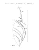
[0005]With reference to FIG. 4, a conventional hanging basket comprises a basket (30) and a suspension assembly (40).
[0006]The basket (30) has an edge, an outer surface and a connecting ring (31). The connecting ring (31) is formed around the edge of the basket (30) at the outer surface.
[0007]The suspension assembly (40) has a mounting connector, multiple suspension lines (41) and multiple basket connectors (42). Each suspension line (41) has an upper end and a lower end. The upper end is connected to the mounting connector. The basket connectors (42) are connected respectively to the lower ends of the suspension lines (41), and each basket connector (42) has a cross member, two walls (421) and two lip hooks (422). The cross member of the basket connector (42) is connected to the lower end of the suspension line (41). The walls (421) of the basket connector (42) protrude transversely from the cross member of the basket connector (42) opposite to each other, and each wall (421) has an edge. The lip hooks (422) are formed respectively on the edges of the walls (421) of the basket connector (42), face each other and may hook the connecting ring (31) of the basket (30) to hang the basket (30) in high places.
[0008]However, the basket (30) is connected to the suspension assembly (40) only with the connecting ring (31) being hooked to the lip hooks (422). The connecting ring (31) and the lip hooks (422) may slide relative to each other or the basket (30) may fall from the suspension assembly (40) and injure people.
[0009]To overcome the shortcomings, the present invention provides a hanging basket to mitigate or obviate the aforementioned problems.
SUMMARY OF THE INVENTION
[0010]The main objective of the present invention is to provide a hanging basket that will hang securely in high places.
[0011]The hanging basket in accordance with the present invention has a basket, multiple suspension lines and multiple basket connectors. The basket has a sidewall, an edge, a connecting ring formed around the edge and multiple mounting holes formed around and through the sidewall of the basket. The basket connectors are connected respectively to the suspension lines. Each basket connector has a lip hook and a post. The lip hook and post are formed opposite to each other. The lip hooks of the basket connectors and the connecting ring of the basket selectively hook to each other. The posts of the basket connectors are selectively mounted respectively in the mounting holes. The basket will not detach from the suspension assembly even though the hanging basket hangs in high places and sways or bumps other hanging baskets or objects.
[0012]Other objectives, advantages and novel features of the invention will become more apparent from the following detailed description when taken in conjunction with the accompanying drawings.
BRIEF DESCRIPTION OF THE DRAWINGS
[0013]FIG. 1 is a perspective view of a hanging basket in accordance with the present invention;
[0014]FIG. 2 is an enlarged partially exploded perspective view of the hanging basket in FIG. 1;
[0015]FIG. 3 is a side view in partial section of the hanging basket in FIG. 1; and
[0016]FIG. 4 is a side view in partial section of a conventional hanging basket in accordance with the prior art.
DETAILED DESCRIPTION OF THE PREFERRED EMBODIMENTS
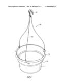
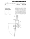
[0017]With reference to FIG. 1, a hanging basket in accordance with the present invention comprises a basket (10) and a suspension assembly (20).
[0018]The basket (10) has a bottom, a sidewall (11) and a connecting ring (12).
[0019]With further reference to FIG. 2, the sidewall (11) is formed around and protrudes up from the bottom of the basket (10) and has an edge, an outer surface and multiple mounting holes (111). The mounting holes (111) are formed through and around the sidewall (11) near the edge.
[0020]The connecting ring (12) is formed on and protrudes out from the edge of the sidewall (11) and has an outer edge, a lip (121) and multiple optional indentations (122). The lip (121) is formed around and protrudes down from the outer edge of the connecting ring (12) and has an outer surface. The indentations (122) are formed in the outer surface of the lip (121) and correspond respectively to the mounting holes (111) of the sidewall (11).
[0021]The suspension assembly (20) has an optional mounting connector (21), multiple suspension lines (22) and multiple basket connectors (23).
[0022]The mounting connector (21) attaches to an external object and may be implemented as a hook, a clamp, an eyebolt or the like.
[0023]The suspension lines (22) are connected to the mounting connector (21) and respectively to the basket connectors (23), and each suspension line (22) has an upper end and a lower end. The upper end of the suspension line (22) is connected to the mounting connector (21).
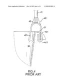
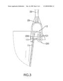
[0024]The basket connectors (23) are resilient and U-shaped, are attached respectively to the lower ends of the suspension lines (22) and are connected to the connecting ring (12) and respectively to the mounting holes (111), and each basket connector (23) has a cross member, two walls, a lip hook (231) and a post (232). The cross member of the basket connector (23) is connected to the lower end of a corresponding one of the suspension lines (22) and has two ends. The walls are formed respectively on and protrude down from the ends of the cross member, and each wall has a distal edge and an inner surface. The lip hook (231) is formed on the distal edge of one wall and bends parallel to the inner surface of the wall, is mounted selectively in a corresponding one of the indentations (122) of the connecting ring (12) and hooks the lip (121) of the connecting ring (12). The post (232) is formed on and protrudes transversely from the inner surface of the wall of the basket connector (23) opposite to the lip hook (231), is mounted selectively through a corresponding one of the mounting holes (111) of the sidewall (11) and abuts the lip hook (231).
[0025]With further reference to FIG. 3, the hanging basket as described has the following advantages. The lip hooks (231) of the basket connectors (23) may slide respectively into the indentations (122) of the connecting ring (12) until the lip hooks (231) of the basket connectors (23) and the lip (121) of the connecting ring (12) hook each other and the posts (232) of the basket connectors (23) are mounted in the mounting holes (111) of the basket (10). Thus, the basket (10) and the suspension assembly (20) are connected securely to each other. Even though the hanging basket may hang in high places, sway or bump other objects, the basket (10) will not detach from the suspension assembly (20).
[0026]Even though numerous characteristics and advantages of the present invention have been set forth in the foregoing description, together with details of the structure and features of the invention, the disclosure is illustrative only. Changes may be made in the details, especially in matters of shape, size, and arrangement of parts within the principles of the invention to the full extent indicated by the broad general meaning of the terms in which the appended claims are expressed.
User Contributions:
comments("1"); ?> comment_form("1"); ?>Inventors list |
Agents list |
Assignees list |
List by place |
Classification tree browser |
Top 100 Inventors |
Top 100 Agents |
Top 100 Assignees |
Usenet FAQ Index |
Documents |
Other FAQs |
User Contributions:
Comment about this patent or add new information about this topic:
| People who visited this patent also read: | |
| Patent application number | Title |
|---|---|
| 20100087027 | Large Scale Chemical Bath System and Method for Cadmium Sulfide Processing of Thin Film Photovoltaic Materials |
| 20100087026 | METHOD FOR MAKING SOLAR SUB-CELLS FROM A SOLAR CELL |
| 20100087025 | METHOD FOR DEFECT ISOLATION OF THIN-FILM SOLAR CELL |
| 20100087024 | DEVICE CAVITY ORGANIC PACKAGE STRUCTURES AND METHODS OF MANUFACTURING SAME |
| 20100087023 | LASER BEAM MACHINING METHOD AND LASER BEAM MACHINING APPARATUS |
Images included with this patent application:
 |  |
 |  |
 |
| Similar patent applications: | |
| Date | Title |
|---|---|
| 2009-08-27 | Hanging basket |
| New patent applications in this class: | |
| Date | Title |
|---|---|
| 2014-09-04 | Inclined bottle holding device |
| 2014-03-27 | Overhead storage system |
| 2014-01-30 | Fresh wipe hammock |
| 2013-06-27 | Suspension device for containers |
| 2013-06-13 | Joist storage system |
| New patent applications from these inventors: | |
| Date | Title |
|---|---|
| 2012-05-31 | Assembled container |
| 2009-03-26 | Plant pot |
| Top Inventors for class "Supports" | |
| Rank | Inventor's name |
|---|---|
| 1 | Jeffrey D. Carnevali |
| 2 | Yun-Lung Chen |
| 3 | Wen-Tang Peng |
| 4 | Zheng-Heng Sun |
| 5 | Zhan-Yang Li |