Patent application title: Plant Pot
Inventors:
Robert Chen (Taipei, TW)
IPC8 Class: AA01G904FI
USPC Class:
47 71
Class name: Plant husbandry receptacle for growing medium saucer
Publication date: 2009-03-26
Patent application number: 20090077882
Inventors list |
Agents list |
Assignees list |
List by place |
Classification tree browser |
Top 100 Inventors |
Top 100 Agents |
Top 100 Assignees |
Usenet FAQ Index |
Documents |
Other FAQs |
Patent application title: Plant Pot
Inventors:
Robert Chen
Agents:
Kamrath & Associates, P.A.;Suite 245
Assignees:
Origin: GOLDEN VALLEY, MN US
IPC8 Class: AA01G904FI
USPC Class:
47 71
Abstract:
A plant pot is used to plant or exhibit flowers and plants and has a pot
and a stand. The pot has a stand recess and multiple ribs. The stand
recess has an annular sidewall. The ribs are formed separately around the
sidewall of the stand recess. The stand is mounted securely below the pot
and has a mounting protrusion and multiple sliders. The mounting
protrusion corresponds to and is mounted securely in the stand recess and
has an annular wall. The sliders are formed separately around the annular
wall of the mounting protrusion, correspond to the ribs and are held on
the ribs to mount the stand securely on the pot to prevent the stand from
detaching from the plant pot to improve safety of use.Claims:
1. A plant pot comprising:a pot being havingan outer bottom;a stand recess
being cylindrical, being formed in the outer bottom of the stand recess
and having an annular sidewall; andmultiple ribs being formed separately
on and protruding transversely around the sidewall of the stand recess;
anda stand being a vertical brace, being mounted securely below the pot
and havinga lower end;an upper end;a mounting protrusion being formed on
and protruding from the upper end of the stand, corresponding to and
being mounted securely in the stand recess and having an annular wall;
andmultiple sliders being formed separately on and protruding
transversely around the annular wall of the mounting protrusion,
corresponding to and being held on the ribs.
2. The plant pot as claimed in claim 1, wherein each rib is L-shaped.
3. The plant pot as claimed in claim 2, wherein the stand recess is tapered.
4. The plant pot as claimed in claim 3, wherein the stand further has a base being formed around the lower end of the stand and being disk-shaped.
Description:
BACKGROUND OF THE INVENTION
[0001]1. Field of the Invention
[0002]The present invention relates to a plant pot, and more particularly to a plant pot with a stand mounted below the plant pot.
[0003]2. Description of Related Art
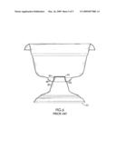
[0004]With reference to FIG. 6, a conventional plant pot comprises a pot (40) and a stand (50).
[0005]The pot (40) has an outer bottom and a stand recess (41). The stand recess (41) is a tapered cylinder and is formed in the outer bottom of the pot (40).
[0006]The stand (50) is mounted securely below the pot (40) to elevate the plant pot for exhibiting and has a base (51), a brace (52) and a mounting protrusion (53). The base (51) stands on the ground and may be disk shaped. The brace (52) is formed on and protrudes from the base (51) and has an upper end. The mounting protrusion (53) is formed on and extends from the upper end of the brace (52), corresponds to and is mounted in the stand recess (41).
[0007]However, the pot (40) is merely held on the stand (50) by gravity, with no engaging structure and therefore, might fall off during earthquakes or if accidentally hit by passing children. Moreover, the pot (40) may topple if an elderly person rests their weight on the pot (40) to bend over to attend to the pot (40). If the plant pot needs to be moved, the stand (50) drops out from the pot (40) during moving the plant pot may hurt a mover's foot or damage the stand (50).
[0008]To overcome the shortcomings, the present invention provides a plant pot to mitigate or obviate the aforementioned problems.
SUMMARY OF THE INVENTION
[0009]The main objective of the invention is to provide a plant pot, which has a stand mounted securely below the plant pot.
[0010]The plant pot is used to plant or exhibit flowers and plants and has a pot and a stand. The pot has a stand recess and multiple ribs. The stand recess has an annular sidewall. The ribs are formed separately around the sidewall of the stand recess. The stand is mounted securely below the pot and has a mounting protrusion and multiple sliders. The mounting protrusion corresponds to and is mounted securely in the stand recess and has an annular wall. The sliders are formed separately around the annular wall of the mounting protrusion, correspond to the ribs and are held on the ribs to mount the stand securely on the pot to prevent the stand from detaching from the plant pot to improve safety of use.
[0011]Other objectives, advantages and novel features of the invention will become more apparent from the following detailed description when taken in conjunction with the accompanying drawings.
BRIEF DESCRIPTION OF THE DRAWINGS
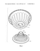
[0012]FIG. 1 is a perspective view of a plant pot in accordance with the present invention;
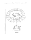
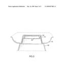
[0013]FIG. 2 is an enlarged perspective view of the plant pot in FIG. 1;
[0014]FIG. 3 is an enlarged cross-sectional front view of the plant pot in FIG. 1;
[0015]FIG. 4 is an operational cross-sectional top view of the plant pot in FIG. 1, shown disengaged;
[0016]FIG. 5 is an operational cross-sectional top view of the plant pot in FIG. 1, shown engaged; and
[0017]FIG. 6 is a cross-sectional front view of a conventional plant pot in accordance with the prior art.
DETAILED DESCRIPTION OF PREFERRED EMBODIMENT
[0018]With reference to FIGS. 1 and 2, a plant pot in accordance with the present invention is used to plant or exhibit flowers and plants and comprises a pot (10) and a stand (20).
[0019]The pot (10) is used to hold the soil, the flowers and plants and has an outer bottom, a stand recess (1) and multiple ribs (12).
[0020]With further reference to FIG. 3, the stand recess (11) is substantially cylindrical, is formed in the outer bottom of the stand recess (11), may be tapered and has an annular sidewall.
[0021]The ribs (12) are formed separately on and protrude transversely around the sidewall of the stand recess (11). Each rib (12) may be L-shaped to form an entry and a stop and is arranged in the same direction.
[0022]The stand (20) is a vertical brace, is mounted securely below the pot (10) to elevate and support the pot (10), and has a lower end, an upper end, an optional base (21), a mounting protrusion (23) and multiple sliders (24).
[0023]The base (21) is formed around the lower end of the stand (20) to stand on a surface such as a patio, garden or ground and is disk-shaped.
[0024]The mounting protrusion (23) is formed on and protrudes from the upper end of the stand (20), corresponds to and is mounted securely in the stand recess (11) and has an annular wall.
[0025]With further reference to FIGS. 4 and 5, the sliders (24) are formed separately on and protrude transversely around the annular wall of the mounting protrusion (23), correspond to the ribs (12) and slide into the entry of the ribs (12) to be held on the ribs (12) to mount the stand (20) securely below the pot (10).
[0026]Consequently, having the ribs (12) and the sliders (24) engaging with each other improves connection between the pot (10) and the stand (20) so preventing accidental disconnection and improving safety of use.
[0027]Even though numerous characteristics and advantages of the present invention have been set forth in the foregoing description, together with details of the structure and function of the invention, the disclosure is illustrative only, and changes may be made in detail, especially in matters of shape, size, and arrangement of parts within the scope of the appended claims.
User Contributions:
comments("1"); ?> comment_form("1"); ?>Inventors list |
Agents list |
Assignees list |
List by place |
Classification tree browser |
Top 100 Inventors |
Top 100 Agents |
Top 100 Assignees |
Usenet FAQ Index |
Documents |
Other FAQs |
User Contributions:
Comment about this patent or add new information about this topic:
Images included with this patent application:
 |  |
 |  |
 |  |
| New patent applications in this class: | |
| Date | Title |
|---|---|
| 2016-05-12 | Water catching and draining saucer and complementary catch basin |
| 2015-01-15 | Vertical living wall planter |
| 2012-10-11 | Plant water catch basin |
| 2010-07-08 | Stable flowerpot system |
| 2008-12-04 | Crate and planting pot |
| New patent applications from these inventors: | |
| Date | Title |
|---|---|
| 2012-05-31 | Assembled container |
| 2009-08-27 | Hanging basket |
| 2009-03-26 | Hanging basket |
| Top Inventors for class "Plant husbandry" | |
| Rank | Inventor's name |
|---|---|
| 1 | Donald E. Weder |
| 2 | Frank M. Stewart |
| 3 | Bruce G. Kania |
| 4 | Michael R. Klemme |
| 5 | David S. Mackenzie |