Patent application title: Advanced wireless pointing device
Inventors:
Miha Abrahamsberg (Ribnica, SI)
IPC8 Class: AG06F30346FI
USPC Class:
345158
Class name: Display peripheral interface input device cursor mark position control device including orientation sensors (e.g., infrared, ultrasonic, remotely controlled)
Publication date: 2016-01-07
Patent application number: 20160004334
Abstract:
Subject of the invention is a method to calculate the point of a display
device to which we are pointing to and a device of which one part is a
part of a pointing device (like computer mouse or any other electronic
pointing device), as part of game controllers or (smart) TV remote
controllers. Also a method to calculate the point of the display device
to which we are pointing. The device consists of a part that we place to
a fixed position relative to the display device (or attached to it or
built-in) and a part that can be hand held or worn or built-in another
device (game or TV controllers). Both parts have several transceivers
(receiver and transmitter) that communicate with each other to ascertain
the distance from one to the other. We calculate the distance from the
time spent for the signal to get from one transmitter to the other (and
back) and the velocity of the signal. For communication, different wave
propagations can apply (sound or electromagnetic waves). Knowing the
position of all transceivers, we can calculate the point on the display
device to which the person is pointing.
The described technical solution represents a huge leap forward in
wireless devices, where it is important to know where the user is
pointing the device. There are numerous possible practical applications.
For example, a computer mouse which you can hold in your hands and use as
normal for presentations, a remote control for so-called Smart TVs (which
now have quite slow response and lack of precision), and finally the
controls (game pads) for computer games (imagine a controller in the form
of a weapon being used in an action game and which "knows" where exactly
to point on the display or move its beam of sight).Claims:
1. Device to use as a wireless pointing device and a method to calculate
the point of the display device to which we are pointing. The device
consists of a part that we place to a fixed position relative to the
display device (or attached to it or built-in) and a part that can be
hand held or worn or built-in into another device. Both parts have
several transceivers (receiver and transmitter) that communicate with
each other to ascertain the distance from one to the other. The method
enables the calculation of the exact point on the display device to which
the person is pointing.
2. Device to use as a wireless pointing device as part of game controllers or (smart) TV remote controllers and a method to calculate the point of the display device to which we are pointing. The device consists of a part that we place to a fixed position relative to the display device (or attached to it or built-in) and a part that can be hand held or worn or built-in into another device. Both parts have several transceivers (receiver and transmitter) that communicate with each other to ascertain the distance from one to the other. The method enables the calculation of the exact point on the display device to which the person is pointing.
Description:
[0001] I would like to claim the benefit of the provisional application
No. U.S. 62/020,413, filling date Jul. 03, 2014, applicant: Miha
Abrahamsberg
[0002] The subject of the invention is a method to calculate the point of a display device to which we are pointing to and a device of which one part is a part of a pointing device (like a computer mouse or any other electronic pointing device), as part of game controllers or (smart) TV remote controllers. The device consists of a part that we place to a fixed position relative to the display device (or attached to it or built-in) and a part that can be hand held or worn. Both parts have several transceivers (receiver and transmitter) that communicate with each other (ping) to ascertain the distance from one to the other. We calculate the distance from the time spent for the signal to get from one transmitter to the other (and back) and the velocity of the signal. For communication, different wave propagations can apply (sound or electromagnetic waves). Knowing the position of all transceivers, we can calculate the point on the display device to which the person is pointing.
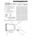
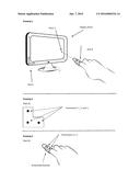
[0003] In the drawings attached there are three different views presenting one possible practical application of the invention. Drawing 1 depicts a display device with an imaginary coordinate system (X, Y, Z), attached part (part A) to the display device and the other part (part B) worn on a person's finger. The person is using the invention in a manner of a computer mouse. Drawing 2 just shows a more detailed view of the part with three transceivers (the fixed part of the invention) and drawing 3 a more detailed view of the part with two transceivers (the part of the invention that we use, hold or wear).
[0004] The invention relates to a method (described below) and a device with transceivers that communicate with each other in order to calculate the distances between them. First part (Part A see Drawing 1) has known 3-dimensional coordinates (in a given 3-dimensional system* of coordinates) of all the transceivers. Based on the calculated distances to transceivers on the other part (Part B see Drawing 1), the coordinates of the transceivers on the latter part are calculated. As a result, we get the position and orientation of part B in a given 3-dimensional system and subsequently the point on the display device.
*a system represents the room or space surrounding the device (invention) and the display device on which it used.
[0005] Part A is attached to (or part of) the display device (computer screen, TV, mobile computer screen etc.) and has three transceivers T1, T2, T3 (see Drawing 1 and 2). Distance between T1 and T2 is the same as T2 to T3. Point T2 is also the origin of the three dimensional space defined by axes X, Y, Z. Given part A is attached (for example) to the lower left corner of the display device then from the users point of view X increases from left to right, Y increases from bottom to top and Z increases from the display device towards the user (see Drawing 1). We define the coordinates of the transceivers as:
T1(X1, Y1, Z1)
T2(X2, Y2, Z2)
T3(X3, Y3, Z3) [1]
Since T2 is on the origin of the coordinate system, we can simplify as:
T1(X1, 0, 0)
T2(0, 0, 0)
T3(0, Y3, 0) [2]
Part B can be hand held or worn. It has two transceivers T4 and T5 and action/click buttons (see drawing 1 and 3). The coordinates of transceivers are unknown:
T4(X4, Y4, Z4)
T5(X5, Y5, Z5) [3]
Speed of wave propagation between transceivers (v) depends on the type of wave. For electromagnetic propagation we use the speed of light, for sound we use the speed of sound.
[0006] We calculate all the distances between all transceivers on part A (T1, T2, T3) and part B (T4 and T5). First distance (d14) is the distance between transceiver T1 and T4 and time t14 is the time for the signal to get from T1 to T4 and back. The same process is carried out (analogically) for other distances. We calculate all as:
d 14 = t 14 2 * v d 15 = t 15 2 * v d 24 = t 24 2 * v d 25 = t 25 2 * v d 34 = t 34 2 * v d 35 = t 35 2 * v [ 4 ] ##EQU00001##
[0007] To avoid the problem of reading the same signal more than one time (problem of signals bouncing of an object (walls etc.) in a closed space), we can either assign unique identifications (IDs) to each signal, store the ID when signal is first read and ignore already read IDs or we can (slightly) change the frequency of each signal (frequency rotation), store the frequency information when signal is first read and ignore already read signals, or we can have to consecutive signals, first informing us of which frequency to expect from the "ping" signal and then only read the signal on this frequency once and ignore others (bounced).
[0008] Using the formula to calculate distances in 3-D space, we can also define all the above distances as:
d142=(X1-X4)2+(Y1-Y4)2+(Z1-- Z4)2
d152=(X1-X5)2+(Y1-Y5)2+(Z1-- Z5)2
d242=(X2-X4)2+(Y2-Y4)2+(Z2-- Z4)2
d252=(X2-X5)2+(Y2-Y5)2+(Z2-- Z5)2
d342=(X3-X4)2+(Y3-Y4)2+(Z3-- Z4)2
d352=(X3-X5)2+(Y3-Y5)2+(Z3-- Z5)2 [5]
[0009] The system is significantly simplified when we insert known (predefined) coordinates for points T1, T2 and T3 (see [2] above). We simply get two systems of three equations with three unknown coordinates/variables (X4, Y4, Z4 and X5, Y5, Z5).
d142=X42-2X4+1+Y42+Z42
d242=X42+Y42+Z42
d342=X42+Y42-2Y4+1+Z42 [6]
And
[0010] d152=X52-2X5+1+Y52+Z52
d252=X52+Y52+Z52
d352=X52+Y52-2Y5+1+Z52 [7]
[0011] From [6] we can now calculate the coordinates of T4 and for T5 from [7]:
T 4 ( X 4 , Y 4 , Z 4 ) = ( d 24 2 - d 14 2 + 1 2 , d 24 2 - d 34 2 + 1 2 , d 24 2 - X 4 2 - Y 4 2 ) ##EQU00002## T 5 ( X 5 , Y 5 , Z 5 ) = ( d 25 2 - d 15 2 + 1 2 , d 25 2 - d 35 2 + 1 2 , d 25 2 - X 5 2 - Y 5 2 ) ##EQU00002.2##
[0012] Given that the pointing device should always be in front of the display device (see Drawing 1), we can limit both results (T4 and T5) to only positive Z coordinates. This way we only get one solution for both points.
[0013] Finally, with both T4 and T5 known we have the equation for a line in 3-D space (that Part B projects towards the display device):
X - X 4 X 5 - X 4 = Y - Y 4 Y 5 - Y 4 = Z - Z 4 Z 5 - Z 4 ##EQU00003##
[0014] Having the display device (its plane in 3-D space) at Z=0 the point (T0, see drawing 1) on the display device to which the user points is simply:
X = - Z 4 Z 5 - Z 4 ( X 5 - X 4 ) + X 4 ##EQU00004## Y = - Z 4 Z 5 - Z 4 ( Y 5 - Y 4 ) + Y 4 ##EQU00004.2## Z = 0 ##EQU00004.3##
[0015] Having calculated point T0 we know exactly to which point on the display device the user is pointing to (note: in practice the computer driver will adjust the calculated point to the actual display resolution and "forward" the information to the operating system).
User Contributions:
Comment about this patent or add new information about this topic:
Images included with this patent application:
 |  |
 |  |
| Similar patent applications: | |
| Date | Title |
|---|---|
| 2015-10-22 | Wearable wireless tongue controlled devices |
| 2016-01-14 | System and method for controlling divided screens independently through mapping with input devices |
| 2015-11-26 | Display device and image processing device |
| 2015-10-15 | Display apparatus and method for displaying screen images from multiple electronic devices |
| 2015-10-22 | Automated cardiopulmonary resuscitation device with a display |
| New patent applications in this class: | |
| Date | Title |
|---|---|
| 2019-05-16 | System and method for distributed device tracking |
| 2018-01-25 | System and method for providing absolute coordinate and zone mapping between a touchpad and a display screen |
| 2018-01-25 | Sensitivity adjustment for a pointing device |
| 2018-01-25 | Content acquiring method and apparatus, and user equipment |
| 2017-08-17 | Systems and methods of direct pointing detection for interaction with a digital device |
| New patent applications from these inventors: | |
| Date | Title |
|---|---|
| 2012-02-23 | Advanced positioning system |
| Top Inventors for class "Computer graphics processing and selective visual display systems" | |
| Rank | Inventor's name |
|---|---|
| 1 | Katsuhide Uchino |
| 2 | Junichi Yamashita |
| 3 | Tetsuro Yamamoto |
| 4 | Shunpei Yamazaki |
| 5 | Hajime Kimura |