Patent application title: VALVE SYSTEM FOR INTERNAL COMBUSTION ENGINES
Inventors:
Holger Paffrath (Pulheim, DE)
IPC8 Class: AF02M2507FI
USPC Class:
13762548
Class name: Systems multi-way valve unit reciprocating valve unit
Publication date: 2015-04-30
Patent application number: 20150114502
Abstract:
A valve system for an internal combustion engine includes a housing, a
drive unit arranged in the housing, at least one valve unit, at least two
gas inlet ducts, and a gas outlet duct. The at least one valve unit
comprises at least one valve rod, at least one valve closure body, and at
least one valve seat. The at least one valve unit is connected to the
drive unit. The at least two gas inlet ducts form exactly one of the at
least one valve seat which is configured to cooperate with exactly one of
the at least one valve closure body.Claims:
1. A valve system for an internal combustion engine, the valve system
comprising: a housing; a drive unit arranged in the housing; at least one
valve unit comprising at least one valve rod, at least one valve closure
body, and at least one valve seat, the at least one valve unit being
connected to the drive unit; at least two gas inlet ducts; and a gas
outlet duct, wherein, the at least two gas inlet ducts form exactly one
of the at least one valve seat which is configured to cooperate with
exactly one of the at least one valve closure body.
2. The valve system as recited in claim 1, wherein the valve system is provided for exhaust gas recirculation.
3. The valve system as recited in claim 1, wherein the exactly one of the at least one valve seat comprises a molded-in seat ring.
4. The valve system as recited in claim 1, further comprising at least one web element, wherein the at least two gas inlet ducts are separated from each other by the at least one web element.
5. The valve system as recited in claim 4, wherein, in a closed state of the exactly one valve closure body, the at least one web element is configured to end before the exactly one valve closure body.
6. The valve system as recited in claim 1, wherein the at least two gas inlet ducts comprise a circumferential wall section, the circumferential wall section being directed to the gas outlet and being configured to form the exactly one of the at least one valve seat.
7. The valve system as recited in claim 4, wherein the at least one valve rod comprises a sealing element at an end directed to the at least one valve seat, the sealing element being configured to engage the at least one web element.
8. The valve system as recited in claim 7, wherein the sealing element and the at least one web element are configured as a tongue-and-groove system.
9. The valve system as recited in claim 8, wherein the sealing element comprises spring steel.
10. The valve system as recited in claim 1, wherein the valve closure body is configured to be resiliently supported at the at least one valve rod.
Description:
CROSS REFERENCE TO PRIOR APPLICATIONS
[0001] Priority is claimed to German Patent Application No. DE 10 2013 112 018.0, filed Oct. 31, 2013. The entire disclosure of said application is incorporated by reference herein.
FIELD
[0002] The present invention relates to a valve system for an internal combustion engine, in particular, for exhaust gas recirculation, comprising a housing in which a drive unit is arranged that, in terms of drive, is connected with at least one valve unit, and further comprising at least two gas inlet ducts and one gas outlet duct, the valve unit comprising at least one valve rod, at least one valve closure body, and at least one valve seat.
BACKGROUND
[0003] Such valve systems have previously been described. DE 10 2008 027 490 A1,for example, describes a valve system in which two gas inlet ducts are connected with an outlet duct for exhaust gas recirculation. The two gas inlet ducts each have a valve seat that can be closed with a valve closing body of the respective valve. Both valves are driven by a common drive unit. The separation of the gas inlet ducts is particularly important in the high-pressure EGR area to avoid negative effects on the gas dynamics in the exhaust gas system and the turbocharger. It should be understood, however, that although only one drive unit is used, two independent valves must basically be provided for two gas inlet ducts, which must also be securely coupled with the drive unit via a transmission system, thereby causing considerable assembly effort and high costs.
SUMMARY
[0004] An aspect of the present invention is to provide a valve system which allows for a simple and economic separation of the gas inlet ducts.
[0005] In an embodiment, the present invention provides a valve system for an internal combustion engine which includes a housing, a drive unit arranged in the housing, at least one valve unit, at least two gas inlet ducts, and a gas outlet duct. The at least one valve unit comprises at least one valve rod, at least one valve closure body, and at least one valve seat. The at least one valve unit is connected to the drive unit. The at least two gas inlet ducts form exactly one of the at least one valve seat which is configured to cooperate with exactly one of the at least one valve closure body.
BRIEF DESCRIPTION OF THE DRAWINGS
[0006] The present invention is described in greater detail below on the basis of embodiments and of the drawings in which:
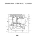
[0007] FIG. 1 shows a sectional perspective view of a valve system according to the present invention;
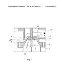
[0008] FIG. 2 shows a cross-sectional view of the valve system in FIG. 1 with the valve unit open; and
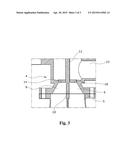
[0009] FIG. 3 shows a cross-sectional view of the valve system in FIG. 1 with the valve unit closed.
DETAILED DESCRIPTION
[0010] In an embodiment, the present invention provides that the gas inlet ducts form exactly one valve seat which cooperates with exactly one valve closure body. In this manner, it is possible to manufacture a valve system having a plurality of gas inlet ducts and one gas outlet duct in a particularly simple and economic manner. The complex transmission structure of the prior art which couples the two individual valves can be omitted without substitution. It may be particularly advantageous in this regard if, for example, the valve seat of the gas inlet ducts comprises a molded-in seat ring.
[0011] In an embodiment of the present invention, the gas inlet ducts can, for example, be separated from each other by at least one web element. The valve seat can, for example, be formed by a circumferential wall section of the gas inlet ducts that is directed towards the gas outlet duct. The web element can, for example, end a short distance from the valve closure body. It is thereby provided that the valve closure body is not over-determined when resting on the valve seat. With a narrow gap of a dimension of 2/10 mm, for example, the mutual influence among the gas inlet ducts is very little or negligible. The valve rod can, for example, additionally be provided with a sealing element at the end facing the valve seat, which sealing element engages the web element. The sealing element and the web element can, for example, be designed as a tongue-and-groove system. The sealing element can alternatively be made from spring steel.
[0012] In an embodiment of the present invention, the valve body can, for example, be supported at the valve rod in a resilient manner, whereby a sealed contact of the valve closure body with the valve seat is provided in a simple manner.
[0013] The present invention is explained hereinafter in greater detail under reference to the drawings.
[0014] FIG. 1 shows a perspective sectional view of a detail of a valve system 2 for internal combustion engines for exhaust gas recirculation purposes. The valve system 2 has a multi-part housing 4 which, in the present embodiment, is connected with a two-channel exhaust gas line 5. It should be understood that the housing 4 can also be designed as a single-piece housing. The exhaust gas line 5 may further have a different design; in particular, it may have more than two exhaust gas channels. The multi-part housing 4 in the present case is built from a first housing part 20 and a second housing part 22, wherein a drive unit (not illustrated in detail) is provided in the second housing part 22. Two gas inlet ducts 6, 8 separated by a web element 18 are provided in the first housing part 20, which ducts communicate with a gas outlet duct 10 in the open state of a valve unit. The valve unit has a valve rod 12 and a valve closure body 14 which cooperates with a valve seat 16 in a manner known per se. The valve closure body 14 can be supported resiliently on the valve rod 12 in order to provide a secure abutment of the valve closure body 14 on the valve seat 16. The valve seat 16 of the gas inlet ducts 6, 8 can have a molded-in seat ring (not illustrated in the drawings). The valve seat 16 is formed by a circumferential wall section 19 of the gas inlet ducts 6, 8 that is directed towards the gas outlet duct 10 (shown in FIG. 2).
[0015] As is clearly visible in particular in FIG. 3, the web element 18 ends a short distance from the valve closure body 14, whereby, in the shown embodiment, a sufficient separation of the gas inlet ducts 6, 8 is provided and an over-determination of the abutment of the valve closure body 14 is prevented in a particularly simple and economic manner. It is also conceivable, however, to provide a sealing element 17 at the valve rod 12 or at the valve closure body 14, respectively, which abuts on the web element 18 in a sealing manner (see FIG. 2). It is conceivable in this context, for example, to use a tongue-and-groove system as the sealing element 17. The sealing element 17 can further be made from spring steel. The sealing element 17 can in this case be an integral part of the valve rod 12, however, it may also be designed as an individual part. It is also conceivable to manufacture the valve rod 12 or the valve closure body 14 from stainless steel.
[0016] FIG. 2 shows a sectional view of the valve system 2 in the open position of the valve closure body 14. The arrows show a possible exhaust gas flow from the gas inlet ducts 6, 8 into the gas outlet duct 10.
[0017] FIG. 3 shows the valve system 2 with the valve closure body closed, wherein the small distance of the web element 18 to the valve closure body 14 or the valve rod 12, respectively, provides a sufficient separation of the gas inlet ducts 6, 8. It should be clear based on FIG. 3 that a complete sealed separation of the gas inlet ducts 6, 8 can be achieved in a simple manner by using a corresponding sealing element 17 on the valve closure body 14 or the valve rod 12. In the context of the possibilities mentioned before, it is also conceivable to provide the side of the valve rod 12 directed towards the web element 18 with a corresponding shape that could engage the web element 18 as the sealing element.
[0018] The present invention is not limited to embodiments described herein; reference should be had to the appended claims.
User Contributions:
Comment about this patent or add new information about this topic:
| People who visited this patent also read: | |
| Patent application number | Title |
|---|---|
| 20170047317 | Electrostatic Discharge Device |
| 20170047316 | SEMICONDUCTOR DEVICE |
| 20170047315 | Method of Manufacturing a Multi-Chip Semiconductor Power Device |
| 20170047314 | LED MODULE |
| 20170047313 | METHOD FOR FABRICATING GLASS SUBSTRATE PACKAGE |
Images included with this patent application:
 |  |
 |  |
| Similar patent applications: | |
| Date | Title |
|---|---|
| 2015-04-30 | Rotary shear valve assembly with hard-on-hard seal surfaces |
| 2015-04-23 | Systems and methods for cascading burst discs |
| 2015-04-23 | Clamshell housing for dispensing tube of metering dispenser |
| 2015-04-30 | Valve and construction machine with the same |
| 2015-04-30 | Shut-off valve with heating element, in particular for a rail vehicle |
| New patent applications in this class: | |
| Date | Title |
|---|---|
| 2018-01-25 | Electromagnetic actuator |
| 2016-07-14 | Flow control valve for construction equipment |
| 2016-06-02 | Slow-shift spm valve |
| 2016-06-02 | Electromagnetic valve for high-pressure cryogenic gas |
| 2016-05-26 | Solenoid valve |
| New patent applications from these inventors: | |
| Date | Title |
|---|---|
| 2016-01-28 | Exhaust gas valve device for an internal combustion engine |
| 2014-06-19 | Side channel blower having a plurality of feed channels distributed over the circumference |
| 2012-12-20 | Valve device for internal combustion engines |
| 2009-10-15 | Exhaust gas recirculation system for an internal combustion engine |
| 2009-01-22 | Combined check and control valve |
| Top Inventors for class "Fluid handling" | |
| Rank | Inventor's name |
|---|---|
| 1 | Nobukazu Ikeda |
| 2 | Kouji Nishino |
| 3 | Ryousuke Dohi |
| 4 | Kevin T. Peel |
| 5 | Huasong Zhou |