Patent application title: CO2 RECYCLING DEVICE AND CO2 RECYCLING SYSTEM
Inventors:
Assignees:
T-SUPPORT CO., LTD.
IPC8 Class: AC23C16511FI
USPC Class:
118723MW
Class name: With treating means (e.g., jarring) by creating electric field (e.g., gas activation, plasma, etc.) microwave gas energizing means (e.g., 2.45 gigahertz, microwave plasma, etc.)
Publication date: 2015-01-08
Patent application number: 20150007773
Abstract:
To provide a CO2 recycling device which is compact and with which
electricity consumption can be reduced. The invention is a device for
manufacturing multilayer carbon nanotubes, carbon onions or nano-carbons,
using a microwave plasma CVD method, taking the CO2 gas within a
carbon monoxide-containing gas as the carbon source. The device comprises
a microwave oscillator, a microwave waveguide and a reaction tube
provided within the microwave waveguide, and a gas inlet pipe and an
exhaust pipe are configured from the reaction tube which returns within
the microwave waveguide and a ceramic-type heater provided on the inner
wall of the gas inlet pipe. Then, microwave plasma is generated at the
position where the reaction tube returns, and the multilayer carbon
nanotube, carbon onion or nano-carbon formed is adhered to the inner wall
of the exhaust pipe.Claims:
1. A CO2 recycling device that synthesizes either carbon nanotube,
carbon onion and/or nano-carbons with using microwave plasma CVD of
CO2 gas which is contained in hydrocarbon gases, the device
comprising: a microwave generator; a microwave guide; a reaction tube
installed in the above mentioned microwave guide, which is designed to
turn back the gas from the gas inlet to the vacuum evacuation part inside
the wave guide; and a ceramics heater at the position of gas inlet,
wherein the device generates the plasma at the reaction tube to produce
and deposit multi-wall carbon nanotube, carbon onion and/or nano-carbons.
2. A CO2 recycling device that synthesizes either carbon nanotube, carbon onion and/or nano-carbons with using microwave plasma CVD of CO2 gas which is contained in hydrocarbon gases, the device comprising: a microwave generator; a coaxial microwave guide; a reaction tube connected to the above mentioned coaxial microwave guide, which is designed to turn back the gas from the gas inlet to the vacuum evacuation part inside the wave guide; and a ceramics heater at the position of gas inlet, wherein the device generates the plasma at the reaction tube to produce and deposit multi-wall carbon nanotube, carbon onion and/or nano-carbons.
3. The CO2 recycling device according to claim 1, wherein the reaction tube is the U-shaped quartz tube, and one end functions as the gas inlet, while the other as vacuum evacuation tube.
4. The CO2 recycling device according to claim 1, wherein the reaction tube is composed of two tubes with different diameters, wherein the tube with smaller diameter is connected to the gas inlet, wherein the tube with larger diameter is connected to the vacuum evacuation.
5. The CO2 recycling device according to claim 3, wherein the reaction tube has the shapes of spiral and zigzag, which enable the gas to travel for a long path.
6. The CO2 recycling device according to claim 1, wherein the ceramics heater is silicon carbide (SiC).
7. The CO2 recycling device according to claim 1, wherein the ceramics heater is heated by the microwave irradiation.
8. The CO2 recycling device according to claim 1, wherein a pressure inside the reaction tube is 100 to 200 Pa.
9. The CO2 recycling device according to claim 1, wherein the reaction tube is made of transparent quartz, non-transparent quartz, ceramics or metals.
10. The CO2 recycling device according to claim 1, wherein a size of the microwave guide, a length of which is smaller than 400 mm, the width smaller than 200 mm, and the height smaller than 100 mm.
11. The CO2 recycling device according to claim 1, wherein the microwave guide that is connected to the microwave matching device.
12. The CO2 recycling device according to claim 2, wherein the coaxial microwave cable that is connected to the coaxial type three-stub tuner.
13. A CO2 recycling system is characterized by the multiple use of the CO2 recycling device according to claim 1, wherein the vacuum evacuation part of one apparatus is connected to the gas inlet part of the other apparatus.
14. The CO2 recycling system according to claim 13, wherein the system has a CO decomposition ability which decomposes the exhausted carbon monoxide gas (CO) from the first apparatus by the next apparatus.
15. The CO2 recycling device according to claim 2, wherein the reaction tube is the U-shaped quartz tube, and one end functions as the gas inlet, while the other as vacuum evacuation tube.
16. The CO2 recycling device according to claim 2, wherein the reaction tube is composed of two tubes with different diameters, wherein the tube with smaller diameter is connected to the gas inlet, wherein the tube with larger diameter is connected to the vacuum evacuation.
17. The CO2 recycling device according to claim 2, wherein the ceramics heater is silicon carbide (SiC).
18. The CO2 recycling device according to claim 2, wherein the ceramics heater is heated by the microwave irradiation.
19. The CO2 recycling device according to claim 2, wherein a pressure inside the reaction tube is 100 to 200 Pa.
20. The CO2 recycling device according to claim 2, wherein the reaction tube is made of transparent quartz, non-transparent quartz, ceramics or metals.
Description:
TECHNICAL FIELD
[0001] The present invention is concerned with the apparatus and system which reduce the amount of carbon dioxide (CO2) from the exhaust gas of automobiles and ships by solidifying carbon (C), and further the synthesis of such value-added advanced carbon materials as carbon nanotube (CNT), carbon onion, carbon nanohorn, etc.
BACKGROUND ART
[0002] It is generally well accepted that the decomposition of carbon dioxide (CO2) is much harder than carbon monoxide (CO) and hydrocarbons (HC), because the energy required for decomposing CO2 is very high.
[0003] Under these circumstances, Ohmae invented and proposed the CO2 recycling apparatus which synthesized either multi-walled carbon nanotube, carbon onion and/or other nano-carbons by decomposing carbon dioxide (CO2 gas) with microwave plasma CVD (patent literatures 1).
[0004] The CO2 recycling apparatus proposed earlier was equipped with the substrate on which catalyst such as iron was deposited, the heating system which heat the substrate, gas introduction which introduced CO2 gas to the surface of substrate, microwave plasma generator which ignited microwave plasma on the substrate surface, and the power supply which supplied electric power to the microwave plasma generator.
[0005] [Patent literature 1] International Publication Pamphlet WO 2011/004609 A1
OUTLINE OF THE INVENTION
Problems to be Solved by the Invention
[0006] The above stated CO2 recycling apparatus, now under proposing, composed of microwave plasma generator and muffle furnace around the quartz tube with a length of 800 mm, and the nano-carbons were deposited on the surface of substrate placed in the furnace by decomposing CO2 gas with hydrogen (H2) as a carrier gas. Thus the apparatus under proposing had the problem of increased electricity consumption, because the sum of electric consumption of microwave generator and muffle furnace became large.
[0007] In addition, the large dimension of apparatus was another problem, because one of the major components was the quartz tube with the length of 800 mm.
[0008] From these viewpoints, the present invention aims the establishment of CO2 recycling apparatus with the compact size and low electricity consumption.
Means to Solve the Objects
[0009] To solve the above problems, the present inventors accomplished the CO2 recycling apparatus with many trial and errors.
[0010] The newly invented CO2 recycling apparatus synthesizes either multi-wall carbon nanotube, carbon onion or other nano-carbons using CO2 gas contained in hydrocarbon gases with a use of microwave plasma CVD, and is composed of the major components shown below.
1) Microwave Generator
[0011] The magnetron in commercially available microwave oven, 2.45 GHz frequency and 500 W maximum power, is applicable to the microwave generator.
2) Microwave Guide
[0012] Microwave is resonated by the back and force of microwave.
3) Reaction Tube
[0013] Reaction tube is installed in the microwave guide, and gas inlet and vacuum evacuation are folded back in this reaction tube. By this design, the length of quartz tube can be shortened, and the apparatus becomes compact.
[0014] It is advantageous to increase the path of gas flow. Therefore, spiral shaped tube or zigzag tube seems applicable.
4) Ceramics Heater Stored Inside of Gas Inlet
[0015] With this ceramics heater, the temperature is increased by the irradiation of microwave. The ceramics heater is needed mainly for depositing nano-carbons from CO2 gas. However, the influence of ceramics heater on the reduction rate of CO2 gas is small.
[0016] With major components shown above, microwave plasma is generated in the reaction tube to deposit multi-wall carbon nanotube, carbon onion or other nano-carbons at the wall of reaction tube. The carbons can be deposited on the surface of substrate by putting such substrate in the reaction tube.
[0017] Moreover, plasma CVD is effective in decomposing fluorocarbon gases or other toxic gases, and the present CO2 recycling apparatus can be used in order to decompose hydrocarbon gases containing fluorocarbon or other toxic gases.
[0018] The CO2 recycling apparatus also works by using coaxial microwave cable instead of microwave guide, and the microwave plasma generates at the reaction tube connected to this coaxial microwave cable.
[0019] In other words, the present CO2 recycling apparatus synthesizes multi-wall carbon nanotube, carbon onion or other nano-carbons from CO2 gas contained in hydrocarbon gases by the microwave plasma CVD, and is equipped with microwave generator, microwave coaxial cable, and the reaction tube connected to the coaxial cable. The plasma is maintained in the reaction tube where gas inlet and vacuum evacuation are turned back. The present CO2 recycling apparatus contains ceramics heater inside of the gas inlet.
[0020] The reaction tube described in the present invention typically is the U-shaped quartz tube, and one end is connected to the gas inlet, while the other to vacuum evacuation.
[0021] By this design, the length of quartz tube can be shortened, and the apparatus becomes compact.
[0022] It is advantageous to increase the path of gas flow. Therefore, spiral shaped tube or zigzag tube seems applicable.
[0023] Other type of reaction tube in the present invention is the quartz tube with different diameters, and the tube with smaller diameter is connected to gas inlet, while the one with larger diameter to vacuum evacuation.
[0024] By putting gas inlet tube in the vacuum evacuation tube, the limitation of the length of quartz tube is set free. Therefore, the present apparatus becomes compact.
[0025] It is advantageous to increase the path of gas flow. Thus, spiral shaped tube or zigzag tube seems applicable.
[0026] The ceramics heater in the present invention is made of silicon carbide (SiC).
[0027] This kind of ceramics heater is heated by the irradiation of microwave plasma. As a result, the electric power for furnace or other heaters is unnecessary, and the electricity power consumption is lowered. The ceramics heater is needed mainly for depositing nano-carbons from CO2 gas. However, the influence of ceramics heater on the reduction rate of CO2 gas is small.
[0028] The pressure in the reaction tube in this CO2 recycling apparatus is 100˜200 Pa. When the pressure is lower than 100 Pa, or when the pressure is higher than 200 Pa, microwave plasma hardly ignites. It is known that plasma generation does not take place when the pressure is too low or too high.
[0029] The reaction tube in the present invention can be chosen from transparent quartz, non-transparent quartz, ceramics and metals. Particularly, transparent quartz tube is frequently used. Transparent quartz is refined from natural quartz by heating up at about 1800° C., and then this ingot is formed in the shape of U in the electric furnace at about 2000° C. using graphite as a mold. Non-transparent quartz is made from silica rocks, and the bubbles in bulk material are incorporated. Thus the quartz becomes non-transparent. It is possible to use ceramics and metals as the reaction tube. The reaction tube made from transparent quartz, non-transparent quartz, ceramics or metals functions as the location of deposition of multi-wall carbon nanotube, carbon onion or other nano-carbons by the microwave plasma CVD.
[0030] It is favorable that the microwave guide proposed in this CO2 recycling apparatus has the length of smaller than 400 mm, the width of smaller than 200 mm, and the height of smaller than 100 mm. At the center of the above mentioned microwave guide, the folding back position of reaction tube is positioned so as to generate microwave plasma.
[0031] The present inventors succeeded in building the microwave guide with the length of smaller than 400 mm, the width of smaller than 200 mm, and the height of smaller than 100 mm by many trials and errors. Small size of wave guide results in saving electric power consumption. It is possible to create the CO2 recycling system by using multiple numbers of CO2 recycling apparatus.
[0032] In the present CO2 recycling apparatus, the microwave guide should have a microwave matching device, and the coaxial microwave cable should have a coaxial three stub tuner.
[0033] The CO2 recycling system described in the present invention is the system that uses multiple CO2 recycling apparatus, and in this case the vacuum evacuation part of one apparatus is connected to the gas inlet part of the other apparatus. By connecting multiple CO2 recycling apparatus, the reduction rate of CO2 becomes high. When the big CO2 recycling apparatus is needed, namely, when the amount of CO2 gas is large, the parallel use of multiple CO2 recycling apparatus is favored. By aligning the gas inlets of multiple CO2 recycling apparatus in a parallel way, and dividing the gas flow from a large duct into small tubes, CO2 gas from each small tube is processed by each CO2 recycling apparatus.
[0034] In the present CO2 recycling system, it is desired that the residual gas after removing carbon monoxide in the first CO2 recycling apparatus should be introduced to the next CO2 recycling apparatus. Carbon monoxide gas removed from the evacuation tube of CO2 recycling apparatus can be re-used as a fuel. CO2 gas derived from combusting CO is decomposed and reduced by the present CO2 recycling apparatus.
Effects of the Invention
[0035] The present CO2 recycling apparatus effectively solidifies carbon (C) in CO2 gas, and the electricity consumption is reduced by down-sizing the apparatus.
[0036] In addition, this CO2 recycling apparatus utilizes plasma CVD, so that this method can be extended to fluorocarbon gas and other toxic gases.
BRIEF DESCRIPTION OF THE DRAWINGS
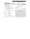
[0037] FIG. 1 shows the block diagram of the CO2 recycling apparatus of the present invention.
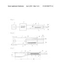
[0038] FIG. 2 shows the block diagram of the CO2 recycling apparatus of embodiment 1 (plan view).
[0039] FIG. 3 shows the block diagram of the CO2 recycling apparatus of embodiment 1 (front view).
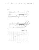
[0040] FIG. 4 shows the block diagram of the CO2 recycling apparatus of embodiment 2 (plan view).
[0041] FIG. 5 shows the block diagram of the CO2 recycling apparatus of embodiment 2 (front view).
[0042] FIG. 6 shows the graph showing correlation between input energy and CO2 decomposition rate.
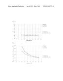
[0043] FIG. 7 shows the graph showing correlation between input energy and CO2 dissociation rate.
[0044] FIG. 8 shows the graph showing correlation between input energy and equipment efficiency.
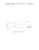
[0045] FIG. 9 shows the graph showing correlation between gas composition and CO2 decomposition rate.
BEST MODE FOR CARRYING OUT THE INVENTION
[0046] Embodiments of the present invention will be described in detail below with reference to the drawings. The present invention is not limited to the following embodiment and examples of shown in the figure, and the present invention can be variously changed in design.
[0047] FIG. 1 shows the block diagram of the CO2 recycling apparatus of the present invention. The present CO2 recycling apparatus has the microwave guide 1, microwave generator 2 and reaction tube 3 which is installed in microwave guide 1. The reaction tube 3 is composed of gas inlet tube 5 and vacuum evacuation tube 4, and the gas flow in the reaction tube is turned back at the point 8. Inside the gas inlet, ceramics heater 6 is equipped.
[0048] Microwave is resonated in the microwave guide 1 by putting on the microwave generator 2, microwave plasma 20 originates at the point 8 where the gas flow is turned back. Microwave generator 2 functions by the power supply 7. Power supply 7 is 100V table tap for general family use, for example. CO2 gas is introduced from outer part of microwave guide 1 to gas inlet 5, turned back at the position 8 in the reaction tube 3, and evacuated from vacuum evacuation tube 4 after passing the location of microwave plasma 20. By designing gas flow in tubes 5 and 4, the length of reaction tube is shortened, and consequently the apparatus becomes compact.
[0049] Ceramics heater is stored in the inner wall of gas inlet where the microwave guide surrounds, and is heated by the microwave irradiation. CO2 gas which flows in the gas inlet 5 is heated when it flows near the ceramics heater 6. Near the location of folding back point 8, multi-wall carbon nanotube, carbon onion or nano-carbons are synthesized. Multi-wall carbon nanotube, carbon onion and/or other nano-carbons are deposited on the inner wall of vacuum evacuation tube.
[0050] Because the ceramics heater 6 is heated by the irradiation of microwave generated from the microwave generator 2, additional heaters are unnecessary. Therefore, the total electric energy consumption is determined only by the one from the microwave generator 2, and consequently the electric energy consumption becomes small.
[0051] In the below enforced embodiments, the shapes of reaction tubes, the relation between energy consumption and the amount of synthesized carbon nanotube, carbon onion and nano-carbon, the amount of CO2 decomposition are made clear, and the effect of CO2 decomposition of the present apparatus is quantitatively explained.
Embodiment 1
[0052] Embodiment 1 shows the CO2 recycling apparatus with the U-shaped reaction tube. FIGS. 2 and 3 indicate horizontal and front views of the above CO2 recycling apparatus, respectively.
[0053] As shown in the horizontal view (FIG. 2), the microwave guide 1 is a rectangular box when viewed from vertical position, and the U-shaped tube 10 is inserted to the center of 1. As shown in the front view (FIG. 3), the height of microwave guide 1 at the opposite position to the location of U-shaped tube 10 is high (cross sectional area is large), and the cross sectional area becomes small near the location of 10. From the left-hand side to the center of FIG. 3, the height becomes small and is constant at the right-hand side. Here let h, A and B the height at left-hand side, the distance from the center to the left end, and the distance from the center to the right-hand end, respectively. A and B are almost the same, and actually about 189 mm. h is approximately 50 mm.
[0054] In FIGS. 2 and 3, the microwave generator is placed near the right-hand side of microwave guide 1, but not shown in the figures.
[0055] U-shaped tube 10 is placed inside of the microwave guide 1. The U-shaped tube is folded back near the center between gas inlet 5 and vacuum evacuation 4. Ceramics heater 6 is placed inside the gas inlet 5. At the both sides of ceramics heater 6, ceramics fibers are molded. The material of ceramics heater is silicon carbide (SiC).
[0056] At the position of folding back of the U-shaped tube 10, i.e., 8, microwave plasma generates. For adjusting the resonance and tuning the conditions of microwave plasma generation, microwave matching device 12 is fitted (see FIG. 3).
[0057] By the microwave plasma of CO2 gas, multi-wall carbon nanotube, carbon onion and/or nano-carbon are deposited on the inner wall of vacuum evacuation tube 4 of the U-shaped tube 10. These deposits are derived from the solidification of carbon (C) contained in the CO2 gas. Thus, the exhausted gas from the vacuum evacuation tube has less content of CO2 than the one introduced from gas inlet tube 5.
[0058] The reduction amount and the rate of reduction of CO2 are explained.
[0059] Table 1 tabulates the relation between electric power and the reduction rate of CO2, when CO2 was decomposed by microwave plasma CVD to deposit solid carbons on the inner wall of vacuum evacuation tube 4 of U-shaped tube 10. The introduced gases from gas inlet 5 of U-shaped tube 10 were 20 sccm of CO2 and 80 sccm of H2 (carrier gas).
TABLE-US-00001 TABLE 1 Input power [W] CO2 decomposition rate [%] 100 68.5 150 73.0 200 81.0 250 83.0 300 86.0 350 87.5 400 92.5
[0060] FIG. 6 indicates the plot of Table 1, i.e., the correlation between input energy and CO2 decomposition rate. It is seen that the CO2 decomposition rate is about 70% at the input energy of 100 W, and the decomposition rate becomes large as the input energy increases.
[0061] Here, it is noted that the energy required for totally decompose CO2 into C is 1597.9 [kJ].
CO2+526.1 [kJ]=CO+O
CO+1071.8 [kJ]=C+O
[0062] An introduction of 20 sccm CO2 means the CO2 flow with 20×10-3/22.4×1/60 (mol/s)=1.488×10-5 (mol/s). To decompose 20 sccm totally, 1.488×10⁻³ (mol/s)×1597.9 [kJ]=23.78×10⁻³ [kJ/s]=23.78 (W) is needed.
[0063] Let (the energy required for totally decomposing introduced CO2)×CO2 decomposition rate=A, A becomes 23.78 (W)×0.685=16.29 (W) when the input power and the decomposition rate are 100 (W) and 68.5%, respectively. The efficiency of apparatus is calculated by dividing A by the input energy, and becomes 16.29 (W)/100 (W)=0.1629, that is, 16.29%.
[0064] At 150 (W) input energy and 73.0% decomposition rate, A is 23.78 (W)×0.73=17.36 (W). The efficiency of apparatus is 17.36 (W)/150 (W)=0.1157, that is, 11.57%.
[0065] At 200 (W) input energy and 81.0% decomposition rate, A is 23.78 (W)×0.81=19.26 (W). The efficiency of apparatus is 19.26 (W)/200 (W)=0.0964, that is. 9.63%.
[0066] A and the efficiency of apparatus were calculated at the input energy of 250 (W), . . . , 400 (W), and tabulated in Table 2. FIG. 7 is the plot of Table 2, and indicates the correlation between input energy and A (=energy input to totally decompose the introduced CO2×CO2 decomposition rate). FIG. 8 is the plot of Table 2, and indicates the correlation between input energy and the efficiency of apparatus.
TABLE-US-00002 TABLE 2 Input CO2 decom- (Equipment power position rate (A) efficiency) [W] [%] [W] [%] 100 68.5 16.29 16.29 150 78.0 17.36 11.57 200 81.0 19.26 9.63 250 83.0 19.74 7.89 300 86.0 20.45 6.82 350 87.5 20.81 5.94 400 92.5 21.99 5.50
[0067] The maximum theoretical value in FIGS. 7 and 8 is explained. The maximum theoretical value means 100% decomposition of CO2, and let the maximum theoretical value A*, and the maximum theoretical value of apparatus efficiency*.
[0068] At the input energy of 100 (W), A*=23.78 (W)×1=28.78 (W). The apparatus efficiency* can be calculated by the ratio of the input power and A*, and 23.78 (W)/100 (W)=0.2378, that is, 23.78%.
[0069] Similarly, at the input energy of 150 (W), A*=23.78(W)×1=23.78 (W). The apparatus efficiency* is 23.78 (W)/150 (W)=0.1585, that is, 15.85%.
[0070] AT the input energy of 200 (W), A*=23.78 (W) x1=23.78 (W). The apparatus efficiency* is 23.78 (W)/200 (W)=0.1189, that is, 11.89%.
[0071] FIG. 9 shows the correlation between gas composition and the rate of CO2 decomposition. As the CO2 density in the introduced gas increases, the CO2 decomposition rate decreases. Clearly from the present experimental results, the decomposition rate of U-shaped tube is higher than that of T-shaped tube.
[0072] The CO2 recycling system uses multiple numbers of CO2 recycling apparatus, and in this case the vacuum evacuation part of one apparatus is connected to the gas inlet part of the other apparatus. By connecting multiple CO2 recycling apparatus, the reduction rate of CO2 becomes much higher.
[0073] The present invention aims the synthesis of nano-carbons, and contributes to the effective use and solidifying methods of CO2 by depositing high value-added nano-carbons. The amount of solidifying CO2 as segregated amorphous fibers is explained.
[0074] m0 (g), the mass of C in the introduced CO2 gas, is expressed by equation (1), when the mass flow of CO2 is Q (sccm) and the time of plasma CVD is t (min).
[ Equation 1 ] m 0 = Q × 10 - 3 × t 22.4 × 12 ( 1 ) ##EQU00001##
[0075] When the CO2 flow is 20 (sccm) and time is 10 minutes, m0 becomes 0.107 (g) from eq. (1). In addition, when 1 (nm) is the length of amorphous fiber, D(nm) the diameter, dc(μm-2) the segregated density, S(cm2) the surface area of substrate, and dc(g/cm3) the density of amorphous carbon, m(g), the mass of solidified C as the segregated fiber, is written by the equation (2).
[ Equation 2 ] m = 1 4 π ( D × 10 - 7 ) 2 × l × 10 - 7 × d c × d d 10 8 × S ( 2 ) ##EQU00002##
[0076] The calculation were carried out by the following conditions: the length l=900 (nm), the diameter D=45 (nm), segregation density dd=20 (μm-2), area of substrate S=0.5 (cm2). The value of density of amorphous carbon reported till now cannot be applied to dd. Theoretical estimation of dd also is difficult, since the ratio of sp2 and spa as well as the content of hydrogen is not known. From these reasons, the actual density was estimated at dd=1.0˜3.0 (g/cm3), which are a little bit smaller than the density of diamond, 3.52 (g/cm3). The calculation of eq. (2) resulted in m=1.43˜4.29×10⁻⁶ (g). The ratio of solidified carbon in the form of segregated fibers is expressed by the equation (3).
[ Equation 3 ] S = m m 0 ( 3 ) ##EQU00003##
[0077] The calculation of eq. (3) resulted in s=1.34˜4.00×10⁻⁵. This result is a rough calculation, and the values are not quite precise. However, the order of the ratio s will not be far from the real value. It is important to increase the value of s, namely, to synthesize as many as amorphous fibers. It is anticipated to increase the amount of synthesized amorphous fibers by increasing the area of substrate and by increasing the amount of gas flow.
Embodiment 2
[0078] Embodiment 2 was carried out by using two CO2 recycling apparatus with U-shaped reaction tubes (two series configuration). The vacuum evacuation part 4 of the first apparatus was connected to the gas inlet 5 of the next apparatus. CO2 gas introduced from the gas inlet 5 of the first apparatus is decomposed and reduced by the microwave plasma generated near the folding point 8 of the first apparatus and evacuated from the vacuum evacuation part 4. The vacuum evacuation part 4 of the first apparatus is connected to the gas inlet 5, and consequently the gas introduced from the gas inlet of the next apparatus has somewhat been decomposed and reduced. The microwave plasma near the folding point 8 of the reaction tube, the second decomposition and reduction of CO2 occurs.
[0079] Table 3 compares the experimental results of CO2 decomposition (reduction) rates obtained from the single CO2 recycling apparatus and from the one that has two CO2 recycling apparatus with U-shaped reaction tube. The introduced gas was 20 sccm CO2 and 80 sccm H2 as a carried gas. The input power was constant at 100 (W) for all the U-shaped reaction tube. In the case of 2 CO2 recycling apparatus aligned in series, the input power of 100 (W) is applied to the both of U-shaped reaction tubes. For single CO2 recycling apparatus, the reduction rate was 68.5%, while for the two CO2 recycling apparatus connected in series, the reduction rate was 79.5%. From these results, it is clear that CO2 recycling apparatus connected in series decomposes larger amount of CO2 than the single one does.
TABLE-US-00003 TABLE 3 Introduced Total gas CO2 Measurement result Reduction H2 CO2 flow concentration Before After rate CO (sccm) (sccm) (sccm) (%) plasma plasma (%) (%) 1-stage U-shaped tube (1 station) 80 20 100 20 20 6.3 68.5 14 2-stage U-shaped tube (2 stations) 80 20 100 20 19.5 4 79.5 21
Other embodiments
[0080] (1) In the above stated embodiments, the U-shaped tube was used as a reaction tube. However, the reaction tube with different diameters is also applicable. In this case, the tube with smaller diameter is connected to the gas inlet, while the one with larger diameter to the vacuum evacuation (see FIGS. 4 and 5). It is advantageous to increase the path of gas flow. Therefore, spiral shaped tube or zigzag tube works effectively as well.
[0081] (2) In the above stated embodiments, the microwave guide was used. However, coaxial microwave cable is also applicable. The coaxial microwave cable can be placed near the folding back point of reaction tube.
INDUSTRIAL APPLICABILITY
[0082] The present invention works effectively, as CO2 recycling apparatus, against CO2 exhausted from automobiles, ships, public buildings, commercial centers and ordinary families.
DESCRIPTION OF SYMBOLS
[0083] 1 Microwave guide; 2 Microwave generator; 3 Reaction tube; 4 Vacuum evacuation tube; 5 Gas inlet; 6 Ceramics heater; 7 Power supply; 8 Folding back point; 10 U-shaped tube; 11 Two-layer tube; 12 Microwave matching device (Stub); 14 Flange; 16 Plate; 17 Stopper; 18 Supporting member; 20 Microwave plasma
User Contributions:
Comment about this patent or add new information about this topic:
| People who visited this patent also read: | |
| Patent application number | Title |
|---|---|
| 20200330285 | AREA MANAGEMENT OF TISSUE SITES ON ARTICULATING JOINTS |
| 20200330284 | DRESSING WITH CONTRACTING LAYER FOR LINEAR TISSUE SITES |
| 20200330283 | Tissue Treatment Systems And Methods Having A Porous Substrate With A Compressed Region And An Expanded Region |
| 20200330282 | EARPLUG AND PUMPING SYSTEMS |
| 20200330281 | EXCIMER LASER FIBER ILLUMINATION |
Images included with this patent application:
 |  |
 |  |
 |
| Similar patent applications: | |
| Date | Title |
|---|---|
| 2015-04-16 | Powder coating system |
| 2014-10-09 | Vapor delivery system |
| 2015-05-21 | Resin container coating device |
| 2011-12-22 | Apparatus and method for treating an object |
| 2011-12-29 | Coating system |
| New patent applications in this class: | |
| Date | Title |
|---|---|
| 2016-01-28 | Film-forming device |
| 2014-10-30 | Chemical vapor deposition with energy input |
| 2014-08-21 | Microwave plasma reactor for manufacturing synthetic diamond material |
| 2014-02-20 | Microwave plasma reactor for manufacturing synthetic diamond material |
| 2013-08-29 | Method and apparatus for manufacturing semiconductor device |
| Top Inventors for class "Coating apparatus" | |
| Rank | Inventor's name |
|---|---|
| 1 | Shao-Kai Pei |
| 2 | John M. White |
| 3 | Soo Young Choi |
| 4 | David K. Carlson |
| 5 | Robin L. Tiner |