Patent application title: Device for Tamping, Smoothing or Impressing Poured Concrete
Inventors:
Jerome V. Garceau (Warrenville, IL, US)
IPC8 Class: AE01C1948FI
USPC Class:
404 93
Class name: Road structure, process, or apparatus apparatus with surface marking (or grooving)
Publication date: 2014-09-18
Patent application number: 20140270958
Abstract:
A hand held device tamping, smoothing or impressing a specifically
desired pattern or form onto freshly poured concrete, such as on a
sidewalk or another selected surface. The hand held device including a
base and a handle, the base having a non-circular shaped receiver which
matches with a non-circular cross-section portion of the handle to
provide a rigid connection between the handle and the base and a simple
means for aligning a hole in the handle with a hole in the base for a pin
to pass through.Claims:
1. A device for smoothing or impressing a pattern onto freshly poured
concrete, the device comprising: a handle with a polygonal terminal end;
a base including a platform and a collar extending from a top surface of
the platform; and a receiver positioned within a portion of the collar
for receiving the handle, the receiver having a polygonal opening that
matches the polygonal terminal end of the handle.
2. The device of claim 1, wherein the base is manufactured of an elastomeric material.
3. The device of claim 1, wherein the polygonal opening comprises a square opening.
4. The device of claim 1, wherein the base further comprises a collar hole and the handle further comprise a handle hole in the handle terminal end and a pin passes through the collar hole and the handle hole to secure the base to the handle.
5. The device of claim 1, wherein the base further comprises one of a smooth surface and a textured surface on a bottom surface of the base.
6. A device for smoothing or impressing a pattern onto freshly poured concrete, the device comprising: a handle with a terminal end which comprises a non-circular shaped cross-section; a base including a platform and a collar extending from a top surface of the platform; and a receiver positioned within a portion of the collar for receiving the terminal end of the handle, the receiver comprising a void in the collar, the void having a non-circular shaped cross-section that matches the terminal end of the handle.
7. The device of claim 6, wherein the base is manufactured of an elastomeric material.
8. The device of claim 6, wherein the receiver comprises a square opening and the terminal end comprises a square cross-section.
9. The device of claim 6, wherein the base further comprises a collar hole and the handle further comprise a handle hole in the handle terminal end and a pin passes through the collar hole and the handle hole to secure the base to the handle.
10. The device of claim 6, wherein the base further comprises one of a smooth surface and a textured surface on a bottom surface of the base.
Description:
BACKGROUND OF THE INVENTION
[0001] 1. Field of the Invention
[0002] This invention relates generally to hand held devices for tamping, smoothing or impressing a specifically desired pattern or form onto recently poured concrete which has not set or cured, such as a sidewalk or another selected surface. The devices of this invention are commonly known as tampers, pounders or stampers.
[0003] 2. BACKGROUND OF THE INVENTION
[0004] U.S. Pat. No. 7,387,466 discloses a known device for imprinting patterns on concrete. The device includes a base with a cylindrical recess for receiving a cylindrical handle. The cylindrical handle is secured to the base with a pin which extends through the cylindrical recess and the cylindrical handle. One shortcoming of the '466 Patent is that it can be difficult to align a hole in the cylindrical recess with a hole the cylindrical handle to pass the pin through both holes.
SUMMARY OF THE INVENTION
[0005] A general object of the invention is to provide an improved device for tamping, smoothing or impressing a specifically desired pattern or form onto freshly poured concrete, such as on a sidewalk or another selected surface.
[0006] The improved device of this invention includes a base that is attached and secured to a handle with a pin. The base includes an opening with a non-circular cross-section for receiving the handle. The handle includes a non-circular shaped end that corresponds to the non-circular cross-section of the opening. The improved device provides a rigid connection between the handle and the base and a simple means for aligning a hole in the handle with a hole in the base so that the pin can easily pass through both holes.
BRIEF DESCRIPTION OF THE DRAWINGS
[0007] These and other objects and features of this invention will be better understood from the following detailed description taken in conjunction with the drawings, wherein:
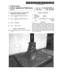
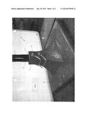
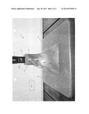
[0008] FIG. 1 is a perspective angled side view of a tamper, in accordance with one embodiment of the invention, for smoothing or impressing a pattern onto freshly poured concrete; and
[0009] FIG. 2 is a perspective side view of the tamper shown in FIG. 1.
DETAILED DESCRIPTION OF THE INVENTION
[0010] The present invention provides an improved device for smoothing or impressing a specifically desired pattern or form onto uncured concrete such as, but not limited to sidewalks, driveways, streets, curbs, concrete floors or other surfaces.
[0011] FIGS. 1 and 2 illustrate a tamper 10 according to one embodiment of this invention. The tamper 10 preferably includes a base 12 and a handle 14 that are secured to each other with a pin 16 which passes through a hole in each of the base 12 and the handle 14. In the embodiment of FIGS. 1 and 2, the tamper 10 includes a plurality of pins 16.
[0012] The base 12 of this invention is preferably manufactured of an elastomeric material including, but not limited to, Shore A urethane (such as Shore A urethane with a durometer in the range of 25 to 100), Shore D urethane, silicone and/or latex. The elastomeric material reduces the physical impact on a user tamping freshly poured concrete. Alternatively, the base 12 can be made of any other material useful for tamping freshly poured concrete, such as, but not limited to, metal or composite materials. Further, those skilled in the art and guided by the teachings herein provided will understand and appreciate that the base 12 can be desirably fabricated or manufactured by various techniques including, for example, injection molding. In another alternative embodiment, the base 12 may be manufactured with a core material which is a different material than a surrounding material, for example, but not limited to, a metal core surrounded by an elastomeric material.
[0013] The base 12 includes a platform 18 with a collar 20 extending from an upper surface of the platform 18. In this embodiment, the platform 18 comprises a square or rectangular shape however, the platform 18 may comprise any shape. In an embodiment of this invention, a lower surface of the platform 18 includes a textured surface for impressing a pattern or texture onto recently poured concrete which has not set. Such as a pattern in the form or appearance of brick, stone, rock, wood or other material as may be desired in a specific or particular application. In an alternative embodiment, the lower surface of the platform 18 includes a smooth surface for tamping and/or smoothing a surface of recently poured concrete which has not set.
[0014] The collar 20 is preferably integrally formed with and extends from the upper surface of platform 18. In this embodiment, the collar 20 comprise four surfaces that extend from the platform 18 and gradually narrow, in a pyramid-like fashion near the bottom, and transition into generally vertical surfaces that end at a generally flat top surface. However, the collar 20 is not limited to this shape and may comprise any shape capable of receiving a portion of the handle 14. As shown in the figures, the collar 20 includes a receiver 22 comprising an opening in the flat top surface and a void extending into the collar 20 for receiving a portion of the handle 14. In a preferred embodiment, the receiver 22 comprises a polygon-shaped cross-section that matches with an insert portion of the handle 14 allowing for easy alignment of holes for receiving the pin 16. In the embodiment of FIGS. 1 and 2, the receiver 22 comprises a square-shaped opening however, the receiver 22 may comprise any non-circular shape including, but not limited to, a triangular shape, a rectangular shape, an elliptical shape, a star shape, a pentagon shape and a hexagon shape.
[0015] As shown in FIGS. 1 and 2, the handle 14 includes a polygon-shaped handle terminal end 24 that is designed to match the polygon-shaped receiver 22 of the base 12. In this embodiment, the handle 14 includes an upper cylindrical portion that transitions into a polygon-shaped handle terminal end 24. In an alternative embodiment, the handle 14 may comprise a uniform polygon-shape along an entire length of the handle without a transition portion. The polygon-shaped handle terminal end 24 of FIGS. 1 and 2 comprises a square shape however, the handle insert 24 may comprise any non-circular shape including, but not limited to, a triangular shape, a rectangular shape, an elliptical shape, a star shape, a pentagon shape and a hexagon shape.
[0016] The collar portion 20 and the handle terminal end 24 each include holes which must be aligned so that the pin 16 can pass through both holes to secure the base to the handle. The polygon-shaped receiver 22 and the matching polygon-shaped handle terminal end 24 simplifies the alignment process by restricting the number of ways that the handle terminal end 24 can fit into the receiver 22.
[0017] In an alternative embodiment of this invention, the tamper 10 may be used with a mat, not shown, that includes a surface with a textured or smooth surface for impressing a pattern or texture onto recently poured concrete or for smoothing recently poured concrete. The mat may be placed on uncured concrete and the tamper 10 may be used to press the mat into the uncured concrete to create a surface impression in the concrete.
[0018] The invention illustratively disclosed herein suitably may be practiced in the absence of any element, part, step, component, or ingredient which is not specifically disclosed herein.
[0019] While in the foregoing detailed description this invention has been described in relation to certain preferred embodiments thereof, and many details have been set forth for purposes of illustration, it will be apparent to those skilled in the art that the invention is susceptible to additional embodiments and that certain of the details described herein can be varied considerably without departing from the basic principles of the invention.
User Contributions:
Comment about this patent or add new information about this topic:
Images included with this patent application:
 |  |
 |
| Similar patent applications: | |
| Date | Title |
|---|---|
| 2015-01-08 | End treatments and transitions for water-ballasted protection barrier arrays |
| 2015-01-15 | Autoadaptive engine idle speed control |
| 2014-12-18 | Compactor roller for a soil compactor |
| 2015-01-08 | Cover for a concrete parking block |
| 2015-01-15 | Integrated security barrier control system |
| New patent applications in this class: | |
| Date | Title |
|---|---|
| 2015-11-19 | Modular screed box |
| 2014-09-18 | Imprint roller for stamping concrete |
| 2014-09-18 | Grinding attachment |
| 2014-08-07 | Method and apparatus for forming and applying retroreflective pavement markings |
| 2014-02-20 | Mechanized asphalt comb |
| New patent applications from these inventors: | |
| Date | Title |
|---|---|
| 2014-06-12 | Pattern impressing via a roller element |
| Top Inventors for class "Road structure, process, or apparatus" | |
| Rank | Inventor's name |
|---|---|
| 1 | Günter Hähn |
| 2 | Martin Buschmann |
| 3 | Cyrus Barimani |
| 4 | Ralf Weiser |
| 5 | Ronald D. Shaw |