Patent application title: Vacuum Tank Trailer Discharge Port
Inventors:
Yuval Doron (College Station, TX, US)
Andrew T. Duggleby (College Station, TX, US)
IPC8 Class: AB60P322FI
USPC Class:
137577
Class name: Fluid handling systems tank with movable or adjustable outlet or overflow pipe
Publication date: 2014-09-11
Patent application number: 20140251471
Abstract:
Disclosed is a port system for facilitating mixed solid/liquid content
discharge from a portable tank especially vacuum tank trailer, discharge
system. The system provides an enlarged sloped tank outlet system that
overcomes the deficiencies of convention systems.Claims:
1. A tank discharge system comprising a main conduit of nominal 6 to 10
inch diameter that attaches to the underside of an elongated circular
tank, the conduit having two conjoined members, the first member
configured to mate to the bottom of an elongated circular tank and the
second to be parallel to the long plane of the tank.
2. The discharge system of claim 1 comprising at least one additional conduit attached beside and at angle to the main conduit.
3. The system of claim 1 wherein the main conduit is nominal 8 inch diameter.
4. The system of claim 2 wherein the additional conduit is nominal 2 to 6 inch diameter.
5. The system of claim 1 wherein the tank is a vacuum tank trailer.
6. The system of claim 1 wherein there are nozzle(s) pointing downward in the drain member(s) and a conduit connection (such as a hose connection) to allow water to be sprayed into the member to assist in draining and flushing the drain member.
7. The system of claim 1 wherein each member have half flanges, attached to allow valves to be attached.
8. A trailer system comprising a trailer having disposed thereon a tank discharge system comprising a main conduit of nominal 6 to 10 inch diameter that attaches to the underside of an elongated circular tank, the conduit having two conjoined members, the first member configured to mate to the bottom of an elongated circular tank and the second to be parallel to the long plane of the tank.
9. The trailer system of claim 8 wherein discharge system comprises at least one additional conduit attached beside and at angle to the main conduit.
10. The trailer system of claim 8 wherein there are nozzle(s) pointing downward in the drain member(s) and a conduit connection (such as a hose connection) to allow water to be sprayed into the member to assist in draining and flushing the drain member.
Description:
CROSS REFERENCE TO RELATED APPLICATIONS
[0001] This application claims benefit of Provisional Application Ser. No. 61/775,349 filed Mar. 8, 2013. The contents and disclosures of the application is incorporated herein by reference in its entirety for all purposes.
BACKGROUND
[0002] 1. Field
[0003] Portable tanks, especially vacuum tank trailer, discharge system. A port discharge system for facilitating mixed solid/liquid content discharge from a portable tank.
[0004] 2. Background
[0005] Vacuum tank trailers (and trucks) are increasing engaged in uses in hauling liquids contents with significant solid content. Such trailer are in heavy use in oil and gas operations where high solid content materials are transported to and from well sites. Liquid with solid contents (mud and the like) are often difficult to remove from the tank.
[0006] It is customary to discharge tank contents through one or more nominal 4 inch pipe outlets located at the rear bottom of the tank. Generally the contents must be flushed out by water hose from the top opening of the tank. This procedure is time consuming and therefore expensive since it ties up the tank and driver for longer than necessary.
[0007] Some trailers tilt as in a dump truck to aid in discharge of the solids containing liquid but they are considerably more expensive than non-tilting tanks.
SUMMARY
[0008] The present invention provides an enlarged sloped tank outlet system that overcomes the deficiencies of convention systems.
DESCRIPTION OF THE FIGURES
[0009] The Figures represent embodiments of the invention and are not intended to be limiting of the scope of the invention.
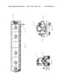
[0010] FIG. 1a is a top view of a vacuum tank trailer showing the system of an embodiment of the invention located at the rear bottom of the trailer.
[0011] FIG. 1b is a rear view of a vacuum tank trailer showing the system of an embodiment of the invention located at the rear bottom of the trailer.
[0012] FIG. 1c is an enlarged rear view of a vacuum tank trailer showing the system of an embodiment of the invention located at the rear bottom of the trailer.
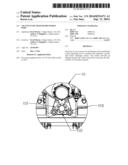
[0013] FIG. 2a is an end view of the system of an embodiment of the invention.
[0014] FIG. 2b is a top view of the system of an embodiment of the invention.
[0015] FIG. 2c is perspective isometric view of the system of an embodiment of the invention.
[0016] FIG. 2d is a side view of the system of an embodiment of the invention.
DETAILED DESCRIPTION
[0017] The tank discharge system of embodiments of the invention comprises a conduit of 6 to 10 inch diameter that attaches to the underside of an elongated circular tank, the conduit having two conjoined members, and the first member configured to mate to the bottom of a tank and the second to be substantially parallel to the long plane of the tank.
[0018] An exemplary embodiment of the invention is illustrated in the drawings. FIG. 1a is the top side view and FIG. 1b is a rear view of a tank trailer 10, showing the placement of member 102 of an embodiment of the invention. FIG. 1c is an enlarged section of the rear view of tank 10 showing component 102, 101, and 103 of the system.
[0019] The FIGS. 2a-2d show details of the conduit of an embodiment of the invention. Referring to FIGS. 2a-2d, the principal member 102 comprises two components, one tilted from the vertical that is attached to the underside of the tank at 106, the other configured to be substantially horizontal to the ground (and the long plane of the tank) when the system is attached Sand the tank level). Attachment to the tank is preferably by welding if the system and tank is metal--adhesive if the tank is polymer materials (such as fiberglass). Extending at an angle from the principal member is, in one embodiment, side arms 101 and 105. These are generally 2 to 6 inch nominal diameter conduit. They may be used when the main drain 102 is not needed (as when the liquid content is of low solid content and/or when it is necessary to connect to an existing drain conduit of a smaller diameter than the main drain member 102. Either one or more auxiliary drains (as shown) may be attached. Generally, each member, 102, 101 and 103 will have half flanges, 121,122 and 123 attached to allow valves to be attached. Other suitable connection means may also be used.
[0020] There may also be flush ports inserted at several points in the main drain member, for example, at points 115, 116 and 117. These ports can have a nozzle pointing downward in the drain member and a conduit connection (such as a hose connection) to allow water to be sprayed into the member to assist in draining and flushing the drain member.
[0021] The embodiment shown is attached at the rear of an elongate tank. The system may also be attached to the side of the tank as necessary, as for example, if the tank is compartmented and a drain or drains are needed along the sides of the tank.
[0022] In this specification, the invention has been described with reference to specific embodiments thereof. It will, however, be evident that various modifications and changes can be made thereto without departing from the broader spirit and scope of the invention as set forth in the appended claims. The specification is, accordingly, to be regarded in an illustrative rather than a restrictive sense. Therefore, the scope of the invention should be limited only by the appended claims.
User Contributions:
Comment about this patent or add new information about this topic:
Images included with this patent application:
 |  |
 |
| Similar patent applications: | |
| Date | Title |
|---|---|
| 2014-09-18 | Septic system with overflow discharge system |
| 2014-09-18 | High thermal transfer flow-through heat exchanger |
| 2014-09-18 | Self-draining ullage fuel tank systems and related methods |
| 2014-09-18 | Water treatment system tank selector valve assembly |
| 2014-09-18 | Fluid path set with turbulent mixing chamber, backflow compensator |
| New patent applications in this class: | |
| Date | Title |
|---|---|
| 2015-12-03 | Liquid supplying device and photoresist coating equipment |
| 2009-04-09 | System for dispensing and recovering liquids and device comprising same |
| New patent applications from these inventors: | |
| Date | Title |
|---|---|
| 2022-09-08 | Side mounted air supply for wheel lift independent of vehicle air brake |
| Top Inventors for class "Fluid handling" | |
| Rank | Inventor's name |
|---|---|
| 1 | Nobukazu Ikeda |
| 2 | Kouji Nishino |
| 3 | Ryousuke Dohi |
| 4 | Kevin T. Peel |
| 5 | Huasong Zhou |