Patent application title: EXHAUST GAS PURIFICATION SYSTEM OF VEHICLE
Inventors:
Choong Il Kwon (Gunpo-Si, KR)
Assignees:
Kia Motors Corporation
Hyundai Motor Company
IPC8 Class: AF01N328FI
USPC Class:
422170
Class name: Waste gas purifier including means providing sequential purification stages plural chemical reaction stages
Publication date: 2014-05-15
Patent application number: 20140134062
Abstract:
An exhaust gas purification system for a vehicle may include a diesel
oxidation catalyst (DOC) unit installed at an exhaust pipe, and a
composite catalyst unit installed at the exhaust pipe at a rear end of
the DOC unit and including a selective catalyst reduction (SCR) catalyst
and an oxidation catalyst formed at a diesel particulate matter filter
(DPF). The exhaust gas purification system may also include an injector
provided between the DOC unit and the composite catalyst unit and
configured to inject a reducing agent into the exhaust pipe. The SCR
catalyst may be formed at an exhaust gas inlet side of the DPF and the
oxidation catalyst may be formed at an exhaust gas outlet side of the
DPF.Claims:
1. An exhaust gas purification system for a vehicle, comprising: a diesel
oxidation catalyst (DOC) unit installed at an exhaust pipe; a composite
catalyst unit installed at the exhaust pipe at a rear end of the DOC unit
and including a selective catalyst reduction (SCR) catalyst and an
oxidation catalyst formed at a diesel particulate matter filter (DPF);
and an injector provided between the DOC unit and the composite catalyst
unit and configured to inject a reducing agent into the exhaust pipe,
wherein the SCR catalyst is formed at an exhaust gas inlet side of the
DPF and the oxidation catalyst is formed at an exhaust gas outlet side of
the DPF.
2. The exhaust gas purification system of claim 1, wherein a catalyst non-coating region is present between the inlet side and the outlet side of the DPF.
3. The exhaust gas purification system of claim 1, wherein the SCR catalyst comprises a material selected from Cu or Fe based zeolite and/or vanadium based materials.
4. The exhaust gas purification system of claim 1, wherein the oxidation catalyst comprises a noble metal catalyst selected from a group consisting of Pt, Pd, and Rh.
5. The exhaust gas purification system of claim 1, wherein the composite catalyst unit includes a SCR on DPF (SDPF).
6. An exhaust gas purification system comprising: a DOC unit installed at an exhaust pipe; and a composite catalyst unit installed at the exhaust pipe at a rear end of the DOC unit and including a SCR catalyst and an oxidation catalyst formed at a DPF, wherein the composite catalyst unit includes a catalyst non-coating region provided between a coating region of the SCR catalyst and a coating region of the oxidation catalyst.
7. The exhaust gas purification system of claim 6, wherein the DPF includes a cell passage having a zigzag form.
8. The exhaust gas purification system of claim 7, wherein the SCR catalyst is coated on an exhaust gas inlet side of the cell passage, and the oxidation catalyst is coated on an exhaust gas outlet side of the cell passage.
Description:
CROSS-REFERENCE TO RELATED APPLICATION
[0001] The present application claims priority of Korean Patent Application Number 10-2012-0127577 filed Nov. 12, 2012, the entire contents of which application are incorporated herein for all purposes by this reference.
BACKGROUND OF INVENTION
[0002] 1. Field of Invention
[0003] The present invention relates to an exhaust system for a vehicle, and more particularly, to an exhaust gas purification system capable of reducing pollutants in exhaust gas.
[0004] 2. Description of Related Art
[0005] In general, an exhaust system of an engine includes an exhaust gas aftertreatment apparatus such as a DOC (diesel oxidation catalyst), a DPF (diesel particulate matter filter), a SCR (selective catalyst reduction), a LNT (lean NOx trap), and the like in order to reduce carbon monoxide (CO), hydrocarbon (HC), particulate matters, nitrogen oxide (NOx), and the like, which are pollutants contained in exhaust gas.
[0006] The DOC may oxidize all hydrocarbons and carbon monoxide in the exhaust gas, and oxidize nitrogen monoxide to nitrogen dioxide. The DPF may trap particulate matters in the exhaust gas, and purify the particulate matters through a chemical conversion process.
[0007] Further, the SCR converts a reducing agent (urea), which is injected in a stream direction of the exhaust gas by an injector, into ammonia (NH3) using heat of the exhaust gas, and reduces nitrogen oxide to nitrogen gas (N2) and water (H2O) by a catalyst reaction between nitrogen oxide in the exhaust gas and ammonia by an SCR catalyst.
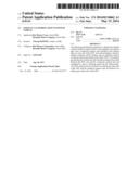
[0008] As an example of an exhaust gas purification system of the related art, which adopts the DOC, the DPF, and the SCR that are described above, the DOC 2 and the DPF 3 are mounted on the path of an exhaust pipe 1 in a stream direction of exhaust gas, and the SCR 4 is mounted at a rear end of the DPF 3, as illustrated in FIG. 1.
[0009] Here, a reducing agent slip catalyst 5 is installed at a rear end of the SCR 4 for removing a reducing agent slip which occurs on the SCR catalyst. In addition, a mix region where a reducing agent and the exhaust gas are mixed is provided between a rear end of the DPF 3 and a front end of the SCR 4, and an injector 7, which injects the reducing agent into the exhaust pipe 1, is mounted in the mix region.
[0010] In the aforementioned exhaust gas purification system, because the SCR 4 has a comparatively large volume in order to achieve sufficient purification efficiency of the nitrogen oxide in the exhaust gas, the SCR 4 is mounted at an under floor of a vehicle.
[0011] Therefore, since the SCR 4 is at the under floor of the vehicle in the related art, nitrogen oxide purification performance of the SCR catalyst may deteriorate as a temperature of the exhaust gas is lowered, and fuel efficiency may deteriorate as a weight of the vehicle is additionally increased.
[0012] Moreover, in the related art, since the SCR 4 having a comparatively large volume is provided and the reducing agent slip catalyst 5 is installed at the rear end of the SCR 4, production costs may be increased to manufacture a separate carrier and canning, which correspond to the SCR 4 and the reducing agent slip catalyst 5.
[0013] The information disclosed in this Background section is only for enhancement of understanding of the general background of the invention and should not be taken as an acknowledgement or any form of suggestion that this information forms the prior art already known to a person skilled in the art.
SUMMARY OF INVENTION
[0014] The present invention has been made in an effort to provide an exhaust gas purification system for a vehicle, capable of further improving purification performance of exhaust gas and reducing manufacturing costs with a simple configuration.
[0015] Various aspects of the present invention provide an exhaust gas purification system for a vehicle including: (i) a diesel oxidation catalyst (DOC) unit installed at an exhaust pipe, and (ii) a composite catalyst unit installed at the exhaust pipe at a rear end of the DOC unit and including a selective catalyst reduction (SCR) catalyst and an oxidation catalyst formed at a diesel particulate matter filter (DPP). In addition, the exhaust gas purification system for a vehicle may further include an injector provided between the DOC unit and the composite catalyst unit and configured to inject a reducing agent into the exhaust pipe.
[0016] In the exhaust gas purification system for a vehicle according to the present invention, the SCR catalyst may be formed at an exhaust gas inlet side of the DPF and the oxidation catalyst may be formed at an exhaust gas outlet side of the DPF. A catalyst non-coating region may be present between the inlet side and the outlet side of the DPF. The SCR catalyst may comprise a material selected from Cu or Fe based zeolite and/or vanadium based materials. The oxidation catalyst may comprise a noble metal catalyst selected from a group consisting of Pt, Pd, and Rh. The composite catalyst unit may include a SCR on DPF (SDPF).
[0017] Various other aspects of the present invention provide an exhaust gas purification system including: (i) a DOC unit installed at an exhaust pipe, and (ii) a composite catalyst unit installed at the exhaust pipe at a rear end of the DOC unit and including a SCR catalyst and an oxidation catalyst formed at a DPF, in which the composite catalyst unit may include a catalyst non-coating region provided between a coating region of the SCR catalyst and a coating region of the oxidation catalyst.
[0018] In addition, in the exhaust gas purification system for a vehicle according to the present invention, the DPF may include a cell passage having a zigzag form. The SCR catalyst may be coated on an exhaust gas inlet side of the cell passage. The oxidation catalyst may be coated on an exhaust gas outlet side of the cell passage.
[0019] In the exhaust gas purification system according to the present invention, because the composite catalyst unit is provided in which the SCR catalyst is formed at the inlet side of the cell passage of the DPF, and the oxidation catalyst is formed at the outlet side of the cell passage, an SCR having a large volume in the related art may be removed or eliminated.
[0020] In addition, in the exhaust gas purification system according to the present invention, because the oxidation catalyst is formed at the outlet side of the cell passage in the DPF of the composite catalyst unit, an amount of slip of the reducing agent, which is discharged without being reacted at the SCR catalyst, may be reduced, and CO, HC, or the like, which is generated by combustion of soot when the DPF is regenerated, may be purified while being oxidized.
[0021] In addition, in the exhaust gas purification system according to the present invention, because slip of the reducing agent, which is not reacted at the SCR catalyst, may be removed by the oxidation catalyst of the composite catalyst unit, a reducing agent slip catalyst of the related art may be removed or eliminated.
[0022] Accordingly, in the exhaust gas purification system according to the present invention, costs for manufacturing an SCR and a reducing agent slip catalyst may be reduced as an SCR and a reducing agent slip catalyst of the related art may be removed, and fuel efficiency may be improved as a weight of a vehicle is reduced.
[0023] In addition, in the exhaust gas purification system according to the present invention, as the SCR catalyst is installed to be closer to an engine in comparison with a case in which an SCR catalyst is installed at a rear end of the DPF, that is, the under floor of a vehicle, an exhaust gas temperature is formed to be higher than that of the related art, and as a result, purification efficiency of NOx may be improved.
[0024] Moreover, in the exhaust gas purification system according to the present invention, because the catalyst non-coating region is formed in order to prevent the SCR catalyst and the oxidation catalyst from being overlapped at the DPF of the composite catalyst unit, the SCR catalyst may perform its original function without degrading nitrogen oxide purification efficiency, and purification performance of nitrogen oxide may be improved to a level equal to or higher than the same level.
[0025] The methods and apparatuses of the present invention have other features and advantages which will be apparent from or are set forth in more detail in the accompanying drawings, which are incorporated herein, and the following Detailed Description, which together serve to explain certain principles of the present invention.
BRIEF DESCRIPTION OF THE DRAWINGS
[0026] FIG. 1 is a block diagram schematically illustrating an exhaust gas purification system for a vehicle according to the related art.
[0027] FIG. 2 is a block diagram schematically illustrating an exemplary exhaust gas purification system for a vehicle according to the present invention.
[0028] FIG. 3 is a cross-sectional view schematically illustrating an exemplary composite catalyst unit applied to an exhaust gas purification system for a vehicle according to the present invention.
[0029] FIG. 4 is a graph for explaining an operational effect of an exemplary exhaust gas purification system for a vehicle according to the present invention.
DETAILED DESCRIPTION
[0030] Reference will now be made in detail to various embodiments of the present invention(s), examples of which are illustrated in the accompanying drawings and described below. While the invention(s) will be described in conjunction with exemplary embodiments, it will be understood that present description is not intended to limit the invention(s) to those exemplary embodiments. On the contrary, the invention(s) is/are intended to cover not only the exemplary embodiments, but also various alternatives, modifications, equivalents and other embodiments, which may be included within the spirit and scope of the invention as defined by the appended claims.
[0031] To clearly describe the present invention, parts that are irrelevant to the description are omitted. Like numerals refer to like or similar constituent elements throughout the specification. The size and the thickness of each component illustrated in the drawings are illustrated in the drawings for better understanding and ease of description, but the present invention is not limited to the illustration. In the drawings, the thicknesses of various portions and regions are enlarged for clarity.
[0032] Further, in the following detailed description, names of constituent elements, which are in the same relationship, are divided into "the first", "the second", and the like, but the present invention is not limited to the order in the following description. In the specification, unless explicitly described to the contrary, the word "comprise" and variations such as "comprises" or "comprising", will be understood to imply the inclusion of stated elements but not the exclusion of any other elements. In addition, the terminologies such as " . . . unit", " . . . means", " . . . part", or " . . . member", which are disclosed in the specification, refer to a unit of an inclusive constituent which performs at least one of the functions or operations.
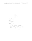
[0033] FIG. 2 is a block diagram schematically illustrating an exhaust gas purification system for a vehicle according to various embodiments of the present invention. Referring to FIG. 2, an exhaust gas purification system 100 of a vehicle may be applied to an exhaust gas aftertreatment system provided at an exhaust system of a commercial diesel vehicle in order to purify exhaust gas discharged from an engine.
[0034] For example, the exhaust gas purification system 100 may oxidize all hydrocarbons and carbon monoxides in the exhaust gas, and oxidize nitrogen monoxide to nitrogen dioxide. The exhaust gas purification system 100 may trap particulate matters included in the exhaust gas, and purify the particulate matters through a chemical conversion process. Further, the exhaust gas purification system 100 may reduce nitrogen oxide in the exhaust gas to nitrogen gas by using a reducing agent such as a urea aqueous solution.
[0035] The exhaust gas purification system 100 of a vehicle according to various embodiments of the present invention may remove an SCR and a reducing agent slip catalyst of the related art, and has a structure that may further improve purification performance of the exhaust gas.
[0036] To this end, the exhaust gas purification system 100 of a vehicle according to various embodiments of the present invention includes a DOC catalyst unit 20 and a composite catalyst unit 50.
[0037] The DOC catalyst unit 20 may be installed at an exhaust pipe 10 which forms a flow of the exhaust gas discharged from an engine of a vehicle. The DOC catalyst unit 20 has a carrier provided in a predetermined case, and a diesel oxidation catalyst may be coated on the carrier. The DOC catalyst unit 20 serves to oxidize all hydrocarbons and carbon monoxides in the exhaust gas by the diesel oxidation catalyst, and oxidize nitrogen monoxide to nitrogen dioxide. Because the DOC catalyst unit 20 is provided as a DOC catalyst apparatus which is known in the art, a detailed description of a structure thereof will be omitted in the present specification.
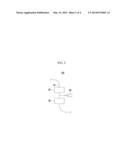
[0038] FIG. 3 is a cross-sectional view schematically illustrating the composite catalyst unit applied to the exhaust gas purification system for a vehicle according to various embodiments of the present invention. Referring to FIGS. 2 and 3, the composite catalyst unit 50 serves to trap particulate matters included in the exhaust gas, and purify the particulate matters through a chemical conversion process.
[0039] Further, the composite catalyst unit 50 serves to reduce nitrogen oxide in the exhaust gas to nitrogen gas by using a reducing agent such as a urea aqueous solution. In addition, the composite catalyst unit 50 serves to remove slip of the reducing agent, which is not reacted, and oxidize and purify CO, HC, or the like generated by the combustion of soot.
[0040] Specifically, the composite catalyst unit 50 is installed at the exhaust pipe 10 at a rear end of the DOC catalyst unit 20. The composite catalyst unit 50 is based on a DPF 61, and an SCR catalyst 71 and an oxidation catalyst 81 are formed on the DPF 61. In various embodiments of the present invention, because the SCR catalyst 71 is formed on the DPF 61, the composite catalyst unit 50 may be defined as an SDPF (SCR on DPF).
[0041] Here, the DPF 61 is provided to trap particulate matters included in the exhaust gas and purify the particulate matters through a chemical conversion process, and may be a diesel particulate filter which is known in the art. The DPF 61 forms or includes a cell passage 63 having a zigzag form, and has porosity equal to or greater than approximately 55% in which a size of a pore is large.
[0042] The SCR catalyst 71 may be coated on an exhaust gas inlet side of the DPF 61, and the oxidation catalyst 81 may be coated on an exhaust gas outlet side of the DPF 61. That is, the SCR catalyst 71 may be coated on a partial region from an end of the inlet side of the cell passage 63 of the DPF 61, and the oxidation catalyst 81 may be coated on a partial region from an end of the outlet side of the cell passage 63.
[0043] In this case, the SCR catalyst 71 may be made of any material selected from Cu or Fe based zeolite and vanadium based materials, or comprise a material selected from Cu or Fe based zeolite and vanadium based materials. The oxidation catalyst 81 may be made of any one noble metal catalyst selected from a group including Pt, Pd, and Rh, or comprise a noble metal catalyst selected from a group consisting of Pt, Pd, and Rh.
[0044] The SCR catalyst 71 may reduce nitrogen oxide in the exhaust gas to nitrogen gas by using a reducing agent such as a urea aqueous solution. Further, the oxidation catalyst 81 may remove slip of the reducing agent, which is not reacted at the SCR catalyst 71, and oxidize and purify CO, HC, or the like generated by combustion of soot when the DPF 61 is regenerated.
[0045] In various embodiments of the present invention, in the DPF 61, a catalyst non-coating region 65 may be present between the inlet side and the outlet side of the cell passage 63. The catalyst non-coating region 65 is provided between a coating region of the SCR catalyst 71 and a coating region of the oxidation catalyst 81.
[0046] The reason why the catalyst non-coating region 65 is formed at the DPF 61 is to prevent the SCR catalyst 71 and the oxidation catalyst 81 from being overlapped through a wall of the cell passage 63 due to high porosity and a large sized pore of the DPF 61. That is, if the SCR catalyst 71 and the oxidation catalyst 81 are overlapped through the wall of the cell passage 63, as described above, the reducing agent for purifying nitrogen oxide is oxidized by the oxidation catalyst 81 including a noble metal, and thus purification efficiency of nitrogen oxide may deteriorate.
[0047] In addition, as the SCR catalyst 71 formed of Cu, Fe, or the like poisons a noble metal and a wash coat in the oxidation catalyst 81, an oxidation function may deteriorate. Therefore, in various embodiments of the present invention, because the catalyst non-coating region 65 is formed at the DPF 61, the reducing agent for purifying nitrogen oxide does not cause an oxidation action by a noble metal catalyst of the oxidation catalyst 81, and may generate a reaction of only the SCR catalyst 71. Therefore, Cu, Fe, or the like may prevent the oxidation catalyst 81 from being poisoned.
[0048] Meanwhile, the exhaust gas purification system 100 of a vehicle according to various embodiments of the present invention further includes an injector 90 (also commonly called "dosing unit" in this field), which injects the reducing agent into the exhaust pipe 10 at a rear end of the composite catalyst unit 50. The injector 90 may be installed at the exhaust pipe 10 between the DOC catalyst unit 20 and the composite catalyst unit 50.
[0049] When the reducing agent is injected into the exhaust pipe 10 through the injector 90, the reducing agent is converted into ammonia (NH3) by heat of the exhaust gas, and nitrogen oxide may be reduced to nitrogen gas (N2) and water (H2O) by a catalyst reaction between nitrogen oxide in the exhaust gas and ammonia by the SCR catalyst 71 of the composite catalyst unit 50. Because the injector 90 is provided as a dosing unit which is known in the art, a detailed description of a structure thereof will be omitted in the present specification.
[0050] Therefore, in the exhaust gas purification system 100 of a vehicle according to various embodiments of the present invention, because the composite catalyst unit 50 is provided in which the SCR catalyst 71 is formed at the inlet side of the cell passage 63 of the DPF 61, and the oxidation catalyst 81 is formed at the outlet side of the cell passage 63, an SCR having a large volume in the related art may be removed.
[0051] In addition, in various embodiments of the present invention, because the oxidation catalyst 81 is formed at the outlet side of the cell passage 63 in the DPF 61 of the composite catalyst unit 50, an amount of slip of the reducing agent, which is discharged without being reacted at the SCR catalyst 71, may be reduced, and CO, HC, or the like, which is generated by combustion of soot when the DPF 61 is regenerated, may be purified while being oxidized.
[0052] That is, in various embodiments of the present invention, because slip of the reducing agent, which is not reacted at the SCR catalyst 71, may be removed by the oxidation catalyst 81 of the composite catalyst unit 50, a reducing agent slip catalyst of the related art may be removed.
[0053] Accordingly, in various embodiments of the present invention, costs for manufacturing an SCR and a reducing agent slip catalyst may be reduced as an SCR and a reducing agent slip catalyst of the related art may be removed, and fuel efficiency may be improved as a weight of a vehicle is reduced.
[0054] In addition, in various embodiments of the present invention, as the SCR catalyst 71 is installed to be closer to an engine in comparison with a case in which an SCR catalyst is installed at a rear end of the DPF 61, that is, the under floor of a vehicle, an exhaust gas temperature is formed to be higher than that of the related art, and as a result, purification efficiency of NOx may be improved.
[0055] Moreover, in various embodiments of the present invention, because the catalyst non-coating region 65 is formed in order to prevent the SCR catalyst 71 and the oxidation catalyst 81 from being overlapped at the DPF 61 of the composite catalyst unit 50, the SCR catalyst 71 may perform its original function without degrading nitrogen oxide purification efficiency, and purification performance of nitrogen oxide may be improved to a level equal to or higher than the same level.
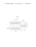
[0056] Meanwhile, as illustrated in FIG. 4, comparing to the present invention in which the oxidation catalyst 81 is formed at the outlet side of the DPF 61 of the composite catalyst unit 50 with a case in which only the SCR catalyst 71 is coated on the DPF 61, CO is rapidly generated at the rear end of the DPF 61 when the DPF 61 is regenerated in a case in which only the SCR catalyst 71 is coated on the DPF 61 (indicated by "A" in the drawing). However, in a case in which the oxidation catalyst 81 is formed at the outlet side of the DPF 61 as in various embodiments of the present invention, CO is not nearly generated at the rear end of the DPF 61 (indicated by "B" in the drawing).
[0057] For convenience in explanation and accurate definition in the appended claims, the terms "front" or "rear", and etc. are used to describe features of the exemplary embodiments with reference to the positions of such features as displayed in the figures.
[0058] The foregoing descriptions of specific exemplary embodiments of the present invention have been presented for purposes of illustration and description. They are not intended to be exhaustive or to limit the invention to the precise forms disclosed, and obviously many modifications and variations are possible in light of the above teachings. The exemplary embodiments were chosen and described in order to explain certain principles of the invention and their practical application, to thereby enable others skilled in the art to make and utilize various exemplary embodiments of the present invention, as well as various alternatives and modifications thereof. It is intended that the scope of the invention be defined by the Claims appended hereto and their equivalents.
User Contributions:
Comment about this patent or add new information about this topic:
Images included with this patent application:
 |  |
 |  |
 |
| Similar patent applications: | |
| Date | Title |
|---|---|
| 2014-10-16 | Exhaust gas purification system for engine |
| 2014-09-25 | Exhaust purification system of internal combustion engine |
| 2014-11-06 | Exhaust gas purification system |
| 2014-11-06 | Methods of maintaining and using a high concentration of dissolved copper on the surface of a useful article |
| 2014-10-02 | Injector mixer for a compact gasification reactor system |
| New patent applications in this class: | |
| Date | Title |
|---|---|
| 2017-08-17 | High-end processing device for purification of exhaust of diesel engine |
| 2016-12-29 | Urea granulation process with scrubbing system |
| 2016-06-02 | Carbon dioxide capture system |
| 2016-03-17 | Combination corona discharge reactor |
| 2016-03-10 | Carbon dioxide capture system |
| New patent applications from these inventors: | |
| Date | Title |
|---|---|
| 2016-05-12 | Method for coating catalyst on diesel particulate filter |
| 2016-05-12 | Method for coating catalyst on diesel particulate filter |
| Top Inventors for class "Chemical apparatus and process disinfecting, deodorizing, preserving, or sterilizing" | |
| Rank | Inventor's name |
|---|---|
| 1 | Abbas Hassan |
| 2 | Rayford G. Anthony |
| 3 | Aziz Hassan |
| 4 | Ebrahim Bagherzadeh |
| 5 | Gregory Borsinger |