Patent application title: CMOS Compatible Microchannel Heat Sink for Electronic Cooling and Its Fabrication
Inventors:
Haluk Külah (Ankara, TR)
Aziz Koyuncuoglu (Ankara, TR)
Tuba Ozyurt Okutucu (Ankara, TR)
IPC8 Class: AF28F2100FI
USPC Class:
165185
Class name: Heat exchange heat transmitter
Publication date: 2013-05-02
Patent application number: 20130105135
Abstract:
The present invention is a CMOS compatible polymer microchannel heat sink
for electronic cooling applications. The heat sink can be fabricated
directly on the chip surface with an insulation layer by standard polymer
surface micromachining techniques. The heat sink device comprises a thin
insulation layer on the chip surface, a thin-film metal layer as bottom
surface, metal side walls, and a polymer top wall over the microchannels
and inlet-outlet reservoirs.Claims:
1-5. (canceled)
6. A method of fabricating microchannel heat sink for electronic cooling applications with liquid, nanofluid and gas, the method comprising the steps of: electroplating a plurality of microchannel side walls on a thin-film metal seed layer between a sacrificial photoresist layer; removing the sacrificial photoresist layer by acetone-IPA-methanol release; wherein the sacrificial photoresist layer and the plurality of microchannel side walls are covered with a polymer top wall before the sacrificial photoresist layer is removed by acetone-IPA-methanol release.
7. The method of claim 6 further comprising: coating a plurality of thin polymer layers on the inner surface of the plurality of microchannels, including the metal surface on the polymer top wall after the sacrificial photoresist layer is removed by acetone-IPA-methanol release.
8. A micro-channel heat sink comprising: a plurality of metal side walls; a thin-film metal seed layer; a plurality of sacrificial photoresist layers; and a polymer top wall; wherein the plurality of photoresist layers and the plurality of metal side walls are covered by the polymer top wall.
9. The micro-channel heat sink of claim 8 wherein the inner surface of the micro-channels including the metal surface on the micro-channel side walls metal seed layer and polymer top wall are coated with thin polymer layers.
10. The micro-channel heat sink of claim 8 wherein cooling is supplied by circulation of a fluid through micro-channels.
11. The micro-channel heat sink of claim 8 wherein a cooling material is selected from a group consisting of liquid, nanofluid and gas.
Description:
TECHNICAL FIELD OF INVENTION
[0001] The present invention is a microchannel heat sink for electronic cooling applications. The heat sink is fabricated using CMOS compatible materials and surface micromachining techniques.
BACKGROUND OF INNOVATION
[0002] With the advances in microelectronics technology, it is now possible to fit high performance, high speed analog and digital circuits of varying purpose into very small volumes. In contemporary integrated circuits (IC), millions of transistors can be fitted into an area of 1 mm2, hence, faster and more functional chips may be produced. On the other hand high density integrated circuits require more power. Therefore, considerable amount of heat is generated in compact volumes and its removal from the system becomes a major design problem. The increase in local temperatures may cause decreased performance or significant damages to the circuits unless the generated heat is removed timely.
[0003] Current commercial cooling methods for electronic applications are basic natural and forced air cooling, liquid cooling systems and some refrigeration based systems. The most widely used method is forced convection air cooling, but heat transfer capacity of air cooling is limited about heat flux values of 60 W/cm2 and modern CPUs are rapidly approaching this limit [1]. Moreover, hot spots on the CPU die cause even higher heat fluxes, about 3 to 8 times more of the average heat flux of the die, at local points on the chip surface [2]. Liquid cooling systems and refrigeration solutions can cope with heat fluxes up to 100 W/cm2, but those systems are bulkier and more complex compared with air cooling systems, increasing the overall cost and causing reliability problems [3]. The use of nanofluids, suspensions of nanoparticles in base fluids, as the working fluid yields an enhancement in heat transfer of more than 50% [4] compared to the use of the base fluid only.
[0004] In order to remove higher heat fluxes from the electronic chip surfaces, several new techniques have been introduced. Among them microchannel heat sinks have attracted significant attention for the last three decades [5]. Microchannel heat sinks are basically very compact heat exchangers with enormous area to volume ratios. This ratio provides a very large heat transfer area over the chip surface therefore the heat removal rates of those heat exchangers are much higher than their macro scale versions. Moreover, the small hydraulic diameters of microchannels provide higher heat transfer coefficients, increasing the heat removal rate even further. There are various fabrication methods for manufacturing microchannel heat sinks such as, micromilling [6], silicon etching [7], or metal electroplating [8].
[0005] Micromilling process requires thick metal substrates and the heat sink is manufactured separately from the microchip. Both factors increase the overall thermal resistance of the cooling system. In monolithic designs the heat sink is manufactured along with the circuit by using microfabrication techniques such as silicon etching and electroplating. This provides lower thermal resistance since the junction-to-fluid distance is much shorter compared to that in separate heat sinks. However silicon etching processes have some drawbacks such as the difficulty of back side etching of finished CMOS wafers which may cause reduced fabrication yield [9], or the need for a design change of the circuit to create area for coolant inlet and outlets [7]. On the other hand, electroplated channels can be fabricated directly on top of the circuits without a need for a design change of the underneath circuitry.
[0006] Joo et al. investigated electroplated metal microchannels for electronic cooling applications [8]. Their electroplated, radially diverging microchannel heat sinks were able to extract 35 W/cm2 with air as the coolant. In this heat sink the top of the channels were covered with the electroplated overhangs extended from the sidewalls, therefore the largest channel width was limited to fewer than 50 microns. On the other hand, the channel height was defined by sacrificial layer thickness which is 70 microns at most. Microchannels with such small dimensions and hydraulic diameters cause enormous pressure drop when used with liquid coolants, therefore the working fluid should be a gas such as air. Since heat transfer coefficient in air cooling is quite low compared to liquid cooling, the maximum heat removal capacity of those microchannel heat sinks were expected to be limited less than 50 W/cm2.
[0007] In order to produce a CMOS compatible surface micromachined microchannel heat sink, the present invention makes use of a polymer top wall instead of electroplated overhangs for covering the microchannels. This design enables fabrication of microchannels that are several hundred microns wide. Therefore higher hydraulic diameter microchannels can be fabricated as well as smeller ones. Besides polymer coating is a simple and CMOS compatible low temperature process. Based on the available pumping power and cooling requirements of the electronic chips, the proposed metal-polymer microchannel heat sinks can be used with various coolants, including gaseous fluids like air, refrigerant, liquid coolants like water, ethylene glycol, or liquid-solid suspensions like nanofluids. With this flexibility, it is possible to obtain much higher heat removal rates from the chip surface.
The Aims of the Invention
[0008] With the proposed invention of CMOS compatible surface micromachined metal-polymer microchannel heat sink, it is aimed to obtain a high heat transfer capacity, light weight, monolithic heat sink structure which can be fabricated easily with standard CMOS compatible surface micromachining techniques and can be operated with gaseous or liquid coolants, or nanofluids.
[0009] Compared with the current commercial cooling technologies, the advantages of the proposed device can be summarized as;
[0010] High area to volume ratio of microchannels increases the overall heat transfer capacity of the heat sink.
[0011] The microchannels can be fabricated on the same wafer as the chip itself.
[0012] Fabrication on the same wafer decreases the distance between heated chip surface and coolant medium, decreasing the thermal resistances in the cooling system significantly.
[0013] Using high performance microchannels in the heat sink enables very compact cooling solutions which can be utilized in mobile computer systems as well.
[0014] Such advantages are common to most of the microchannel heat sink devices studied in the literature before. In addition to these, the proposed invention adds further advantages to similar microchannel heat sink designs, such as;
[0015] The microchannels can be fabricated directly on top of the heated chip surface by using CMOS compatible surface micromachining techniques, instead of silicon etching processes.
[0016] Since the heat sink can be fabricated directly on the chip surface a monolithic cooling system is obtained.
[0017] No design change required on the chip since the microchannels are fabricated over the chip surface with post-CMOS surface micromachining techniques.
[0018] Microchannels with different cross sections and hydraulic diameters can be fabricated, thus enabling usage of liquids and nanofluids as well as gases as coolants, with acceptable pumping power requirements.
DESCRIPTIONS OF FIGURES
[0019] Several figures of the different parts of the polymer microchannel heat sink assembly are given in the appendix to provide easy understanding. Brief descriptions of the figures are as follows;
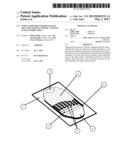
[0020] FIG. 1 Perspective view of microchannels on top of electronic chip with microchannel walls exposed.
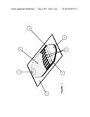
[0021] FIG. 2 Top view of microchannel heat sink with polymer top wall removed.
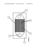
[0022] FIG. 3 Cross sectional view of the microchannels along flow direction.
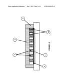
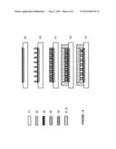
[0023] FIG. 4 Fabrication flow of microchannel heat sink.
DESCRIPTION OF THE PARTS
[0024] Composing parts of the polymer microchannel heat sink are shown in the figures by numbers and the respective names are provided below.
[0025] 1--Silicon wafer under the microelectronic circuit.
[0026] 2--Microelectronic circuit with electrical insulation layer.
[0027] 3--Microchannel side walls.
[0028] 4--Inlet reservoir.
[0029] 5--Outer walls of microchannel heat sink.
[0030] 6--Polymer top wall.
[0031] 7--Outlet reservoir.
[0032] 8--Metal seed layer.
[0033] 9--Photoresist Layer
[0034] 10--Thin Polymer Layers
DETAILED DESCRIPTION OF THE INVENTION
[0035] The present invention is composed of mainly four elements namely;
[0036] Metal seed layer (8) on top of the microelectronic circuit with electrical insulation layer (2),
[0037] Parallel microchannels with metal side walls (3),
[0038] Polymer top wall (6),
[0039] Inlet (4)-outlet (7) reservoirs.
[0040] The electrical insulation layer is deposited on the microelectronic circuit with electrical insulation layer (2) by means of standard vapor deposition techniques, in order to prevent any electrical interaction between the electronic chip and the coolant. The insulation layer can be made of either silicon dioxide, silicon nitride or a polymer film. Microchannels lay on top of the metal seed layer (8) which is deposited over the insulation layer. Microchannels are formed by metal seed layer (8) at the bottom wall and electroplated metal (e.g. Copper, Nickel or Gold) on the microchannel side walls (3) and polymer top wall (6). Thin polymer layers can be coated on inner surface of the microchannels, including the metal surface on the microchannel side walls (3), metal seed layer (8) and polymer top wall (6) as the final step in the fabrication process to prevent corrosion due to contact of coolant and metal.
[0041] Fabrication method of the microchannel heat sink is shown in FIG. 4 schematically. Fabrication is a two-mask process. Microchannel heat sink is fabricated directly on top of the microelectronic circuit with electrical insulation layer (2). First a thin metal seed layer is coated on top of the insulation layer for electroplating process (FIG. 4-a). Seed layer is patterned by using Mask-1 with UV-lithography and wet metal etching, in order to prevent electroplating on top of contact pads of the underneath circuitry. By using Mask-2a sacrificial thick photoresist layer is patterned, forming the microchannels and inlet-outlet reservoirs (FIG. 4-b). Microchannel dimensions are defined by Mask-2 layout and photoresist thickness. Then metal is electroplated between the sacrificial photoresist lines (FIG. 4-c). A thick polymer layer is then coated forming the polymer top wall (6) (FIG. 4-d). This layer provides both visibility and easy sealing. Next, the inlet and outlet connection ports and contact pads are opened in O2 plasma with a thick photoresist layer patterned by again Mask-1, protecting the polymer top wall over microchannels. Finally, the sacrificial photoresist is removed by acetone-IPA-methanol release (FIG. 4-e).
[0042] By using different photoresists, various microchannel thicknesses can be obtained. Moreover, employing the polymer top wall (6), not only narrow microchannels, but also larger channels, as wide as several hundred microns can be fabricated. As a result of dimension flexibility, different working fluids (gas, liquid, nanofluid) can be used as coolants with acceptable pressure drops.
[0043] The overall electronic cooling system is composed of the metal-polymer microchannel heat sink (FIG. 1), inlet and outlet microfluidic interconnection ports (not shown), piping (not shown), pump/compressor (not shown) and external heat exchanger (not shown). Parts other than the microchannel heat sink are standard cooling system components which are already commercially available.
Operation of the System
[0044] The metal-polymer microchannel heat sink provides cooling by means of steady state flow of a working fluid inside the microchannels. The working fluid can be either water or some other coolant, based on the operation conditions and cooling requirements of the chip. The working fluid is pumped in the closed loop cooling system by a pump. Then the fluid flows through the pipes and reaches the inlet reservoir (4) of the polymer microchannel heat sink. In the inlet reservoir the working fluid is distributed to microchannels and flows through microchannels. During the flow the working fluid is heated by the heat flux coming from the microelectronic circuit with electrical insulation layer (2) under the metal seed layer (8). The temperature of the working fluid increases while flowing down the microchannels. The hot working fluid is collected in the outlet reservoir (7) of the heat sink and leaves the microchannel heat sink through the microfluidic interconnection ports.
[0045] The hot working fluid then flows through pipes and radiator (not shown) where it is cooled by ambient air by means of natural or forced convection. The cooled down working fluid flows thorough pipes and reaches pump (not shown) completing the one cooling cycle.
REFERENCES
[0046] [1] Wei, Jie (2008) Challenges in Cooling Design of CPU Packages for High-Performance Servers, Heat Transfer Engineering, 29: 2, 178-187
[0047] [2] Mahajan R., (2006), Cooling a Microprocessor Chip, Proceedings of the IEEE, 94: 8.
[0048] [3] Kandlikar S. G., Grande W., (2004), Evaluation of Single Phase Flow in Microchannels for High Heat Flux Chip Cooling--Thermohydraulic Performance Enhancement and Fabrication Technology, Heat Transfer Engineering, 25: 8, 5-16
[0049] [4] L. Godson, B. Raja, D. Mohan Lal, and S. Wongwises, "Enhancement of heat transfer using nanofluid--An overview", Renewable and Sustainable Energy Reviews 14 (2010) 629-641.
[0050] [5] D. B. Tuckerman, R. F. W. Pease. "Method and means for improved heat removal in compact semiconductor integrated circuits and similar devices utilizing coolant chambers and microscopic channels" U.S. Pat. No. 4,450,472, May 22, 1984
[0051] [6] P. S. Lee, S. V. Garimella, and D. Liu, Investigation of heat transfer in rectangular microchannels, International Journal of Heat and Mass Transfer, vol. 48, 2005, pp. 1688-1704.
[0052] [7] G. Kaltsas, D. N. Pagonis, and A. G. Nassiopoulou, Planar CMOS compatible process for the fabrication of buried microchannels in silicon, using porous-silicon technology, Journal of Microelectromechanical Systems, vol. 12, 2003, pp. 863-872
[0053] [8] Y. Joo, H. C. Yeh, K. Dieu, and C. J. Kim, Air cooling of a microelectronic chip, Journal of Micromechanics and Microengineering, vol. 18, 2008, p. 115022
[0054] [9] R. J. Bezama, E. G. Colgan, J. H. Magerlein, R. R. Schmidt. "Apparatus and methods for microchannel cooling of semiconductor integrated circuit packages" U.S. Pat. No. 7,139,172, Nov. 21, 2006
User Contributions:
Comment about this patent or add new information about this topic:
| People who visited this patent also read: | |
| Patent application number | Title |
|---|---|
| 20140261114 | SYSTEM AND METHOD FOR LOW LOAD OPERATION OF COAL MILL |
| 20140261113 | Process Using Non-fired Refractory Products As A Lining of Large-Volume Industrial Furnaces And Industrial Furnaces Lined With The Non-fired Refractory Products |
| 20140261112 | BIOMASS HIGH EFFICIENCY HYDROTHERMAL REFORMER |
| 20140261111 | Combustion Efficiency Control System with a Stoichiometric Controller for a Laminar Burner System |
| 20140261110 | SECURE ENCLOSURE |
Images included with this patent application:
 |  |
 |  |
 |
| Similar patent applications: | |
| Date | Title |
|---|---|
| 2008-10-23 | Biocompatible material |
| 2008-10-30 | Bank shot guide for billiards |
| 2008-10-30 | Methods of altering poppy characteristics |
| 2008-10-30 | Modified polymer with partitioning agent |
| 2008-10-23 | Sensor electronic |
| Top Inventors for class "Heat exchange" | |
| Rank | Inventor's name |
|---|---|
| 1 | Levi A. Campbell |
| 2 | Chun-Chi Chen |
| 3 | Tai-Her Yang |
| 4 | Robert E. Simons |
| 5 | Richard C. Chu |