Patent application title: LAYERED CORE HEAT EXCHANGER
Inventors:
Modine Manufacturing Company (Racine, WI, US)
Fern L. Tuchowski (South Milwaukee, WI, US)
Adam S. Kimmel (Union Grove, WI, US)
Assignees:
MODINE MANUFACTURING COMPANY
IPC8 Class: AF28D900FI
USPC Class:
165165
Class name: Heat exchange flow passages for two confined fluids interdigitated plural first and plural second fluid passages
Publication date: 2013-04-04
Patent application number: 20130081794
Abstract:
A layered core heat exchanger is provided, and includes first and second
fluid flow passages defined by heat exchanger plates stacked one above
the other. Fluids passing through the first and second fluid flow
passages are in thermal communication with each other through the plates,
in order to provide for the exchange of heat between the fluids. A third
fluid flow passage is provided adjacent one of the flow paths, and has a
lower fluid capacity than the first and second flow passages.Claims:
1. A layered core heat exchanger comprising: a first fluid flow passage
comprising two or more parallel arranged flow paths; a second fluid flow
passage fluidly separate from the first fluid flow passage and in thermal
communication therewith; and a third fluid flow passage arranged adjacent
to a single one of said flow paths.
2. The layered core heat exchanger of claim 1, wherein the first fluid flow passage has a first fluid capacity defined by the internal volume of the first fluid flow passage, the second fluid flow passage has a second fluid capacity defined by the internal volume of the second fluid flow passage, the third fluid flow passage has a third fluid capacity defined by the internal volume of the third fluid flow passage, and the third fluid capacity is substantially smaller than both the first and the second fluid capacities.
3. The layered core heat exchanger of claim 1, wherein the second flow passage comprises two or more parallel arranged flow paths interleaved with the parallel arranged flow paths of the first fluid flow passage.
4. The layered core heat exchanger of claim 1, further comprising a plurality of plates stacked with respect to one another, the first and second fluid flow passages being arranged between the plurality of plates.
5. The layered core heat exchanger of claim 4, wherein the third fluid flow passage is provided in an embossment of one of the plurality of plates.
6. A method of manufacturing a heat exchanger, comprising: forming a plurality of heat exchanger plates; embossing one of the plurality of heat exchanger plates to form a space; forming an inlet and an outlet in fluid communication with the space; and stacking the plurality of plates to form a heat exchanger.
7. The method of claim 6, further comprising joining the plates to one another through brazing.
8. The method of claim 6, further comprising encasing a fin into the space.
Description:
CROSS REFERENCE TO RELATED APPLICATIONS
[0001] This application claims priority to U.S. Provisional Application No. 61/541,570, filed Sep. 30, 2011, the entire contents of which are hereby incorporated by reference herein.
FIELD OF INVENTION
[0002] The present invention relates to a layered core heat exchanger for exchanging heat between fluids.
[0003] A layered core heat exchanger is typically formed from a plurality of heat exchanger plates stacked one above the other. Two fluidly separate flow passages are formed between the plates. Each flow passage includes an inlet and an outlet to the heat exchanger for the respective fluid. The heat exchanger functions to exchange heat between the two fluids such that a first of the fluids is heated and a second of the fluids is cooled.
SUMMARY
[0004] In some embodiments, the invention provides a layered core heat exchanger having a first fluid flow passage for receiving a first fluid and a second fluid flow passage for receiving a second fluid. The second fluid flow passage is fluidly separate from the first fluid flow passage and in thermal communication with the first fluid flow passage to exchange heat between the first and second fluids. The first fluid flow passage comprises two or more flow paths arranged to be fluidly in parallel with one another. Similarly, the second fluid flow passage comprises two or more flow paths arranged to be fluidly in parallel with one another. The heat exchanger also includes a third flow passage adjacent a single one of the flow paths of the first fluid flow passage. The third flow passage has a lower fluid capacity than the first and second flow passages such that heat is transferred to or from the third flow passage with minimal effect on the total heat transfer between the first and second flow passages.
[0005] In some embodiments, the invention provides a layered core heat exchanger formed of a plurality of plates stacked with respect to one another. A first flow passage and a second flow passage are formed between the plurality of plates. The heat exchanger includes a first inlet and a first outlet for the first flow passage and a second inlet and a second outlet for the second flow passage. One of the plurality of plates includes an embossment providing a space between the one of the plurality of plates and another of the plurality of plates. A third inlet and a third outlet are formed in fluid communication with the space to provide a third flow passage in thermal communication with one of the first and second flow passages.
[0006] In yet another aspect, the invention provides a method of manufacturing a heat exchanger including forming a plurality of heat exchanger plates, embossing one of the plurality of heat exchanger plates to form a space, forming an inlet and an outlet in fluid communication with the space, and stacking the plurality of heat exchanger plates to form a heat exchanger.
[0007] Other aspects of the invention will become apparent by consideration of the detailed description and accompanying drawings.
BRIEF DESCRIPTION OF THE DRAWINGS
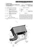
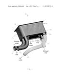
[0008] FIG. 1 is a perspective view of a layered core heat exchanger according to the invention.
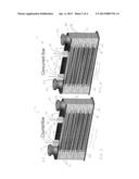
[0009] FIG. 2 is a cross section of the layered core heat exchanger of FIG. 1 illustrating a counterflow arrangement.
[0010] FIG. 3 is a cross section of the layered core heat exchanger of FIG. 1 illustrating a concurrent flow arrangement.
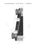
[0011] FIG. 4 is an enlarged view of a portion of the cross section of FIG. 2.
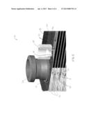
[0012] FIG. 5 is another enlarged view of a portion of the cross section of FIG. 4.
DETAILED DESCRIPTION
[0013] Before any embodiments of the invention are explained in detail, it is to be understood that the invention is not limited in its application to the details of construction and the arrangement of components set forth in the following description or illustrated in the following drawings. The invention is capable of other embodiments and of being practiced or of being carried out in various ways.
[0014] FIG. 1 illustrates a layered core heat exchanger 10 having a mounting plate 12, an end plate 14 and a plurality of heat exchanger plates 16 forming a primary heat exchanger core 17. The heat exchanger plates 16 are stacked with respect to one another in between the mounting plate 12 and the end plate 14. The edges of the heat exchanger plates 16 overlap adjacent edges of the heat exchanger plates 16 and are connected in the overlapping region, for example by brazing in a fluid-tight manner. Formed in each case between two of the adjacent heat exchanger plates 16 are flow paths including a first flow passage 18 for receiving a first fluid and a second flow passage 20 for receiving a second fluid. In some embodiments, the first and second fluids are different fluids, and in other embodiments, the first and second fluids are the same fluid (e.g., a recuperative preheater).
[0015] FIGS. 2-5 illustrate a cross section of the heat exchanger 10 including the first and second flow passages 18, 20. In the illustrated embodiment, the first and second flow passages 18, 20 are arranged in a counterflow manner and in an alternating fashion. The first and second flow passages 18, 20 are fluidly separate and in thermal communication with each other for exchanging heat between the first fluid and the second fluid. The first and second fluids are primary fluids and the heat exchange therebetween is referred to herein as primary heat exchange. In other embodiments, other arrangements of the first and second flow passages for exchanging heat between the first and second fluids may be employed, such as but not limited to concurrent flow and non-alternating flow passages.
[0016] The heat exchanger 10 includes a first inlet 22 and a first outlet 24 in fluid communication with the first flow passage 18 and a second inlet 26 and a second outlet 28 in fluid communication with the second flow passage 20. In the illustrated embodiment, the first and second inlets 22, 26 and first and second outlets 24, 28 are openings or ports mounted to the end plate 14 for facilitating connection to fluid conduits carrying the first and second fluids to and from the heat exchanger 10. In other embodiments, the inlets 22, 26 and outlets 24, 28 may be positioned elsewhere on the heat exchanger 10.
[0017] The end plate 14 includes an embossment 30 projecting away from the heat exchanger plates 16 to form a space 32 between the end plate 14 and an outermost heat exchanger plate 44 of the stacked heat exchanger plates 16. The embossment 30 may encase a secondary heat exchange fin 46 in the space 32. The embossment 30 is formed by embossing the end plate 14, for example using roller dies or patterned rolls. In other embodiments, the embossment 30 may be formed in the mounting plate 12, in either or both sides of the primary heat exchanger core 17, or in multiple such locations.
[0018] A third inlet 34 and a third outlet 36 are formed in the embossment 30 and are in fluid communication with the space 32. First and second ports 38, 40 are coupled to the embossment 30 at the third inlet 34 and the third outlet 36, respectively, for facilitating connection to fluid conduits carrying a third fluid to and from the space 32, thereby forming a third flow passage 42 in the heat exchanger 10. The third fluid is referred to herein as a secondary fluid. In the embodiment where the embossment 30 is formed in multiple locations (described above), multiple secondary fluids may be employed, one for each embossment 30, or a single secondary fluid may be passed through all of the embossments 30 in series.
[0019] The third fluid may be directed through the third flow passage 42 in either direction, i.e., counterflow or concurrent flow with respect to the first fluid in the first flow passage 18. As illustrated in FIG. 2, the third fluid flows in a counterflow direction with respect to the first fluid in the first flow passage 18, i.e., opposite directions. FIG. 3 illustrates the third fluid flowing in a concurrent flow direction with respect to the first fluid in the first flow passage 18, i.e., parallel flow in the same direction.
[0020] The space 32, or third flow passage 42, is adjacent to and in thermal communication with an outermost flow path of the first flow passage 18. Heat exchange between the third flow passage 42 and the top layer, or outermost heat exchanger plate 44, of the primary heat exchanger core 17 is referred to herein as secondary heat exchange. Secondary heat exchange occurs between the primary fluids and the secondary fluid(s).
[0021] In order to promote high effectiveness heat exchange between the primary fluids, it can be advantageous for the heat exchanger core 17 to include a large number of plates 16, so that the surface area available for heat transfer is maximized. The effectiveness can be defined as the temperature change experienced by that one of the primary fluids having the lowest heat capacity, divided by the difference between the entering temperatures of the two primary fluids.
[0022] The amount of heat gained or lost by the primary fluids to the secondary fluid(s) is small compared to the total heat transferred between the primary fluids. This effect is achieved because the flow rates of the primary fluids are substantially higher than the flow rate of the secondary fluid(s), preferably by as much as ten times, and even more preferably by as much as twenty times. In other embodiments, this effect is achieved because the mass flow of the primary fluids is substantially higher than the mass flow of the secondary fluid(s), preferably by as much as ten times, and even more prefererably by as much as twenty times. In other embodiments, this effect is achieved because the heat capacity of the primary fluids is substantially higher than the heat capacity of the secondary fluid(s), preferably by as much as five times, and even more prefererably by as much as ten times. In other embodiments, this effect is achieved because the volume of the primary fluids contained in the primary heat exchanger core 17 is substantially higher than the volume of the secondary fluid(s) in the third flow passage 42, preferably by as much as ten times, and even more prefererably by as much as twenty times.
[0023] In some embodiments, the disparity between the secondary fluid(s) and the first primary fluid can allow for suitably effective heat exchange therebetween even though heat is transferred only between the secondary fluid(s) and that portion of the first primary fluid passing through the outermost flow path of the first flow passage 18. In order to prevent that heat exchange effectiveness from exceeding a desired level (and consequently undesirably overheating or undercooling the secondary fluids), the number of plates 16 used to construct the heat exchanger core 17 can be selected in order to achieve a certain heat capacity ratio between the secondary fluid(s) and that portion of the first primary fluid passing through the outermost flow path of the first flow passage 18.
[0024] In operation, the primary fluids are directed through the primary heat exchanger core 17 at flow rates that are significantly higher than a flow rate of the secondary fluid(s). This enables a useful temperature change in the secondary fluid(s) while causing only a small or insignificant temperature change in the primary fluids. For example, the first fluid may include air, the second fluid may include exhaust, such as a fuel cell exhaust, and the third fluid may include a fuel flow to be supplied to the fuel cell. In some embodiments the fuel flow may be a reformate stream from a high-temperature reformer, and the temperature of the fuel flow may be reduced to a suitable fuel cell operating temperature concurrent with the recuperative preheating of the air (to be supplied to the fuel cell cathode). Thus, the invention eliminates the need for a separate heat exchanger to accomplish a temperature change in the secondary fluid and does not significantly affect the temperatures of the primary fluids, reducing part count and total material weight of the system.
[0025] The invention can be used in other applications as well. By way of example, the invention can function as an exhaust gas recirculation (EGR) cooler, whereby the first fluid includes recirculated exhaust gas from an internal combustion engine and the second fluid includes engine coolant. Fuel for the combustion engine can be advantageously preheated by passing through the heat exchanger as the third fluid, thereby being placed into heat transfer relationship with a portion of the recirculated exhaust gas. The number of plates 16 can be selected so that the heat capacity ratio of the fuel and said portion of the recirculated exhaust gas limits the achievable effectiveness of the heat exchange therebetween.
[0026] The heat exchanger 10 is formed by providing a plurality of heat exchanger plates stacked on top of one another to form fluid passages between adjacent heat exchanger plates, embossing one of the plurality of heat exchanger plates to form a space, forming an inlet and an outlet in fluid communication with the space, and connecting the heat exchanger plates to form the heat exchanger. The heat exchanger 10 is used by passing primary fluids through the primary heat exchanger core 17 at a first set of flow rates to exchange heat with one another, and passing a secondary fluid through the embossment 30 at a second flow rate to exchange heat with the primary fluids. The second flow rate is significantly lower than the first set of flow rates.
[0027] Thus, the invention provides, among other things, a layered core heat exchanger having primary and secondary heat exchange functions, where the secondary heat exchange function is accomplished with an insignificant effect on the primary heat exchange function.
User Contributions:
Comment about this patent or add new information about this topic:
Images included with this patent application:
 |  |
 |  |
 |
| Similar patent applications: | |
| Date | Title |
|---|---|
| 2011-09-01 | Wound layered tube heat exchanger |
| 2010-09-16 | Corrugated micro tube heat exchanger |
| 2013-01-24 | Formed microchannel heat exchanger |
| 2010-04-01 | Rackmount rear door heat exchanger |
| 2010-10-28 | Holder for a heat exchanger |
| New patent applications in this class: | |
| Date | Title |
|---|---|
| 2017-08-17 | Device for heat exchange |
| 2016-07-14 | Heat exchanger including furcating unit cells |
| 2016-03-31 | Header of heat exchanger and heat exchanger provided with the same |
| 2015-05-28 | Oil cooler |
| 2015-05-21 | Fluid heat exchanging apparatus |
| New patent applications from these inventors: | |
| Date | Title |
|---|---|
| 2015-10-01 | Palm kernel methyl ester torch fuel |
| 2015-06-04 | Methyl ester torch fuel |
| 2015-02-19 | Burner cup |
| 2013-03-28 | Heat exchanger and method of manufacturing the same |
| Top Inventors for class "Heat exchange" | |
| Rank | Inventor's name |
|---|---|
| 1 | Levi A. Campbell |
| 2 | Chun-Chi Chen |
| 3 | Tai-Her Yang |
| 4 | Robert E. Simons |
| 5 | Richard C. Chu |