Patent application title: Thermodynamic Device For Refrigeration And Air Conditioning
Inventors:
Edson Rocha (Campinas, BR)
IPC8 Class: AF28D1504FI
USPC Class:
16510426
Class name: Liquid fluent heat exchange material utilizing change of state utilizing capillary attraction
Publication date: 2013-02-14
Patent application number: 20130037243
Abstract:
A thermodynamic capillary device for use in refrigeration and air
conditioning systems has a tube (1) internally containing a plurality of
capillary tubes (2) having facing flanges (3) and (4), each flange
installed on an end of the tube (1), the capillary device installed on a
vapor line (5) of the refrigeration or air conditioning system. The
device has, on its top portion, a feeding tube (6) with a cooling jet
and, on its bottom portion, a return tube (7), the device formed so that
the assembly can be fitted into a housing (8), and integrated to the
refrigeration or air conditioning system composed by a compressor (9), a
mini condenser (10) and an expansion valve (11).Claims:
1. A thermodynamic capillary device for use in a refrigeration or air
conditioning system including a compressor (9), a mini condenser (10) and
an expansion valve (11), the device comprising: a tube (1) internally
comprising a plurality of capillary tubes (2) and having facing flanges
(3) and (4), each flange installed on an end of the tube (1), said
capillary device installed on a vapor line (5) of the refrigeration or
air conditioning system, said device having, on a top portion thereof, a
feeding tube (6) with a cooling jet and, on a bottom portion thereof, a
return tube (7), the assembly located within a housing (8).Description:
BACKGROUND
[0001] The present invention refers in general to a new thermodynamic device for refrigeration and air conditioning systems, and specifically a capillary device used to increase the efficiency of the system. Such a device is a new concept and provides an important technological and functional improvement, according to the latest engineering concepts and to the required regulations and technical specifications. It has particular features that comply with the patentability requirements of novelty and inventive step, resulting in a series of real and extraordinary technical, practical and economic advantages.
[0002] Since the introduction of condensers (heat exchangers) in such systems, nearly 150 years have passed and the concept of the condenser has gone through several changes to improve its performance such as evaporative condensers, forced air condensers and tube condensers with symmetrically or geometrically rearranged tubes.
[0003] Indeed such condensers are still in the market as part of the general refrigeration systems which may use gas, water, etc.
[0004] However, up to the present moment, one could not solve the low efficiency (usually only 45%, maximum 65%) problem of such devices, which happens due to the complexity of the embodiment for use in the existing applications. One of the major drawbacks of these condensers is due to its limited capacity of a maximum of 65% efficiency in condensing and refrigerating and, in various situations, the heat exchange to the outdoor environment cannot be improved.
[0005] In this sense, currently the best equipment has a 47% rejection. Therefore chillers and high demand type refrigeration units are limited in this critical rejection point, making the refrigeration and air conditioning system designers reevaluate such situation.
[0006] One problem that leads to a worsening of the performance of the system, is that when any condenser gets dirty, the refrigeration or air conditioning system starts to require more electrical power and must move more heat to the outer environment, with the heat generated by the compression, which can rise up to the point of being shut off by the safety system. This condition is further worsened when there is no preventive maintenance, causing the drawback of dragging the oil of the crankcase of the compressor, increasing even more the problem by drawing the oil into the condenser and vaporizer, considerably decreasing the enthalpy of the vaporizer, thus making the system work for hours without getting the desired temperature.
[0007] Therefore, the system as a whole gets worse with great consumption of oil, which has to be frequently drained from the air conditioning system to a safe place in order not to contaminate the environment. Besides this, there is also the wear and tear of the compressor that works at a high temperature in the cylinders and headstock, thus decreasing its service life due to the carbonization of the oil, demanding, in some cases, the insertion of a oil cooler. However, once the oil goes several times through the heat process above the fulgency point, a type of material sticks to the walls of the discharge tubes or condensers in the form of sludge, inhibiting even more the heat exchange to the outer environment.
[0008] In some cases, already confirmed by packing plants, 600 liters of oil a month were lost due to lack of a better control and to the heat generated by the compression, turning the oil into overheated vapor along with the refrigerating liquid, taking it into the whole system. It then settles in cold areas of the refrigeration equipment, greatly increasing the cost of operation.
SUMMARY OF THE INVENTION
[0009] In order to overcome these and other drawbacks, the object of the present invention was created, which is a thermodynamic device, developed with inventive step, with the objective of using only 10% of the condenser capacity once the device is inserted in any existing or new system. The field of application of the object of the present invention is thermodynamics and, normally, it is installed on a discharge side of the compressor and the vapor by descending pressure, in such a way that a good part goes through the device, demanding less work of the condenser. The vapor is compressed and by the phenomenon of dragging, it is drained through the capillary device and the vapor is completely transformed into cold liquid and deposited in a thermally sealed reservoir. As an example: in thermodynamics, 1.05 liters of water per second corresponds to 1.05 Kcal and 1.05 liters ° C./s.ton. The necessary water flow would be equal to 1.05 divided by the rise in temperature in ° C. allowed for the water through the condenser, even more in condenser using air with the present invention. The calculation is done by dividing the temperature by the 1.05 flow, which means that the lower the temperature of the vapor and liquid, the greater its global performance, and in the specific case of the present invention we were able to attain the highest mass value possible, resulting in oil savings in the compressor crankcase, 0.1% of drag in the same but with a quality return resource, totally preventing the presence of oil in the vaporizer. The vapor/liquid is dragged at a flow speed of (10×1.05) per second and afterwards, when necessary, it is pumped to the vaporizers whichever utility it might have.
[0010] The process is reversible and adiabatic for it includes the device of the present invention installed before the condenser and which drags the vapor fluid of the discharge of the compressor to its core by the pressure force up to the point of convergence (capillary) where there is an abrupt drop of pressure in the linear portion of the capillary and, in this portion through the external portion of the capillary housed by a pipe where the device is bathed by the refrigerating liquid that comes from the condenser. In this section, there is an abrupt refrigeration and instantaneously the vapor decreases in pressure and becomes liquid at the maximum saturation point and in high flow speed into the muzzle and deposits the liquid according to the drawing herein bellow.
[0011] The work carried out by the compressor keeps the pressures constant between the present capillary device and the small condenser, so that said capillary device produces the amount of liquid already under low pressure. The condenser cools down the capillary device and it produces a 100% liquid, which is already in a working conditions for the vaporizer. In same cases, it can eliminate the expansion valve because the fluid comes already in the right temperature for the vaporizer, depending on the project and its application.
[0012] For the perfect functioning of the capillary device of the present invention, the produced liquid is pumped by the pump as shown in the drawing for the cold system, whichever the system may be.
[0013] Indeed, the capillary device is a great advancement in technology, for it is possible to install it on the discharge of any compressor and unload the condenser by up to 50%.
[0014] Because it increases the exchange area, the capillary device is vested with great novelty, for it instantaneously turns the vapor into liquid without any reliance on high pressure, once it lowers the pressure of any system where it is applied. In some cases there is the need of installing a pressure meter to keep the discharge pressure without damaging the oil and energy consumption, in such a way that this ensemble of inventive factor involve the capillary device in a reduces condenser inside the very thermal cycle machine with compressor, a thermally insulated reservoir and pump to keep a certain pressure of the super cold liquid, for its temperature could be well bellow zero in case of meatpacking facilities (-50° C.), and air conditioners between 0° and 8°.
[0015] While the change in vapor/liquid occurs, the temperature under the above conditions also changes in proportion to the heat produced by the drag. Its kinetic energy is capable of carrying out the work with a minimum of thermal exchange, in such manner that the efficiency is increased in the drag produced by the thermodynamic capillary device of the present invention.
[0016] This phenomenon of high pressure to low pressure of the refrigerating means, whichever it may be in the general refrigerating systems, produces kinetic energy of the vapor to the liquid with a specific volume that is 10 times greater than the conventional, representing an economy from 50% up to 75%, depending on each application.
[0017] The phenomenon is also characterized by the capillary process according to each application, and the vapor compressed by the compressors flows at great speed, producing even more vapor/liquid up to the point of a balanced mass saturation.
[0018] Therefore the present invention comprising the thermodynamic capillary device for refrigeration, allows for the stability of the oil in any compressor, keeping its features and performance, not needing changes or replenishing of the oil, what is a solution to the problems of oil carbonization and the frequent changes of oil in a large system, such as the systems for meatpacking units and warehouses, poultry raisers, refrigerated trucks, automotive air conditioners, screw chillers, centrifugal, self contained, split systems, and refrigeration in general.
BRIEF DESCRIPTION OF THE DRAWINGS
[0019] In order to better describe the object of the present patent and therefore obtain a better understanding of its features, according to its preferred embodiment, a set of drawings is enclosed herewith, which represents, without limitation, the following:
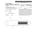
[0020] FIG. 1 represents a cross section view of the thermodynamic capillary device object of the present patent;
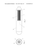
[0021] FIG. 2 represents a longitudinal section of the thermodynamic capillary device object of the present patent;
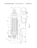
[0022] FIG. 3 represents a schematic view of a thermodynamic system provided with a the capillary device with a pre-cooling jet, which is the object of the present patent;
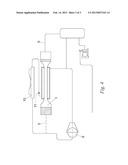
[0023] FIG. 4 represents a schematic view of another thermodynamic system provided with the capillary device object of the present patent, connected between the condenser and the compressor.
DETAILED DESCRIPTION OF THE INVENTION
[0024] According to the above mentioned drawings, and in detail, the thermodynamic capillary device comprises a tube (1) internally comprising a plurality of capillary tubes (2) and facing end flanges (3) and (4), each one installed on an end of the tube (1), being said capillary device installed on the vapor line (5) of the thermodynamic system. Said device can comprise, on its top portion, a feeding tube (6) with a cooling jet and, on its bottom portion, a return tube (7), in such a way that the entire assembly is surrounded by a housing (8) and integrated to a system comprising a compressor (9), mini condenser (10) and expansion valve (11).
[0025] We do not know any thermodynamic capillary device that comprises all the above described constructive and functional features, and also that is directly or indirectly as effective as the device object of the present patent.
[0026] After describing and illustrating the present invention, one has to understand that it could suffer several changes and variations that do not differ from the spirit and scope of the invention, as defined by the claim herein bellow.
User Contributions:
Comment about this patent or add new information about this topic:
| People who visited this patent also read: | |
| Patent application number | Title |
|---|---|
| 20200250067 | Autonomous Vehicle Testing Systems and Methods |
| 20200250066 | SYSTEMS AND METHODS FOR ROBUST ANOMALY DETECTION |
| 20200250065 | CLICK HEATMAP ABNORMALITY DETECTION METHOD AND APPARATUS |
| 20200250064 | INFORMATION PROCESSING APPARATUS AND DISTRIBUTED PROCESSING SYSTEM |
| 20200250063 | AUTOMATED IDENTIFICATION OF EVENTS ASSOCIATED WITH A PERFORMANCE DEGRADATION IN A COMPUTER SYSTEM |
Images included with this patent application:
 |  |
 |  |
| Similar patent applications: | |
| Date | Title |
|---|---|
| 2013-03-21 | Electronic device and heat dissipation module and centrifugal fan thereof |
| 2013-03-21 | Thermally conductive reinforcing sheet, molded article and reinforcing method thereof |
| 2012-05-10 | Finned tube for evaporation and condensation |
| 2012-06-21 | Device for cooling and condensing fuel vapors |
| 2009-01-01 | Viscous heater, refrigerant compressor and control |
| New patent applications in this class: | |
| Date | Title |
|---|---|
| 2019-05-16 | Method for preparing porous wick and product prepared by the same |
| 2019-05-16 | Semiconductor device assembly with vapor chamber |
| 2019-05-16 | Straight-through structure of heat dissipation unit |
| 2018-01-25 | Diphasic cooling loop with satellite evaporators |
| 2017-08-17 | Heat pipe |
| Top Inventors for class "Heat exchange" | |
| Rank | Inventor's name |
|---|---|
| 1 | Levi A. Campbell |
| 2 | Chun-Chi Chen |
| 3 | Tai-Her Yang |
| 4 | Robert E. Simons |
| 5 | Richard C. Chu |