Patent application title: APU SELECTIVE COOL DOWN CYCLE
Inventors:
Brian C. Dede (San Diego, CA, US)
Brian C. Dede (San Diego, CA, US)
Stacey H. Light (San Diego, CA, US)
IPC8 Class: AF01D2512FI
USPC Class:
60772
Class name: Power plants combustion products used as motive fluid process
Publication date: 2013-02-07
Patent application number: 20130031911
Abstract:
An APU has a control for controlling a load on the APU from an associated
aircraft. The control further receives information with regard to a
temperature challenge around the APU. If the temperature challenge
exceeds a predetermined threshold, then the control operates the APU with
a reduced load in a cool down cycle to reduce the heat load from the APU
on an associated tail cone. A method is also disclosed.Claims:
1. An auxiliary power unit (APU) comprising: a compressor for compressing
air and delivering it into a combustion chamber, the air being mixed with
fuel and combusted in the combustion chamber, and passed over a turbine,
said turbine driving a generator to generate electricity; and a control
for controlling a load on the APU from an associated aircraft, said
control further receiving information with regard to a temperature
challenge around the APU, and if the temperature challenge exceeds a
predetermined threshold, then said control operating said APU with the
load reduced in a cool down cycle to reduce the heat load from the APU on
an associated tail cone.
2. The APU as set forth in claim 1, wherein said reduced load includes reducing the amount of electricity tapped from the generator to the associated aircraft.
3. The APU as set forth in claim 2, wherein a valve controls a flow of air from the compressor to the combustion chamber, and also serves to pass some of the air from the compressor to the associated aircraft, said valve being actuated to reduce the flow of air to the aircraft in the cool down cycle.
4. The APU as set forth in claim 1, wherein the temperature challenge is determined by sensing a temperature.
5. The APU as set forth in claim 4, wherein the sensed temperature is an ambient temperature.
6. The APU as set forth in claim 5, wherein the ambient temperature is taken from inside the associated tail cone that receives the APU.
7. The APU as set forth in claim 5, wherein the ambient temperature is taken from outside the associated tail cone that receives the APU.
8. The APU as set forth in claim 4, wherein the sensed temperature includes an exhaust gas temperature downstream of the turbine.
9. A method of selectively cooling an auxiliary power unit (APU) including the steps of: operating the APU, and identifying a shutdown decision; sensing a temperature challenge of a tail cone associated with the APU, comparing the temperature challenge to a threshold; and operating the APU in a cool down cycle prior to shut down if the temperature challenge exceeds the predetermined threshold, and not operating the APU in the cool down cycle if the temperature challenge does not exceed the predetermined threshold.
10. The method as set forth in claim 9, wherein the temperature challenge is evaluated based upon an ambient temperature.
11. The method as set forth in claim 10, wherein the ambient temperature is taken from inside the associated tail cone that receives the APU.
12. The method as set forth in claim 10, wherein the ambient temperature is taken from outside the associated tail cone that receives the APU.
13. The method as set forth in claim 10, wherein the temperature challenge is also evaluated based upon an exhaust gas temperature.
14. The method as set forth in claim 9, wherein the cool down cycle reduces the load on the APU from an associated aircraft.
15. The method as set forth in claim 14, wherein the supply of electricity from a generator associated with the APU to the aircraft is reduced in the cool down cycle.
16. The method as set forth in claim 14, wherein a volume of air diverted from a compressor associated with the APU to the aircraft is reduced in the cool down cycle.
Description:
BACKGROUND
[0001] This application relates to an auxiliary power unit ("APU") which is put through a cool down cycle at shutdown, but only in an extreme temperature situation.
[0002] APUs are known, and are typically provided in an aircraft, and started prior to actuation of the main aircraft gas turbine engines. The APU provides electric power through a generator for use on the aircraft prior to the startup of the main gas turbine engines. In addition, the APU may supply air for use in the aircraft cabin, and to start the aircraft engines.
[0003] Once the main aircraft engines have started, then the APU may be shut down. The APUs typically are under a heavy load just prior to shutdown, in that they are supplying a good deal of electricity, plus air to start the main gas turbine engines. Thus, they can be quite hot at shutdown.
[0004] Aircraft tail cones typically house the APU. The aircraft tail cones have traditionally been made of a metal, however, more recently they have been formed of various fiber composite materials. As an example, carbon fiber materials are being utilized.
[0005] Such fiber materials cannot withstand the high temperatures that the prior metal tail cones could withstand. As an example, an aluminum tail cone can withstand 450° Fahrenheit (232° Celsius) while the composite tail cones may only withstand 200° Fahrenheit (93° Celsius).
SUMMARY
[0006] An APU has a control for controlling a load on the APU from an associated aircraft. The control further receives information with regard to a temperature challenge around the APU. If the temperature challenge exceeds a predetermined threshold, then the control operates the APU with a reduced load in a cool down cycle to reduce the heat load from the APU on an associated tail cone. A method is also disclosed.
[0007] These and other features of the present invention can be best understood from the following specification and drawings, of which the following is a brief description.
BRIEF DESCRIPTION OF THE DRAWINGS
[0008] FIG. 1 schematically shows an aircraft tail cone and APU.
[0009] FIG. 2 is a flow chart.
DETAILED DESCRIPTION OF THE INVENTION
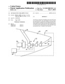
[0010] An APU 22 is shown mounted in a tail cone 20 of an aircraft. As mentioned above, the tail cone 20 may be formed of a composite material, such as a carbon fiber material. The APU 22 includes a compressor 24 drawing air from an air inlet 26. The air is compressed and passed through a combustion chamber 28, and then products of that combustion pass across a turbine 30 before existing through an exit nozzle 32.
[0011] The turbine 30 drives the compressor 24, and further drives a gearbox 34 which in turn drives a generator 36. The generator 36 provides electricity to a control 38 for use on the aircraft.
[0012] In addition, a diverter valve 40 may be positioned downstream of the compressor 24. As shown, a portion of the air 42 compressed by the compressor 24 can be delivered to the aircraft also. As shown, the control 38 may also control the valve 40 in one embodiment.
[0013] A temperature sensor 44 is shown schematically, and also communicates with the control 38. The temperature sensor 44 may sense an ambient temperature. The ambient temperature may be outside or inside tail cone 20. Another sensor 44' may sense the temperature of the gas in the exhaust 32. Rather than these two temperatures, other variables indicative of a high heat load potentially being placed on the tail cone 20 could be sensed. Generally, these variables could be called a temperature challenge.
[0014] In one embodiment ambient temperature is utilized, and in another embodiment ambient temperatures plus the exhaust gas temperature are both utilized and compared to a predetermined threshold. If the threshold is exceeded, then the APU 22 is put through a cool down cycle at shutdown.
[0015] In a cool down cycle, the APU 22 continues to compress air, combust fuel and drive the turbine 30, and hence the compressor 24 before shutdown. However, the load on the APU 22 is reduced. As an example, the diverter valve 40 is actuated such that all of the air is directed into the combustion chamber 28. In addition, the tapping of electricity from the generator 36 may be reduced, or stopped. In addition, if there is a clutch provided between the output shaft and a gear box, that clutch can be opened during a cool down mode.
[0016] Both of these steps can be taken, since the time for the APU 22 to be shut down is typically associated with the main gas turbine engines on the aircraft being operational, and thus able to supply electricity and air on their own.
[0017] The APU 22 is run in the cool down mode for a period of time sufficient to reduce the heat mass of the APU 22, such that the APU 22 can finish cooling down without damage to the tail cone 20.
[0018] A cool down cycle could potentially harm the turbine 30. However, it is not used in every instance of shutting down the APU 22, and thus the damage to the turbine 30 should be minimized.
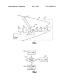
[0019] Instead, as shown in FIG. 2, once a shutdown decision 100 is reached, the temperature challenge is identified. The temperature challenge is compared to the same threshold 102. If the temperature challenge (ambient and/or exhaust gas temperatures or some other variable, for example) is indicative of a potential of heat damage to the tail cone, then the cool down cycle is run 104. If it is not, the APU is simply shut down 106. The cool down cycle can operate for a number of minutes, for example less than ten minutes and on the order of about five minutes. The method depicted in FIG. 2 can be executed by control 38 of FIG. 1. Selectively running the cool down cycle can lower thermal loads on the tail cone 20 and allow for the use of composite materials in the tail cone 20 without adding the weight and expense of thermal insulation blankets which may otherwise be needed to limit tail cone temperature.
[0020] Although embodiments of this invention have been disclosed, a worker of ordinary skill would recognize that certain modifications would come within the scope of this invention. For that reason, the following claims should be studied to determine the true scope and content of this invention.
User Contributions:
Comment about this patent or add new information about this topic:
Images included with this patent application:
 |  |
| Similar patent applications: | |
| Date | Title |
|---|---|
| 2013-09-26 | Bi-metallic actuator for selectively controlling air flow between plena in a gas turbine engine |
| 2013-09-26 | Active control of compressor extraction flows used to cool a turbine exhaust frame |
| 2013-07-11 | Electric supercharged co-power hybrid vehicle |
| 2013-09-26 | Non-combustion energy source and configuration for brayton cycle heat engines |
| 2009-06-25 | Machine having selective ride control |
| New patent applications in this class: | |
| Date | Title |
|---|---|
| 2022-05-05 | Gas turbine plant and exhaust carbon dioxide recovery method therefor |
| 2018-01-25 | Engine, rotary device, power generator, power generation system, and methods of making and using the same |
| 2017-08-17 | Fuel drain system and method |
| 2017-08-17 | Turbine stator vane with multiple outer diameter pressure feeds |
| 2016-12-29 | Method for operating a gas turbine installation and the same |
| New patent applications from these inventors: | |
| Date | Title |
|---|---|
| 2014-11-13 | Inlet duct screen assembly |
| 2013-09-05 | Auxiliary power unit inlet |
| 2013-07-11 | Automatic engine noise reduction |
| 2013-01-17 | Fire resistant structural mount yoke and systemaanm dede; brian c.aaci san diegoaast caaaco usaagp dede; brian c. san diego ca usaanm lau; davidaaci san diegoaast caaaco usaagp lau; david san diego ca usaanm jewess; gordon f.aaci rzeszowaaco plaagp jewess; gordon f. rzeszow pl |
| 2013-01-03 | Auxiliary power unit inlet |
| Top Inventors for class "Power plants" | |
| Rank | Inventor's name |
|---|---|
| 1 | Gabriel L. Suciu |
| 2 | Patrick Benedict Melton |
| 3 | Eugene V. Gonze |
| 4 | Thomas Edward Johnson |
| 5 | Frederick M. Schwarz |