Patent application title: Variable Valve Control Apparatus for Internal Combustion Engine
Inventors:
Yukimori Sasaki (Shizuoka-Ken, JP)
Assignees:
SUZUKI MOTOR CORPORATION
IPC8 Class: AF01L1344FI
USPC Class:
123 9015
Class name: Internal-combustion engines poppet valve operating mechanism with means for varying timing
Publication date: 2012-09-20
Patent application number: 20120234272
Abstract:
A variable valve mechanism control apparatus ensures intake negative
pressure in an idling state, decelerating state, coasting state, and a
decelerating and coasting state, to operate accessories or a brake device
with the ensured intake negative pressure. In the variable valve
mechanism control apparatus of an internal combustion engine including a
variable valve mechanism which changes the phase of an operating angle of
an engine valve, and a control device which changes the phase of the
variable valve mechanism, when the temperature of the internal combustion
engine is greater than a certain value which can be treated as a
post-warm-up state, the accelerator opening is less than a certain value
which can be treated as an idling state, and the intake negative pressure
is less than a predetermined value, the phase is changed to converge to a
predetermined phase at which a predetermined intake negative pressure
occurs.Claims:
1. A variable valve mechanism control apparatus of an internal combustion
engine, comprising: a variable valve mechanism which changes the phase of
an operating angle of an engine valve; and a control device which changes
the phase of the variable valve mechanism, wherein in a case in which the
temperature of the internal combustion engine is greater than a certain
value which can be treated as a post-warm-up state, the accelerator
opening is less than a certain value which can be treated as an idling
state, and the intake negative pressure is less than a predetermined
value, the phase is changed so as to converge to a predetermined phase at
which a predetermined intake negative pressure occurs.
2. A variable valve mechanism control apparatus of an internal combustion engine according to claim 1, wherein the variable valve mechanism is provided for an intake valve, and the predetermined phase at which a predetermined intake negative pressure occurs, is set at an intermediate advance angle position at which the intake negative pressure increases, and the intermediate advance angle position is defined by intake negative pressure reduction associated with intake blowback, which increases as the operating angle phase of the intake valve is delayed, and by intake negative pressure reduction associated with an increase in internal EGR according to valve overlap with an exhaust valve, which increases as the operating angle phase of the intake valve is advanced.
3. A variable valve mechanism control apparatus according to claim 1, wherein the variable valve mechanism is provided for an intake valve, and the predetermined phase at which a predetermined intake negative pressure occurs, is set at the most advanced angle position of the operating angle phase of the exhaust valve, at which the intake negative pressure increases associated with a decrease in internal EGR according to valve overlap with the intake valve, which decreases as the operating angle phase of the exhaust valve is advanced.
Description:
CROSS-REFERENCE TO RELATED APPLICATIONS
[0001] The present application claims priority from JP 2011-059168 filed in the Japanese Patent Office on Mar. 17, 2011, the disclosure of which is hereby incorporated herein by reference.
BACKGROUND OF THE INVENTION
[0002] The present invention relates to a control technique for operating accessories or a brake device, with use of intake negative pressure generated by an internal combustion engine.
[0003] In particular, the present invention relates to control of intake negative pressure for operating accessories or a brake device, in an internal combustion engine having a variable valve mechanism.
[0004] Normally, in a brake device in an automobile, there is combined a brake booster for increasing the braking force.
[0005] This brake booster is generally one that uses negative pressure within an intake manifold.
[0006] On the other hand, in an internal combustion engine with a variable valve mechanism, the control target value of the variable valve mechanism is set so as to lower the intake negative pressure in order to enhance fuel economy.
[0007] Consequently, the negative pressure required for braking may not be reliably provided in some cases.
[0008] Moreover, as operations of accessories, a purge operation for drawing fuel vapors from a fuel tank into a combustion chamber, and an operation for drawing an air-fuel mixture which has leaked from the combustion chamber of the internal combustion engine into the crankcase, or drawing blow-by gas which is combustion gas, are performed with use of intake negative pressure.
[0009] At this time, with an engine provided with a variable valve mechanism having a sufficient phase shift angle, the intake negative pressure can be raised or lowered by changing the phase.
[0010] There is known a technique for controlling a variable valve mechanism in order to ensure the intake negative pressure required for a brake booster.
[0011] For example, there is one disclosed in Japanese Laid-open Patent Application Publication No. 2005-163635, discussed later.
[0012] Recent gasoline engines are set to suppress an increase in intake resistance associated with throttle closure, and lower the intake negative pressure in the idling state, in order to enhance fuel economy.
[0013] In a conventional variable valve mechanism control apparatus of an internal combustion engine, brake booster capacity enables booster mechanism operation even when the intake negative pressure temporarily becomes low. However, if the intake negative pressure remains low for a somewhat prolonged period of time, the booster mechanism operation deteriorates, depending on the frequency of use of the brake, and booster mechanism operation is eventually lost. As a result, only the operating force of the driver operates the brake device, and this is inconvenient.
[0014] Moreover, even when the intake negative pressure temporarily becomes low, it is only the operation of the accessories that stops during this time. However if the intake negative pressure remains low for a somewhat prolonged period of time, fuel vapor and blow-by gas cannot be processed, and consequently there will be an inconvenience in that deterioration of lubricating oil may be accelerated and unburned gas may be discharged into the atmosphere in some cases.
[0015] However, if control is performed so as to set the intake negative pressure low in the idling state, the required intake pipe pressure may not be reliably provided in some cases when the engine load is high, or at a high altitude where atmospheric pressure is low.
[0016] For example, as disclosed in Japanese Laid-open Patent Application Publication No. 2009-085145, in a case in which the phase of a variable valve mechanism is changed by detecting brake booster negative pressure, the negative pressure is lowered by a braking operation. Therefore, increase of the brake booster negative pressure by changing the phase can be achieved. Also, while this control is being performed, operations of accessories can be performed in association with this.
[0017] However, in those cases in which hill-climbing continues to be performed at a high altitude, then in a situation in which there is no use of the brake and negative pressure is ensured for the brake booster, phase change control of the variable valve mechanism for ensuring negative pressure for the brake device is not performed. Therefore, the intake negative pressure continues to stay extremely low, so there is an inconvenience in that the opportunity to process fuel vapor and blow-by gas is significantly reduced.
[0018] It is therefore an object of an aspect of the present invention to ensure intake negative pressure in an idling state, a decelerating state, a coasting state, and a decelerating and coasting state, and to reliably operate accessories or a brake device, with the ensured intake negative pressure.
BRIEF SUMMARY OF THE INVENTION
[0019] In order to eliminate the inconveniences described above, an aspect of the present invention provides a variable valve mechanism control apparatus of an internal combustion engine including a variable valve mechanism which changes the phase of an operating angle of an engine valve, and a control device which changes the phase of the variable valve mechanism, and in a case in which the temperature of the internal combustion engine is greater than a certain value which can be treated as a post-warm-up state, the accelerator opening is less than a certain value which can be treated as an idling state, and the intake negative pressure is less than a predetermined value, the phase is changed so as to converge to a predetermined phase at which a predetermined intake negative pressure occurs.
[0020] As described in detail above, according to an aspect of the present invention, there is provided a variable valve mechanism control apparatus of an internal combustion engine including a variable valve mechanism which changes the phase of an operating angle of an engine valve, and a control device which changes the phase of the variable valve mechanism, and in a case in which the temperature of the internal combustion engine is greater than a certain value which can be treated as a post-warm-up state, the accelerator opening is less than a certain value which can be treated as an idling state, and the intake negative pressure is less than a predetermined value, the phase is changed so as to converge to a predetermined phase at which a predetermined intake negative pressure occurs.
[0021] Consequently, when the intake negative pressure is low in an idling state after the internal combustion engine has undergone a warm-up operation, the intake negative pressure is increased by changing the phase with the variable valve mechanism. Therefore, operations of a brake device and accessories can be ensured. Furthermore, in other cases in which the intake negative pressure is high, there can be provided a phase which meets requirements of fuel economy and requirements of emission gas purification performance, and superior fuel economy and operations of the brake device and accessories can both be ensured at the same time.
BRIEF DESCRIPTION OF THE DRAWINGS
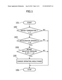
[0022] FIG. 1 is a flow chart showing the control procedure of a variable valve mechanism, in a first embodiment of the present invention;
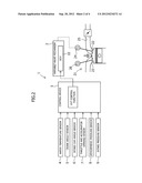
[0023] FIG. 2 is a system diagram of an internal combustion engine, in the first embodiment of the present invention;
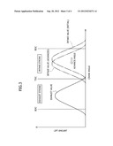
[0024] FIG. 3 is a graph showing a relationship between intake valve lift amount, exhaust valve lift amount, and crank angle, in the first embodiment of the present invention; and
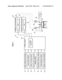
[0025] FIG. 4 is a system diagram of an internal combustion engine, in a second embodiment of the present invention.
DETAILED DESCRIPTION
[0026] Hereunder, embodiments of the present invention will be explained in detail based on the drawings.
[0027] FIG. 1 to FIG. 3 show a first embodiment of the present invention.
[0028] FIG. 2 shows a variable valve mechanism control apparatus 1 of an internal combustion engine 21.
[0029] This variable valve mechanism control apparatus 1, as shown in FIG. 2, is provided with a variable valve mechanism (also referred to as "variable valve timing mechanism" or "VVT mechanism") 2 for changing the phase of the operating angle which determines lift timing of an intake valve 22, and a control device 3 for controlling the variable valve mechanism 2 to change the phase when predetermined operating conditions are established.
[0030] This control device 3 has a VVT control function for changing the phase of the variable valve mechanism 2 in a case in which various types of signals are input and predetermined operating conditions are established.
[0031] Moreover, the variable valve mechanism control apparatus 1 is provided with a water temperature sensor 4, a crank angle sensor 5, an intake cam angle sensor 6, a throttle and accelerator opening sensor 7, an atmospheric pressure sensor 8, and an intake pressure sensor 9, on the input side of the control device 3.
[0032] Here, the water temperature sensor 4 detects the temperature of cooling water to detect the temperature of the internal combustion engine 21.
[0033] The crank angle sensor 5 detects a crank angle.
[0034] The intake cam angle sensor 6 detects the phase of an intake cam shaft 24.
[0035] The throttle and accelerator opening sensor 7 detects accelerator opening.
[0036] The atmospheric pressure sensor 8 detects atmospheric pressure.
[0037] The intake pressure sensor 9 detects intake negative pressure (also referred to as "intake manifold internal pressure").
[0038] That is to say, the variable valve mechanism control apparatus 1 measures the temperature of the internal combustion engine 21, the accelerator opening, and the intake negative pressure as the predetermined operating conditions.
[0039] Moreover, in the variable valve mechanism control apparatus 1, the variable valve mechanism 2 is provided on the output side of the control device 3.
[0040] Furthermore, the variable valve mechanism control apparatus 1 has a configuration such that when the measured temperature of the internal combustion engine 21 is greater than a certain value which can be treated as a post-warm-up state, the measured accelerator opening is less than a certain value which can be treated as an idling state, and the measured intake negative pressure is less than a predetermined value, the operating angle phase of the intake valve 22 is changed so as to converge to a predetermined phase at which a predetermined intake negative pressure occurs.
[0041] To describe in detail, the variable valve mechanism control apparatus 1 determines whether or not the measured temperature of the internal combustion engine 21 is greater than a certain value which can be treated as a post warm-up state, that is, whether or not a temperature T of the cooling water measured by the water temperature sensor 4 is greater than a certain value t, which serves as a temperature condition.
[0042] Moreover, the variable valve mechanism control apparatus 1 determines whether or not the measured accelerator opening is less than a certain value which can be treated as an idling state, that is, whether or not an accelerator opening A measured by the throttle accelerator opening sensor is less than a certain value a, which serves as an accelerator opening condition.
[0043] Furthermore, the variable valve mechanism control apparatus 1 determines whether or not the measured intake negative pressure is less than a predetermined value, that is, whether or not the intake negative pressure P_A-P_I measured by the intake pressure sensor 9 is less than a predetermined value p, which serves as a negative pressure condition. At this time, the intake negative pressure P_A-P_I is calculated by subtracting the intake manifold inner pressure P_I from the atmospheric pressure P_A.
[0044] Moreover, the variable valve mechanism control apparatus 1 changes the operating angle phase of the intake valve 22 so as to converge to a predetermined phase at which a predetermined intake negative pressure occurs, when the temperature T of the cooling water is greater than a certain value t, the accelerator opening A is less than a certain value a, and the intake negative pressure P_A-P_I is less than the predetermined value p.
[0045] Consequently, when the intake negative pressure is low in an idling state after the internal combustion engine 21 has undergone a warm-up operation, the intake negative pressure is increased by control of the variable valve mechanism 2. Therefore operations of a brake device and accessories can be ensured. Furthermore, in other cases in which the intake negative pressure is high, the phase can be adjusted to meet requirements of fuel economy and requirements of emission gas purification performance, and superior fuel economy and operations of the brake device and accessories can both be ensured at the same time.
[0046] In addition, when the variable valve mechanism 2 is operated, the amount of intake air changes, and accordingly, the negative pressure within the intake manifold 25 changes.
[0047] Normally, the control target value of the variable valve mechanism 2 is set so as to lower the negative pressure in order to enhance fuel economy.
[0048] On the other hand, when the load on accessories, such as an air conditioner and alternator, is high, the brake negative pressure may become insufficient in some cases.
[0049] In order to prevent this, the brake negative pressure is ensured by changing the control target value of the variable valve mechanism 2 according to the negative pressure value measured by the intake pressure sensor 9 attached to the intake manifold 25.
[0050] Furthermore, in the variable valve mechanism control apparatus 1, the variable valve mechanism 2 is only provided for the intake valve 22.
[0051] That is to say, as shown in FIG. 2, this variable valve mechanism 2 is configured with an OCV (also referred to as an "oil control valve") 10 to provide an optimum valve timing (advance amount and delayed amount) for the intake valve 22.
[0052] Moreover, in the variable valve mechanism control apparatus 1, the predetermined phase at which a predetermined intake negative pressure occurs, is set at an intermediate advance angle position, at which position the intake negative pressure increases, and which position is defined by balance of intake negative pressure reduction associated with blowback, which increases as the operating angle phase of the intake valve 22 is delayed, and intake negative pressure reduction due to an increase in internal EGR associated with valve overlap with an exhaust valve 23, which increases as the operating angle phase of the intake valve 22 is advanced.
[0053] Consequently, regardless of the closure timing of the exhaust valve 23, even when the opening angle of the intake valve 22 is set greater than crank angle 180 degrees, the phase can be converged at a position where intake negative pressure is the highest while blowback and internal EGR are balanced.
[0054] That is to say, if the operating angle phase of the intake valve 22 is delayed and valve closure timing is delayed, the amount of intake blowback increases, and if the amount of intake blowback increases, the intake negative pressure decreases. On the other hand, if the operating angle phase of the intake valve 22 is advanced and valve opening timing is accelerated, valve overlap increases, and consequently, internal EGR increases. Accordingly, if internal EGR increases, the intake negative pressure decreases.
[0055] In this manner, the amount of intake blowback changes to decrease with respect to an advance angle change in the operating angle phase of the intake valve 22. However, since the internal EGR changes to increase, the intake negative pressure takes a peak value at a predetermined phase, and even if it is advanced from the predetermined phase or it is delayed from the predetermined phase, the intake negative pressure decreases.
[0056] Accordingly, when the intake negative pressure P_A-P_I is lower than the predetermined value p, the control device 3 sets an intermediate phase position, at which the intake negative pressure becomes highest, as a target, within the phase variable range of the variable valve mechanism 2.
[0057] In addition, in the internal combustion engine 21 provided with the variable valve mechanism control apparatus 1, as shown in FIG. 3, the variable valve mechanism 2 shifts the timing of the valve opening and closing to the advance angle side from the reference initial position.
[0058] Furthermore, there is used the variable valve mechanism 2 in which the operating angle of the intake valve is set to an angle greater than 180 degrees, which corresponds to a piston intake stroke (for example, an angle approximately 10% to 40% greater than 180 degrees).
[0059] Moreover, the internal combustion engine 21 is such that, in an idling state in which the accelerator opening A is less than a certain value a, the intake valve 22 is set so as to close at a later timing, that is to say, the intake valve 22 is set to close at a timing later than bottom dead center. As a result, a predetermined amount of gas at the intake valve 22 to be drawn into the combustion chamber is returned to the intake manifold 25 side while the piston is rising to perform a compression stroke, that is to say, pumping loss is reduced by blowback. Accordingly, the intake negative pressure is reduced.
[0060] As shown in FIG. 3, by shifting the timing of the valve opening and closing to the advance angle direction, that is, to the direction in which the intake valve 22 closes earlier, blowback can be reduced and negative pressure can be ensured. That is to say, in order to ensure negative pressure, the operating angle of the variable valve mechanism 2 is shifted to the advance angle direction, that is, the direction in which the intake valve closes earlier.
[0061] On the other hand, if the advancing progresses and the opening timing of the intake valve 22 becomes earlier than the closure timing of the exhaust valve 23, valve overlap occurs. When valve overlap increases, internal EGR (exhaust gas remaining in the combustion chamber as a result of being accumulated or drawn again) increases as a result. Internal EGR refers to exhaust gas which remains in the combustion chamber as a result of being drawn again from the exhaust gas port into the combustion chamber, or being accumulated within the combustion chamber.
[0062] The pressure of the exhaust gas is relatively higher than the intake pipe internal pressure. Therefore, if advancing is carried out excessively, the intake negative pressure decreases excessively as a result of gas flow and pressure mutually influencing each other.
[0063] Here, there is set an intermediate advance angle position, at which intake negative pressure increases, and which position is defined by a balance between intake negative pressure reduction associated with blowback, which increases as closure timing of the intake valve 22 is delayed to exceed bottom dead center, and intake negative pressure reduction due to an increase in internal EGR associated with an increase in valve overlap, which increases with respect to the exhaust valve 23 as the operating angle phase of the intake valve 22 advances, that is, an intermediate advance angle position, at which intake negative pressure increases and which position is defined at a position in a valley between them, which are in a trade-off relationship, to thereby operate the variable valve mechanism 2 so that the timing of the valve opening and closing converges at this position.
[0064] Therefore, the amount of advance angle greatly depends on the specification of individual engines, and in order to determine setting for a unique advance angle amount for an individual engine, it is necessary to preliminarily ascertain the correlation between advance angle amount and negative pressure through experiments.
[0065] During a warm-up operation while engine temperature is low, for example the controllability of the variable valve mechanism 2 may not be sufficiently ensured in some cases. On the other hand, by performing fast idle control for completing the warm-up operation earlier, the amount of air intake and the amount of fuel injection are corrected to increase. Therefore, in this type of situation, it is preferable that this control for ensuring negative pressure not be performed.
[0066] Since intake negative pressure increases as it approaches the absolute pressure zero where the atmospheric pressure is taken as a reference, intake negative pressure P_A-P_I being less than a predetermined value p signifies intake negative pressure P_A-P_I being closer to the atmospheric pressure than to the predetermined value p.
[0067] Furthermore, in an idling operation state of the internal combustion engine 21 in which the accelerator opening A is less than a set opening a, closure timing of the intake valve 22 is set at a timing later than bottom dead center. Due to this valve closure timing setting, there occurs blowback in which the air drawn into the cylinder during an intake stroke with the piston descending, returns to the intake system during a compression stroke with the piston rising. As a result, the pumping loss is reduced while the intake negative pressure decreases.
[0068] Here, from the setting of the valve timing in the above idling operation, if the operation angle phase of the intake valve 22 is changed to advance as shown in FIG. 3, to thereby make the closure timing of the intake valve 22 earlier, the amount of air returned to the intake system during a compression stroke is reduced, and hence the intake negative pressure increases. That is to say, in response to a request for an intake negative pressure increase, the control device 3 changes the operating angle phase of the intake valve 22 to the advance angle direction, so as to close the intake valve 22 earlier.
[0069] However, if the amount of advance angle of the operating angle phase of the intake valve 22 is increased, valve opening timing of the intake valve 22 becomes earlier, so that valve overlap increases. Moreover if valve overlap increases, the amount of exhaust gas to be returned into the cylinder during the valve overlap period, among the exhaust gas discharged to the exhaust gas port, is increased, and the amount of new drawn air relatively decreases, so that intake negative pressure decreases.
[0070] That is to say, it is not that intake negative pressure increases as the valve timing is advanced from the valve timing setting for the intake valve 22 at the time of an idling state, but it is that although intake negative pressure increases initially with respect to the change of this advancing, intake negative pressure starts along the way to decrease with respect to the change of this advancing.
[0071] Consequently, the control device 3 takes the valve timing where the intake negative pressure becomes the highest, as a target, and advances the operating angle phase of the intake valve 22, so that the intake negative pressure P_A-P_I becomes higher than the predetermined value p.
[0072] When the intake negative pressure P_A-P_I is lower than the predetermined value p, the control device 3 gradually advances the operating angle phase of the intake valve 22, and takes the phase when the intake negative pressure P_A-P_I starts to exhibit change of decreasing with respect to the advance angle change of the phase, as the advance angle limit, and further advance angle control can be stopped.
[0073] Moreover, the control device 3 gradually increases the amount of advance angle of the operating angle phase of the intake valve 22, and it can stop advance angle control of the phase at the time that the intake negative pressure P_A-P_I has increased to the vicinity of the predetermined value p.
[0074] Furthermore, the control device 3 determines whether the direction of increasing change in intake negative pressure is the delay direction or advancement direction, based on the direction of change in intake negative pressure when the phase is advanced for example, and then it can gradually change the phase along the direction of increasing change in intake negative pressure.
[0075] Next, operation will be described, with reference to the flow chart for control of the variable valve mechanism control apparatus 1 illustrated in FIG. 1.
[0076] When the control program of this variable valve mechanism control apparatus 1 starts in a step (101), the process proceeds to a step (102) in which it is determined whether or not the measured temperature of the internal combustion engine is greater than a certain value which can be treated as a post-warm-up state, that is, whether or not the temperature T of cooling water measured by the water temperature sensor 4 is greater than a certain value t.
[0077] If the determination of whether this temperature T of cooling water measured by the water temperature sensor 4 is greater than the certain value t in the step (102) is NO, the process proceeds to a step (106) in which the control program of the variable valve mechanism control apparatus 1 described later is stopped (stop state which is also referred to as the "end state").
[0078] If the determination of whether this temperature T of cooling water measured by the water temperature sensor 4 is greater than the certain value t in the step (102) is YES, the process proceeds to a step (103) in which whether or not the measured accelerator opening is less than a certain value which can be treated as an idling state is measured, that is, whether or not the accelerator opening A measured by the throttle and accelerator opening sensor 7 is less than a certain value a is determined.
[0079] If the determination of whether the accelerator opening A is less than a certain value a in the step (103) is NO, the process proceeds to the step (106) of the control program of the variable valve mechanism control apparatus 1.
[0080] If the determination of whether the accelerator opening A is less than a certain value a in the step (103) is YES, the process proceeds to a step (104) in which whether or not the measured intake negative pressure is less than a predetermined value is measured, that is, whether or not the intake negative pressure P_A-P_I measured by the intake pressure sensor 9 is less than a predetermined value p is determined.
[0081] If the determination of whether the intake negative pressure P_A-P_I measured by the intake pressure sensor 9 is less than a predetermined value p in the step (104) is NO, the process proceeds to the step (106) (stop state) in which the control program of the variable valve control apparatus 1 is stopped.
[0082] If the determination of whether the intake negative pressure P_A-P_I measured by the intake pressure sensor 9 is less than a predetermined value p in the step (104) is YES, the process proceeds to a step (105) in which a control signal is output from the control device 3 to the variable valve mechanism 2, and the OCV 10 is operated to change the valve timing, and after this step (105), the process proceeds to the step (106) (stop state) in which the control program of the variable valve mechanism control apparatus 1 is stopped.
[0083] FIG. 4 shows a second embodiment of the present invention.
[0084] This second embodiment is described with elements which serve the same functions as those of the first embodiment being given the same reference signs.
[0085] This feature of this second embodiment is that variable valve mechanisms 12 and 16 of a variable valve mechanism control apparatus 11 of an internal combustion 21 are provided for an intake valve 22 and an exhaust valve 23, respectively.
[0086] That is to say, as shown in FIG. 4, the variable valve mechanism control apparatus 11 is provided with a water temperature sensor 4, a crank angle sensor 5, an intake cam angle sensor 6, a throttle and accelerator opening sensor 7, an atmospheric pressure sensor 8, an intake pressure sensor 9, and an exhaust cam angle sensor 14, on an input side of a control device 13.
[0087] The exhaust cam angle sensor 14 measured the phase of an exhaust cam shaft 26.
[0088] Moreover, as shown in FIG. 4, the variable valve mechanism 12 is provided with an OCV (may be referred to as an "oil control valve") 10 to provide an optimum valve timing for the intake valve 22, and the variable valve mechanism 16 is provided with an OCV (may be referred to as an "oil control valve") 15 to provide an optimum valve timing for the exhaust valve 23.
[0089] Here, as the operating angle phase of the exhaust valve 23 is advanced, valve overlap with the intake valve 22 decreases, and as valve overlap decreases, internal EGR decreases and the intake negative pressure increases. Consequently, the variable valve mechanism control apparatus takes the predetermined phase at which a predetermined intake negative pressure occurs, as the most advanced angle position of the operating angle phase of the exhaust valve 23.
[0090] Therefore, even if the operating angle phase of the intake valve 22 changes in various ways, the influence from these control states is unlikely to be received, and it is possible to substantially stably increase intake negative pressure.
[0091] Moreover, since only the OCV 15 of the variable valve mechanism 16 is controlled, control is simple and the computational load is low, so that control stability can be ensured.
[0092] In addition, also negative pressure may be ensured by shifting the operating angle phase of the exhaust valve 23 in some cases, depending on the specification of the internal combustion engine 21 and the operating state of the variable valve mechanisms 12 and 16.
[0093] The variable valve mechanism 16 shifts the operating angle phase of the exhaust valve 23 to the delayed angle side from the initial position serving as a reference. This is opposite of the variable valve mechanism 12, which shifts the operating angle phase from the initial position serving as a reference to the advance angle side. In those cases in which the operating angle phase of the exhaust valve 23 is shifted to the delayed angle side when the internal combustion engine is operated in an idling state due to fuel economy requirements or the like, negative pressure can be increased by advancing the operating angle phase so that it returns to the initial position direction.
[0094] Furthermore, in the case of this internal combustion engine 21, the highest negative pressure is observed at the most advanced angle position (initial position) of the operating angle phase of the exhaust valve 23. A VVT position at which the highest negative pressure unique to the internal combustion engine 21 is observed may be identified and set. If a plurality of these positions is present, it may be set in consideration of responsiveness at the time of shifting from VVT control based on other conditions.
[0095] The present invention is not limited by the first and second embodiments described above, and various applications and modifications may be made.
[0096] For example, in the case of a vehicle which does not employ a pressure sensor, there may be provided a special configuration in which intake manifold pressure estimated from the actual flow rate measured using an airflow sensor is employed.
[0097] Moreover, there may be provided a special configuration in which target value change of the variable valve mechanism is limited to just the idling operation state, and thereby the requirement for fuel economy in a traveling state and the requirement for negative pressure necessary in an idling state can both be satisfied.
[0098] Furthermore, in a vehicle in which brake booster pressure can be measured, there may be provided a special configuration in which brake booster pressure is employed instead of intake manifold internal pressure, and thereby changes limited to brake requirements can be made to the VVT target value.
[0099] Although the invention herein has been described with reference to particular embodiments, it is to be understood that these embodiments are merely illustrative of the principles and applications of the present invention. It is therefore to be understood that numerous modifications may be made to the illustrative embodiments and that other arrangements may be devised without departing from the spirit and scope of the present invention as defined by the appended claims.
User Contributions:
Comment about this patent or add new information about this topic:
Images included with this patent application:
 |  |
 |  |
 |
| Similar patent applications: | |
| Date | Title |
|---|---|
| 2012-11-22 | Portable handheld work apparatus having an internal combustion engine |
| 2012-01-12 | Control apparatus for internal combustion engine |
| 2012-05-24 | Control apparatus for internal combustion engine |
| 2012-10-25 | Valve apparatus for an internal combustion engine |
| 2012-11-22 | Control apparatus and control method for internal combusion engine |
| New patent applications in this class: | |
| Date | Title |
|---|---|
| 2018-01-25 | Split axial cam shifting system variable valve actuation functions |
| 2016-12-29 | Motor vehicle, control unit and method for controlling a phase angle of a camshaft |
| 2016-12-29 | Valve timing control device for internal combustion engine and controller for valve timing control device |
| 2016-12-29 | Apparatus for opening and closing channel |
| 2016-12-29 | Rotation control apparatus of cvvt |
| Top Inventors for class "Internal-combustion engines" | |
| Rank | Inventor's name |
|---|---|
| 1 | Ross Dykstra Pursifull |
| 2 | Gopichandra Surnilla |
| 3 | Joseph Norman Ulrey |
| 4 | Thomas G. Leone |
| 5 | Chris Paul Glugla |