Patent application title: CLUTCH FUNCTION DEVICE STRUCTURED WTIH CONTROLLABLE EPICYCLE GEAR SET
Inventors:
Tai-Her Yang (Dzan-Hwa, TW)
IPC8 Class: AF16H128FI
USPC Class:
475 13
Class name: Planetary gear transmission systems or components reversal of direction of power flow changes power transmission to alternate path input and output exchange functions
Publication date: 2012-08-30
Patent application number: 20120220404
Abstract:
The present invention relates to a clutch function device structured with
a controllable epicycle gear set (EG101), which is driven by a rotary
kinetic energy source and combined with a controllable brake device;
through controlling the controllable brake device to perform brake
locking or releasing, the operations of transmission function of
combining transmission or releasing between a rotation shaft (S101) at an
output/input end, a rotation shaft (S102) at an output/input end and a
sleeve type rotation shaft (AS101) of the epicycle gear set (EG101) are
enabled to be controlled.Claims:
1. A clutch function device structured with a controllable epicycle gear
set, wherein a rotation shaft (S101) combined with an input wheel (W101)
of an epicycle gear set (EG101) is served as an output/input end, and a
rotation shaft (S102) combined with an output wheel (W102) is served as
an output/input end, and a rocker arm (A101) and a sleeve type rotation
shaft (AS101) linked by the epicycle wheels (W103) are served as an
output/input end, so that a part or all of the three output/input ends
are respectively combined to one action side of a corresponding
controllable brake device, and the other action side of the controllable
brake device is connected to a housing (H100); through controlling the
controllable brake device to perform brake locking or releasing, the
operations of transmission function of combining transmission or
releasing between the rotation shaft (S101) at the output/input end, the
rotation shaft (S102) at the output/input end and the sleeve type
rotation shaft (AS101) of the epicycle gear set (EG101) are enabled to be
controlled; Epicycle gear set (EG101): constituted by an input wheel
(W101) and an output wheel (W102) and at least an epicycle wheel (W103),
and including through the bevel gears engaging with each other, or the
bevel friction wheels mutually performing friction transmissions to form
the epicycle gear set function, and also constituted by the rotation
shaft (S101), the rotation shaft (S102), the rocker arm (A101), the
sleeve type rotation shaft (AS101) and a bearing, as well as installed
with a shell for being combined in the housing (H100); The speed ratios
of the input wheel (W101) and the output wheel (W102) of the mentioned
epicycle gear set (EG101) are the same, and the speed ratios between the
above two and the epicycle wheel (W103) can be the same or different; or
The speed ratios of the input wheel (W101) and the output wheel (W102) of
the mentioned epicycle gear set (EG101) are different, the speed ratios
between the epicycle wheel (W103) and the output wheel (W102) can be the
same or different, and the speed ratios between the epicycle wheel (W103)
and the input wheel (W101) can be the same or different; Rocker arm
(A101): having one end provided for allowing the epicycle wheel (W103) to
rotate and link, and the other end axially extending toward one or both
of the rotation shaft (S101) and the rotation shaft (S102), and combined
to the sleeve type rotation shaft (AS101) for being sleeved on one or
both of the rotation shaft (S101) and the rotation shaft (S102) and
capable of rotating thereon; Controllable brake device (BK101):
constituted by a brake device controlled by a manual force or mechanical
force or hydraulic force or pneumatic force or electromagnetic force, and
having two controllable action sides for the operations of a brake
locking state for engagement or a releasing state for separation, wherein
one of the action sides is combined with the sleeve type rotation shaft
(AS101) or the rocker arm (A101), and the other action side is fixed in
the housing (H100); The shell of the epicycle gear set (EG101) is also
installed in the housing (H100), and the output wheel (W102) of the
epicycle gear set (EG101) is served to drive the rotation shaft (S102).
2. A clutch function device structured with a controllable epicycle gear set as claimed in claim 1, which is through controlling the controllable brake device (BK101) to perform brake locking or releasing, so as to enable the operation of clutch function between the rotation shaft (S101) and the rotation shaft (S102).
3. A clutch function device structured with a controllable epicycle gear set as claimed in claim 1, wherein the rocker arm (A101) and the sleeve type rotation shaft (AS101) linked by the epicycle wheels (W103) being served as an output/input end, and coaxially sleeved with the rotation shaft (S101) or the rotation shaft (S102), and the controllable brake device (BK102) being combined and fastened in the housing (H100) through the rotation shaft (S102), which mainly consists of: Epicycle gear set (EG101): constituted by an input wheel (W101) and an output wheel (W102) and at least an epicycle wheel (W103), and including through the bevel gears engaging with each other, or the bevel friction wheels mutually performing friction transmissions to form the epicycle gear set function, and also constituted by the rotation shaft (S101), the rotation shaft (S102), the rocker arm (A101), the sleeve type rotation shaft (AS101) and a bearing, as well as installed with a shell for being combined in the housing (H100); The speed ratios of the input wheel (W101) and the output wheel (W102) of the mentioned epicycle gear set (EG101) are the same, and the speed ratios between the above two and the epicycle wheel (W103) can be the same or different; or The speed ratios of the input wheel (W101) and the output wheel (W102) of the mentioned epicycle gear set (EG101) are different, the speed ratios between the epicycle wheel (W103) and the output wheel (W102) can be the same or different, and the speed ratios between the epicycle wheel (W103) and the input wheel (W101) can be the same or different; Rocker arm (A101): having one end provided for allowing the epicycle wheel (W103) to rotate and link, and the other end axially extending toward one or both of the rotation shaft (S101) and the rotation shaft (S102), and combined to the sleeve type rotation shaft (AS101) for being sleeved on one or both of the rotation shaft (S101) and the rotation shaft (S102) and capable of rotating thereon; Controllable brake device (BK102): constituted by a brake device controlled by a manual force or mechanical force or hydraulic force or pneumatic force or electromagnetic force, and having two controllable action sides for the operations of a brake locking state for engagement or a releasing state for separation, wherein one of the action sides is combined with the rotation shaft (S102), and the other action side is fixed in the housing (H100); The shell of the epicycle gear set (EG101) is also installed in the housing (H100), and the output wheel (W102) of the epicycle gear set (EG101) is served to drive the rotation shaft (S102).
4. A clutch function device structured with a controllable epicycle gear set as claimed in claim 3, which is through controlling the controllable brake device (BK102) to perform brake locking or releasing, so as to enable the operation of clutch function between the rotation shaft (S101) and the sleeve type rotation shaft (AS101).
5. A clutch function device structured with a controllable epicycle gear set as claimed in claim 1, wherein the rotation shaft (S102) serving to provide the output function is further installed with a controllable brake device (BK102) capable of preventing reverse linkage, which mainly consists of: Epicycle gear set (EG101): constituted by an input wheel (W101) and an output wheel (W102) and at least an epicycle wheel (W103), and including through the bevel gears engaging with each other, or the bevel friction wheels mutually performing friction transmissions to form the epicycle gear set function, and also constituted by the rotation shaft (S101), the rotation shaft (S102), the rocker arm (A101), the sleeve type rotation shaft (AS101) and a bearing, as well as installed with a shell for being combined in the housing (H100); The speed ratios of the input wheel (W101) and the output wheel (W102) of the mentioned epicycle gear set (EG101) are the same, and the speed ratios between the above two and the epicycle wheel (W103) can be the same or different; or The speed ratios of the input wheel (W101) and the output wheel (W102) of the mentioned epicycle gear set (EG101) are different, the speed ratios between the epicycle wheel (W103) and the output wheel (W102) can be the same or different, and the speed ratios between the epicycle wheel (W103) and the input wheel (W101) can be the same or different; Rocker arm (A101): having one end provided for allowing the epicycle wheel (W103) to rotate and link, and the other end axially extending toward one or both of the rotation shaft (S101) and the rotation shaft (S102), and combined to the sleeve type rotation shaft (AS101) for being sleeved on one or both of the rotation shaft (S101) and the rotation shaft (S102) and capable of rotating thereon; Controllable brake device (BK101): constituted by a brake device controlled by a manual force or mechanical force or hydraulic force or pneumatic force or electromagnetic force, and having two controllable action sides for the operations of a brake locking state for engagement or a releasing state for separation, wherein one of the action sides is combined with the sleeve type rotation shaft (AS101) or the rocker arm (A101), and the other action side is fixed in the housing (H100); Controllable brake device (BK102): constituted by a brake device controlled by a manual force or mechanical force or hydraulic force or pneumatic force or electromagnetic force, and having two controllable action sides for the operations of a brake locking state for engagement or a releasing state for separation, wherein one of the action sides is combined with the rotation shaft (S102), and the other action side is fixed in the housing (H100); The shell of the epicycle gear set (EG101) is also installed in the housing (H100), and the output wheel (W102) of the epicycle gear set (EG101) is served to drive the rotation shaft (S102).
6. A clutch function device structured with a controllable epicycle gear set as claimed in claim 5, which is through controlling the controllable brake device (BK101) and the controllable brake device (BK102) to generate one or more than one operation functions as following: 1) When the controllable brake device (BK101) is in a brake locking state, and the controllable brake device (BK102) is in a releasing state, the transmission relation between the rotation shaft (S101) and the rotation shaft (S102) is in a connecting relation allowing for transmission; 2) When the controllable brake device (BK101) is in the releasing state, and the controllable brake device (BK102) is in the brake locking state, the transmission relation between the rotation shaft (S101) and the sleeve type rotation shaft (AS101) is in a connecting relation allowing for transmission; 3) When the controllable brake device (BK101) and the controllable brake device (BK102) are both in the brake locking state, the rotation shaft (S101) and the rotation shaft (S102) and the sleeve type rotation shaft (AS101) are all connected in the brake locking state, thus not capable of mutually driving; 4) When the controllable brake device (BK101) and the controllable brake device (BK102) are both in the releasing state, the transmission relation between the rotation shaft (S101) and the rotation shaft (S102) and the sleeve type rotation shaft (AS101) is in a releasing relation allowing for idle rotation.
7. A clutch function device structured with a controllable epicycle gear set as claimed in claim 1, wherein the rotation shaft (S101) is further installed with a controllable brake device (BK103), so that the input wheel (W101) and the rotation shaft (S101) of the epicycle gear set (EG101) are served as an output/input end, the output wheel (W102) and the rotation shaft (S102) are served as an output/input end, and the epicycle wheels (W103) and the rocker arm (A101) and the sleeve type rotation shaft (AS101) linked by the epicycle wheels (W103) are sleeved on the rotation shaft (S101) or the rotation shaft (S102), and through the rocker arm (A101) or the sleeve type rotation shaft (AS101) connects to the controllable brake device (BK101) fastened in the housing (H100), and through the rotation shaft (S101) connects to the controllable brake device (BK103) fastened in the housing (H100), which mainly consists of: Epicycle gear set (EG101): constituted by an input wheel (W101) and an output wheel (W102) and at least an epicycle wheel (W103), and including through the bevel gears engaging with each other, or the bevel friction wheels mutually performing friction transmissions to form the epicycle gear set function, and also constituted by the rotation shaft (S101), the rotation shaft (S102), the rocker arm (A101), the sleeve type rotation shaft (AS101) and a bearing, as well as installed with a shell for being combined in the housing (H100); The speed ratios of the input wheel (W101) and the output wheel (W102) of the mentioned epicycle gear set (EG101) are the same, and the speed ratios between the above two and the epicycle wheel (W103) can be the same or different; or The speed ratios of the input wheel (W101) and the output wheel (W102) of the mentioned epicycle gear set (EG101) are different, the speed ratios between the epicycle wheel (W103) and the output wheel (W102) can be the same or different, and the speed ratios between the epicycle wheel (W103) and the input wheel (W101) can be the same or different; Rocker arm (A101): having one end provided for allowing the epicycle wheel (W103) to rotate and link, and the other end axially extending toward one or both of the rotation shaft (S101) and the rotation shaft (S102), and combined to the sleeve type rotation shaft (AS101) for being sleeved on one or both of the rotation shaft (S101) and the rotation shaft (S102) and capable of rotating thereon; Controllable brake device (BK101): constituted by a brake device controlled by a manual force or mechanical force or hydraulic force or pneumatic force or electromagnetic force, and having two controllable action sides for the operations of a brake locking state for engagement or a releasing state for separation, wherein one of the action sides is combined with the sleeve type rotation shaft (AS101) or the rocker arm (A101), and the other action side is fixed in the housing (H100); Controllable brake device (BK103): constituted by a brake device controlled by a manual force or mechanical force or hydraulic force or pneumatic force or electromagnetic force, and having two controllable action sides for the operations of a brake locking state for engagement or a releasing state for separation, wherein one of the action sides is combined with the rotation shaft (S101), and the other action side is fixed in the housing (H100); The shell of the epicycle gear set (EG101) is also installed in the housing (H100), and the output wheel (W102) of the epicycle gear set (EG101) is served to drive the rotation shaft (S102).
8. A clutch function device structured with a controllable epicycle gear set as claimed in claim 7, which is through controlling the controllable brake device (BK101) and the controllable brake device (BK103) to generate one or more than one operation functions as following: 1) When the controllable brake device (BK101) is in a brake locking state, and the controllable brake device (BK103) is in a releasing state, the transmission relation between the rotation shaft (S101) and the rotation shaft (S102) is in a connecting relation allowing for transmission; 2) When the controllable brake device (BK101) is in the releasing state, and the controllable brake device (BK103) is in the brake locking state, the transmission relation between the rotation shaft (S102) and the sleeve type rotation shaft (AS101) is in a connecting relation allowing for transmission; 3) When the controllable brake device (BK101) and the controllable brake device (BK103) are both in the brake locking state, the rotation shaft (S101) and the rotation shaft (S102) and the sleeve type rotation shaft (AS101) are all connected in the brake locking state, thus not capable of mutually driving; 4) When the controllable brake device (BK101) and the controllable brake device (BK103) are both in the releasing state, the transmission relation between the rotation shaft (S101) and the rotation shaft (S102) and the sleeve type rotation shaft (AS101) is in a releasing relation allowing for idle rotation.
9. A clutch function device structured with a controllable epicycle gear set as claimed in claim 3, wherein the rotation shaft (S101) is further installed with a controllable brake device (BK103), so that the input wheel (W101) and the rotation shaft (S101) of the epicycle gear set (EG101) are served as an output/input end, the output wheel (W102) and the rotation shaft (S102) are served as an output/input end, and the epicycle wheels (W103) and the rocker arm (A101) and the sleeve type rotation shaft (AS101) linked by the epicycle wheels (W103) are sleeved on the rotation shaft (S101) or the rotation shaft (S102), and through the rotation shaft (S102) connects to the controllable brake device (BK102) fastened in the housing (H100), and through the rotation shaft (S101) connects to the controllable brake device (BK103) fastened in the housing (H100), which mainly consists of: Epicycle gear set (EG101): constituted by an input wheel (W101) and an output wheel (W102) and at least an epicycle wheel (W103), and including through the bevel gears engaging with each other, or the bevel friction wheels mutually performing friction transmissions to form the epicycle gear set function, and also constituted by the rotation shaft (S101), the rotation shaft (S102), the rocker arm (A101), the sleeve type rotation shaft (AS101) and a bearing, as well as installed with a shell for being combined in the housing (H100); The speed ratios of the input wheel (W101) and the output wheel (W102) of the mentioned epicycle gear set (EG101) are the same, and the speed ratios between the above two and the epicycle wheel (W103) can be the same or different; or The speed ratios of the input wheel (W101) and the output wheel (W102) of the mentioned epicycle gear set (EG101) are different, the speed ratios between the epicycle wheel (W103) and the output wheel (W102) can be the same or different, and the speed ratios between the epicycle wheel (W103) and the input wheel (W101) can be the same or different; Rocker arm (A101): having one end provided for allowing the epicycle wheel (W103) to rotate and link, and the other end axially extending toward one or both of the rotation shaft (S101) and the rotation shaft (S102), and combined to the sleeve type rotation shaft (AS101) for being sleeved on one or both of the rotation shaft (S101) and the rotation shaft (S102) and capable of rotating thereon; Controllable brake device (BK102): constituted by a brake device controlled by a manual force or mechanical force or hydraulic force or pneumatic force or electromagnetic force, and having two controllable action sides for the operations of a brake locking state for engagement or a releasing state for separation, wherein one of the action sides is combined with the rotation shaft (S102), and the other action side is fixed in the housing (H100); Controllable brake device (BK103): constituted by a brake device controlled by a manual force or mechanical force or hydraulic force or pneumatic force or electromagnetic force, and having two controllable action sides for the operations of a brake locking state for engagement or a releasing state for separation, wherein one of the action sides is combined with the rotation shaft (S101), and the other action side is fixed in the housing (H100); The shell of the epicycle gear set (EG101) is also installed in the housing (H100), and the output wheel (W102) of the epicycle gear set (EG101) is served to drive the rotation shaft (S102).
10. A clutch function device structured with a controllable epicycle gear set as claimed in claim 9, which is through controlling the controllable brake device (BK102) and the controllable brake device (BK103) to generate one or more than one operation functions as following: 1) When the controllable brake device (BK103) is in a brake locking state, and the controllable brake device (BK102) is in a releasing state, the transmission relation between the sleeve type rotation shaft (AS101) and the rotation shaft (S102) is in a connecting relation allowing for transmission; 2) When the controllable brake device (BK103) is in the releasing state, and the controllable brake device (BK102) is in the brake locking state, the transmission relation between the rotation shaft (S101) and the sleeve type rotation shaft (AS101) is in a connecting relation allowing for transmission; 3) When the controllable brake device (BK101) and the controllable brake device (BK102) are both in the brake locking state, the rotation shaft (S101) and the rotation shaft (S102) and the sleeve type rotation shaft (AS101) are all connected in the brake locking state, thus not capable of mutually driving; 4) When the controllable brake device (BK101) and the controllable brake device (BK102) are both in the releasing state, the transmission relation between the rotation shaft (S101) and the rotation shaft (S102) and the sleeve type rotation shaft (AS101) is in a releasing relation allowing for idle rotation.
11. A clutch function device structured with a controllable epicycle gear set as claimed in claim 5, wherein the rotation shaft (S101) is further installed with a controllable brake device (BK103), so that the input wheel (W101) and the rotation shaft (S101) of the epicycle gear set (EG101) are served as an output/input end, the output wheel (W102) and the rotation shaft (S102) are served as an output/input end, and the epicycle wheels (W103) and the rocker arm (A101) and the sleeve type rotation shaft (AS101) linked by the epicycle wheels (W103) are sleeved on the rotation shaft (S101) or the rotation shaft (S102), and through the rocker arm (A101) or the sleeve type rotation shaft (AS101) connects to the controllable brake device (BK101) fastened in the housing (H100), and through the rotation shaft (S102) connects to the controllable brake device (BK102) fastened in the housing (H100), and through the rotation shaft (S101) connects to the controllable brake device (BK103) fastened in the housing (H100), which mainly consists of: Epicycle gear set (EG101): constituted by an input wheel (W101) and an output wheel (W102) and at least an epicycle wheel (W103), and including through the bevel gears engaging with each other, or the bevel friction wheels mutually performing friction transmissions to form the epicycle gear set function, and also constituted by the rotation shaft (S101), the rotation shaft (S102), the rocker arm (A101), the sleeve type rotation shaft (AS101) and a bearing, as well as installed with a shell for being combined in the housing (H100); The speed ratios of the input wheel (W101) and the output wheel (W102) of the mentioned epicycle gear set (EG101) are the same, and the speed ratios between the above two and the epicycle wheel (W103) can be the same or different; or The speed ratios of the input wheel (W101) and the output wheel (W102) of the mentioned epicycle gear set (EG101) are different, the speed ratios between the epicycle wheel (W103) and the output wheel (W102) can be the same or different, and the speed ratios between the epicycle wheel (W103) and the input wheel (W101) can be the same or different; Rocker arm (A101): having one end provided for allowing the epicycle wheel (W103) to rotate and link, and the other end axially extending toward one or both of the rotation shaft (S101) and the rotation shaft (S102), and combined to the sleeve type rotation shaft (AS101) for being sleeved on one or both of the rotation shaft (S101) and the rotation shaft (S102) and capable of rotating thereon; Controllable brake device (BK101): constituted by a brake device controlled by a manual force or mechanical force or hydraulic force or pneumatic force or electromagnetic force, and having two controllable action sides for the operations of a brake locking state for engagement or a releasing state for separation, wherein one of the action sides is combined with the sleeve type rotation shaft (AS101) or the rocker arm (A101), and the other action side is fixed in the housing (H100); The shell of the epicycle gear set (EG101) is also installed in the housing (H100), and the output wheel (W102) of the epicycle gear set (EG101) is served to drive the rotation shaft (S102); Controllable brake device (BK102): constituted by a brake device controlled by a manual force or mechanical force or hydraulic force or pneumatic force or electromagnetic force, and having two controllable action sides for the operations of a brake locking state for engagement or a releasing state for separation, wherein one of the action sides is combined with the rotation shaft (S102), and the other action side is fixed in the housing (H100); Controllable brake device (BK103): constituted by a brake device controlled by a manual force or mechanical force or hydraulic force or pneumatic force or electromagnetic force, and having two controllable action sides for the operations of a brake locking state for engagement or a releasing state for separation, wherein one of the action sides is combined with the rotation shaft (S101), and the other action side is fixed in the housing (H100).
12. A clutch function device structured with a controllable epicycle gear set as claimed in claim 11, which is through controlling the controllable brake device (BK101), the controllable brake device (BK102) and the controllable brake device (BK103) to generate one or more than one operation functions as following: 1) When the controllable brake device (BK101) is in a brake locking state, and the controllable brake device (BK102) and the controllable brake device (BK103) are in a releasing state, the transmission relation between the rotation shaft (S101) and the rotation shaft (S102) is in a connecting relation allowing for transmission; 2) When the controllable brake device (BK101) and the controllable brake device (BK103) are in the releasing state, and the controllable brake device (BK102) is in the brake locking state, the transmission relation between the rotation shaft (S101) and the sleeve type rotation shaft (AS101) is in a connecting relation allowing for transmission; 3) When the controllable brake device (BK103) is in the brake locking state, the controllable brake device (BK101) and the controllable brake device (BK102) are in the releasing state, the transmission relation between the sleeve type rotation shaft (AS101) and the rotation shaft (S102) is in a connecting relation allowing for transmission; 4) When two or more than two of the controllable brake device (BK101) and the controllable brake device (BK102) and the controllable brake device (BK103) are in the brake locking state, the rotation shaft (S101) and the rotation shaft (S102) and the sleeve type rotation shaft (AS101) are all connected in the brake locking state, thus not capable of mutually driving; 5) When the controllable brake device (BK101) and the controllable brake device (BK102) and the controllable brake device (BK103) are all in the releasing state, the transmission relation between the rotation shaft (S101) and the rotation shaft (S102) and the sleeve type rotation shaft (AS101) is in a releasing relation allowing for idle rotation.
Description:
BACKGROUND OF THE INVENTION
[0001] (a) Field of the Invention
[0002] The present invention relates to a clutch function device structured with a controllable epicycle gear set (EG101), which is driven by a rotary kinetic energy source and combined with a controllable brake device; through controlling the controllable brake device to perform brake locking or releasing, the operations of transmission function of combining transmission or releasing between a rotation shaft (S101) at an output/input end, a rotation shaft (S102) at an output/input end and a sleeve type rotation shaft (AS101) of the epicycle gear set (EG101) are enabled to be controlled.
[0003] (b) Description of the Prior Art
[0004] Conventionally a friction type electromagnetic clutch device is often installed between the output/input end of a rotary kinetic energy source and a load; and through electrically charging or breaking the friction type electromagnetic clutch device to perform operations of combining or releasing, the rotary kinetic energy source and the load are enabled to be engaged or released. One primary disadvantage of the conventional arts is that the friction type electromagnetic clutch device is often remained with residual rotary torque during the releasing, which may cause the kinetic energy loss and the ineffective operation.
SUMMARY OF THE INVENTION
[0005] The present invention provides a clutch function device structured with a controllable epicycle gear set, wherein a rotation shaft (S101) combined with an input wheel (W101) of an epicycle gear set (EG101) is served as an output/input end, and a rotation shaft (S102) combined with an output wheel (W102) is served as an output/input end, and a rocker arm (A101) and a sleeve type rotation shaft (AS101) linked by the epicycle wheels (W103) are served as an output/input end, so that a part or all of the three output/input ends are respectively combined to one action side of a corresponding controllable brake device, and the other action side of the controllable brake device is connected to a housing (H100); through controlling the controllable brake device to perform brake locking or releasing, the operations of transmission function of combining transmission or releasing between the rotation shaft (S101) at the output/input end, the rotation shaft (S102) at the output/input end and the sleeve type rotation shaft (AS101) of the epicycle gear set (EG101) are enabled to be controlled.
BRIEF DESCRIPTION OF THE DRAWINGS
[0006] FIG. 1 is a schematic structural view showing the input wheel (W101) and the rotation shaft (S101) of the epicycle gear set (EG101) being served as an output/input end, the output wheel (W102) and the rotation shaft (S102) being served as an output/input end, the rocker arm (A101) and the sleeve type rotation shaft (AS101) linked by the epicycle wheels (W103) being sleeved on the rotation shaft (S101) or the rotation shaft (S102), and the controllable brake device (BK101) being fastened in the housing (H100) through the rocker arm (A101) and the sleeve type rotation shaft (AS101), according to one embodiment of the present invention.
[0007] FIG. 2 is a schematic structural view showing the rocker arm (A101) and the sleeve type rotation shaft (AS101) linked by the epicycle wheels (W103) being served as an output/input end, and coaxially sleeved with the rotation shaft (S101) or the rotation shaft (S102), and the controllable brake device (BK102) being combined and fastened in the housing (H100) through the rotation shaft (S102), according to one embodiment of the present invention.
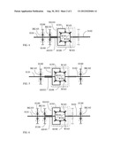
[0008] FIG. 3 is a schematic structural view showing the rotation shaft (S102) serving to provide the output function as shown in FIG. 1 being further installed with a controllable brake device (BK102) capable of preventing reverse linkage.
[0009] FIG. 4 is a schematic structural view showing the rotation shaft (S101) as shown in FIG. 1 being further installed with a controllable brake device (BK103).
[0010] FIG. 5 is a schematic structural view showing the rotation shaft (S101) as shown in FIG. 2 being further installed with a controllable brake device (BK103).
[0011] FIG. 6 is a schematic structural view showing the rotation shaft (S101) as shown in FIG. 3 being further installed with a controllable brake device (BK103).
DESCRIPTION OF MAIN COMPONENT SYMBOLS
[0012] A101: Rocker arm
[0013] AS101: Sleeve type rotation shaft
[0014] BK101-BK102-BK103: Controllable brake device
[0015] EG101: Epicycle gear set
[0016] H100: Housing
[0017] S101-S102: Rotation shaft
[0018] W101: Input wheel
[0019] W102: Output wheel
[0020] W103: Epicycle wheel
DETAILED DESCRIPTION OF THE PREFERRED EMBODIMENTS
[0021] Conventionally a friction type electromagnetic clutch device is often installed between the output/input end of a rotary kinetic energy source and a load; and through electrically charging or breaking the friction type electromagnetic clutch device to perform operations of combining or releasing, the rotary kinetic energy source and the load are enabled to be engaged or released. One primary disadvantage of the conventional arts is that the friction type electromagnetic clutch device is often remained with residual rotary torque during the releasing, which may cause the kinetic energy loss and the ineffective operation.
[0022] The present invention provides a clutch function device structured with a controllable epicycle gear set, wherein a rotation shaft (S101) combined with an input wheel (W101) of an epicycle gear set (EG101) is served as an output/input end, and a rotation shaft (S102) combined with an output wheel (W102) is served as an output/input end, and a rocker arm (A101) and a sleeve type rotation shaft (AS101) linked by the epicycle wheels (W103) are served as an output/input end, so that a part or all of the three output/input ends are respectively combined to one action side of a corresponding controllable brake device, and the other action side of the controllable brake device is connected to a housing (H100); through controlling the controllable brake device to perform brake locking or releasing, the operations of transmission function of combining transmission or releasing between the rotation shaft (S101) at the output/input end, the rotation shaft (S102) at the output/input end and the sleeve type rotation shaft (AS101) of the epicycle gear set (EG101) are enabled to be controlled;
[0023] The structure application of the clutch function device structured with a controllable epicycle gear set of present invention is disclosed as following:
[0024] FIG. 1 is a schematic structural view showing the input wheel (W101) and the rotation shaft (S101) of the epicycle gear set (EG101) being served as an output/input end, the output wheel (W102) and the rotation shaft (S102) being served as an output/input end, the epicycle wheels (W103) and the rocker arm (A101) and the sleeve type rotation shaft (AS101) linked by the epicycle wheels (W103) being sleeved on the rotation shaft (S101) or the rotation shaft (S102), and through the rocker arm (A101) or the sleeve type rotation shaft (AS101) connecting to the controllable brake device (BK101) fastened in the housing (H100), according to one embodiment of the present invention.
[0025] As show in FIG. 1, which mainly consists of: [0026] Epicycle gear set (EG101): constituted by an input wheel (W101) and an output wheel (W102) and at least an epicycle wheel (W103), and including through the bevel gears engaging with each other, or the bevel friction wheels mutually performing friction transmissions to form the epicycle gear set function, and also constituted by the rotation shaft (S101), the rotation shaft (S102), the rocker arm (A101), the sleeve type rotation shaft (AS101) and a bearing, as well as installed with a shell for being combined in the housing (H100);
[0027] The speed ratios of the input wheel (W101) and the output wheel (W102) of the mentioned epicycle gear set (EG101) are the same, and the speed ratios between the above two and the epicycle wheel (W103) can be the same or different; or
[0028] The speed ratios of the input wheel (W101) and the output wheel (W102) of the mentioned epicycle gear set (EG101) are different, the speed ratios between the epicycle wheel (W103) and the output wheel (W102) can be the same or different, and the speed ratios between the epicycle wheel (W103) and the input wheel (W101) can be the same or different; [0029] Rocker arm (A101): having one end provided for allowing the epicycle wheel (W103) to rotate and link, and the other end axially extending toward one or both of the rotation shaft (S101) and the rotation shaft (S102), and combined to the sleeve type rotation shaft (AS101) for being sleeved on one or both of the rotation shaft (S101) and the rotation shaft (S102) and capable of rotating thereon; [0030] Controllable brake device (BK101): constituted by a brake device controlled by a manual force or mechanical force or hydraulic force or pneumatic force or electromagnetic force, and having two controllable action sides for the operations of a brake locking state for engagement or a releasing state for separation, wherein one of the action sides is combined with the sleeve type rotation shaft (AS101) or the rocker arm (A101), and the other action side is fixed in the housing (H100); [0031] The shell of the epicycle gear set (EG101) is also installed in the housing (H100), and the output wheel (W102) of the epicycle gear set (EG101) is served to drive the rotation shaft (S102);
[0032] The clutch function device structured with a controllable epicycle gear set as shown in FIG. 1 is through controlling the controllable brake device (BK101) to perform brake locking or releasing, so as to enable the operation of clutch function between the rotation shaft (S101) and the rotation shaft (S102).
[0033] FIG. 2 is a schematic structural view showing the rocker arm (A101) and the sleeve type rotation shaft (AS101) linked by the epicycle wheels (W103) being served as an output/input end, and coaxially sleeved with the rotation shaft (S101) or the rotation shaft (S102), and the controllable brake device (BK102) being combined and fastened in the housing (H100) through the rotation shaft (S102), according to one embodiment of the present invention.
[0034] As show in FIG. 2, it mainly consists of: [0035] Epicycle gear set (EG101): constituted by an input wheel (W101) and an output wheel (W102) and at least an epicycle wheel (W103), and including through the bevel gears engaging with each other, or the bevel friction wheels mutually performing friction transmissions to form the epicycle gear set function, and also constituted by the rotation shaft (S101), the rotation shaft (S102), the rocker arm (A101), the sleeve type rotation shaft (AS101) and a bearing, as well as installed with a shell for being combined in the housing (H100);
[0036] The speed ratios of the input wheel (W101) and the output wheel (W102) of the mentioned epicycle gear set (EG101) are the same, and the speed ratios between the above two and the epicycle wheel (W103) can be the same or different; or
[0037] The speed ratios of the input wheel (W101) and the output wheel (W102) of the mentioned epicycle gear set (EG101) are different, the speed ratios between the epicycle wheel (W103) and the output wheel (W102) can be the same or different, and the speed ratios between the epicycle wheel (W103) and the input wheel (W101) can be the same or different; [0038] Rocker arm (A101): having one end provided for allowing the epicycle wheel (W103) to rotate and link, and the other end axially extending toward one or both of the rotation shaft (S101) and the rotation shaft (S102), and combined to the sleeve type rotation shaft (AS101) for being sleeved on one or both of the rotation shaft (S101) and the rotation shaft (S102) and capable of rotating thereon; [0039] Controllable brake device (BK102): constituted by a brake device controlled by a manual force or mechanical force or hydraulic force or pneumatic force or electromagnetic force, and having two controllable action sides for the operations of a brake locking state for engagement or a releasing state for separation, wherein one of the action sides is combined with the rotation shaft (S102), and the other action side is fixed in the housing (H100); [0040] The shell of the epicycle gear set (EG101) is also installed in the housing (H100), and the output wheel (W102) of the epicycle gear set (EG101) is served to drive the rotation shaft (S102);
[0041] The clutch function device structured with a controllable epicycle gear set as shown in FIG. 2 is through controlling the controllable brake device (BK102) to perform brake locking or releasing, so as to enable the operation of clutch function between the rotation shaft (S101) and the sleeve type rotation shaft (AS101).
[0042] FIG. 3 is a schematic structural view showing the rotation shaft (S102) serving to provide the output function as shown in FIG. 1 being further installed with a controllable brake device (BK102) capable of preventing reverse linkage.
[0043] As show in FIG. 3, it mainly consists of: [0044] Epicycle gear set (EG101): constituted by an input wheel (W101) and an output wheel (W102) and at least an epicycle wheel (W103), and including through the bevel gears engaging with each other, or the bevel friction wheels mutually performing friction transmissions to form the epicycle gear set function, and also constituted by the rotation shaft (S101), the rotation shaft (S102), the rocker arm (A101), the sleeve type rotation shaft (AS101) and a bearing, as well as installed with a shell for being combined in the housing (H100);
[0045] The speed ratios of the input wheel (W101) and the output wheel (W102) of the mentioned epicycle gear set (EG101) are the same, and the speed ratios between the above two and the epicycle wheel (W103) can be the same or different; or
[0046] The speed ratios of the input wheel (W101) and the output wheel (W102) of the mentioned epicycle gear set (EG101) are different, the speed ratios between the epicycle wheel (W103) and the output wheel (W102) can be the same or different, and the speed ratios between the epicycle wheel (W103) and the input wheel (W101) can be the same or different; [0047] Rocker arm (A101): having one end provided for allowing the epicycle wheel (W103) to rotate and link, and the other end axially extending toward one or both of the rotation shaft (S101) and the rotation shaft (S102), and combined to the sleeve type rotation shaft (AS101) for being sleeved on one or both of the rotation shaft (S101) and the rotation shaft (S102) and capable of rotating thereon; [0048] Controllable brake device (BK101): constituted by a brake device controlled by a manual force or mechanical force or hydraulic force or pneumatic force or electromagnetic force, and having two controllable action sides for the operations of a brake locking state for engagement or a releasing state for separation, wherein one of the action sides is combined with the sleeve type rotation shaft (AS101) or the rocker arm (A101), and the other action side is fixed in the housing (H100); [0049] Controllable brake device (BK102): constituted by a brake device controlled by a manual force or mechanical force or hydraulic force or pneumatic force or electromagnetic force, and having two controllable action sides for the operations of a brake locking state for engagement or a releasing state for separation, wherein one of the action sides is combined with the rotation shaft (S102), and the other action side is fixed in the housing (H100); [0050] The shell of the epicycle gear set (EG101) is also installed in the housing (H100), and the output wheel (W102) of the epicycle gear set (EG101) is served to drive the rotation shaft (S102);
[0051] The clutch function device structured with a controllable epicycle gear set as shown in FIG. 3 is through controlling the controllable brake device (BK101) and the controllable brake device (BK102) to generate one or more than one operation functions as following: [0052] 1. When the controllable brake device (BK101) is in a brake locking state, and the controllable brake device (BK102) is in a releasing state, the transmission relation between the rotation shaft (S101) and the rotation shaft (S102) is in a connecting relation allowing for transmission; [0053] 2. When the controllable brake device (BK101) is in the releasing state, and the controllable brake device (BK102) is in the brake locking state, the transmission relation between the rotation shaft (S101) and the sleeve type rotation shaft (AS101) is in a connecting relation allowing for transmission; [0054] 3. When the controllable brake device (BK101) and the controllable brake device (BK102) are both in the brake locking state, the rotation shaft (S101) and the rotation shaft (S102) and the sleeve type rotation shaft (AS101) are all connected in the brake locking state, thus not capable of mutually driving; [0055] 4. When the controllable brake device (BK101) and the controllable brake device (BK102) are both in the releasing state, the transmission relation between the rotation shaft (S101) and the rotation shaft (S102) and the sleeve type rotation shaft (AS101) is in a releasing relation allowing idle rotation;
[0056] According to the clutch function device structured with a controllable epicycle gear set of present invention, the rotation shaft (S101) can be further installed with a controllable brake device (BK103) for increasing the controllable operation function, the disclosure is as following:
[0057] FIG. 4 is a schematic structural view showing the rotation shaft (S101) being further installed with a controllable brake device (BK103) according to the embodiment shown in FIG. 1.
[0058] As shown in FIG. 4, the input wheel (W101) and the rotation shaft (S101) of the epicycle gear set (EG101) are served as an output/input end, the output wheel (W102) and the rotation shaft (S102) are served as an output/input end, and the epicycle wheels (W103) and the rocker arm (A101) and the sleeve type rotation shaft (AS101) linked by the epicycle wheels (W103) are sleeved on the rotation shaft (S101) or the rotation shaft (S102), and through the rocker arm (A101) or the sleeve type rotation shaft (AS101) connects to the controllable brake device (BK101) fastened in the housing (H100), and through the rotation shaft (S101) connects to the controllable brake device (BK103) fastened in the housing (H100), and it mainly consists of: [0059] Epicycle gear set (EG101): constituted by an input wheel (W101) and an output wheel (W102) and at least an epicycle wheel (W103), and including through the bevel gears engaging with each other, or the bevel friction wheels mutually performing friction transmissions to form the epicycle gear set function, and also constituted by the rotation shaft (S101), the rotation shaft (S102), the rocker arm (A101), the sleeve type rotation shaft (AS101) and a bearing, as well as installed with a shell for being combined in the housing (H100);
[0060] The speed ratios of the input wheel (W101) and the output wheel (W102) of the mentioned epicycle gear set (EG101) are the same, and the speed ratios between the above two and the epicycle wheel (W103) can be the same or different; or
[0061] The speed ratios of the input wheel (W101) and the output wheel (W102) of the mentioned epicycle gear set (EG101) are different, the speed ratios between the epicycle wheel (W103) and the output wheel (W102) can be the same or different, and the speed ratios between the epicycle wheel (W103) and the input wheel (W101) can be the same or different; [0062] Rocker arm (A101): having one end provided for allowing the epicycle wheel (W103) to rotate and link, and the other end axially extending toward one or both of the rotation shaft (S101) and the rotation shaft (S102), and combined to the sleeve type rotation shaft (AS101) for being sleeved on one or both of the rotation shaft (S101) and the rotation shaft (S102) and capable of rotating thereon; [0063] Controllable brake device (BK101): constituted by a brake device controlled by a manual force or mechanical force or hydraulic force or pneumatic force or electromagnetic force, and having two controllable action sides for the operations of a brake locking state for engagement or a releasing state for separation, wherein one of the action sides is combined with the sleeve type rotation shaft (AS101) or the rocker arm (A101), and the other action side is fixed in the housing (H100); [0064] Controllable brake device (BK103): constituted by a brake device controlled by a manual force or mechanical force or hydraulic force or pneumatic force or electromagnetic force, and having two controllable action sides for the operations of a brake locking state for engagement or a releasing state for separation, wherein one of the action sides is combined with the rotation shaft (S101), and the other action side is fixed in the housing (H100); [0065] The shell of the epicycle gear set (EG101) is also installed in the housing (H100), and the output wheel (W102) of the epicycle gear set (EG101) is served to drive the rotation shaft (S102);
[0066] The clutch function device structured with a controllable epicycle gear set as shown in FIG. 4 is through controlling the controllable brake device (BK101) and the controllable brake device (BK103) to generate one or more than one operation functions as following: [0067] 1. When the controllable brake device (BK101) is in a brake locking state, and the controllable brake device (BK103) is in a releasing state, the transmission relation between the rotation shaft (S101) and the rotation shaft (S102) is in a connecting relation allowing for transmission; [0068] 2. When the controllable brake device (BK101) is in the releasing state, and the controllable brake device (BK103) is in the brake locking state, the transmission relation between the rotation shaft (S102) and the sleeve type rotation shaft (AS101) is in a connecting relation allowing for transmission; [0069] 3. When the controllable brake device (BK101) and the controllable brake device (BK103) are both in the brake locking state, the rotation shaft (S101) and the rotation shaft (S102) and the sleeve type rotation shaft (AS101) are all connected in the brake locking state, thus not capable of mutually driving; [0070] 4. When the controllable brake device (BK101) and the controllable brake device (BK103) are both in the releasing state, the transmission relation between the rotation shaft (S101) and the rotation shaft (S102) and the sleeve type rotation shaft (AS101) is in a releasing relation allowing idle rotation;
[0071] FIG. 5 is a schematic structural view showing the rotation shaft (S101) being further installed with a controllable brake device (BK103) according to the embodiment shown in FIG. 2
[0072] As shown in FIG. 5, the input wheel (W101) and the rotation shaft (S101) of the epicycle gear set (EG101) are served as an output/input end, the output wheel (W102) and the rotation shaft (S102) are served as an output/input end, and the epicycle wheels (W103) and the rocker arm (A101) and the sleeve type rotation shaft (AS101) linked by the epicycle wheels (W103) are sleeved on the rotation shaft (S101) or the rotation shaft (S102), and through the rotation shaft (S102) connects to the controllable brake device (BK102) fastened in the housing (H100), and through the rotation shaft (S101) connects to the controllable brake device (BK103) fastened in the housing (H100), which mainly consists of: [0073] Epicycle gear set (EG101): constituted by an input wheel (W101) and an output wheel (W102) and at least an epicycle wheel (W103), and including through the bevel gears engaging with each other, or the bevel friction wheels mutually performing friction transmissions to form the epicycle gear set function, and also constituted by the rotation shaft (S101), the rotation shaft (S102), the rocker arm (A101), the sleeve type rotation shaft (AS101) and a bearing, as well as installed with a shell for being combined in the housing (H100);
[0074] The speed ratios of the input wheel (W101) and the output wheel (W102) of the mentioned epicycle gear set (EG101) are the same, and the speed ratios between the above two and the epicycle wheel (W103) can be the same or different; or
[0075] The speed ratios of the input wheel (W101) and the output wheel (W102) of the mentioned epicycle gear set (EG101) are different, the speed ratios between the epicycle wheel (W103) and the output wheel (W102) can be the same or different, and the speed ratios between the epicycle wheel (W103) and the input wheel (W101) can be the same or different; [0076] Rocker arm (A101): having one end provided for allowing the epicycle wheel (W103) to rotate and link, and the other end axially extending toward one or both of the rotation shaft (S101) and the rotation shaft (S102), and combined to the sleeve type rotation shaft (AS101) for being sleeved on one or both of the rotation shaft (S101) and the rotation shaft (S102) and capable of rotating thereon; [0077] Controllable brake device (BK102): constituted by a brake device controlled by a manual force or mechanical force or hydraulic force or pneumatic force or electromagnetic force, and having two controllable action sides for the operations of a brake locking state for engagement or a releasing state for separation, wherein one of the action sides is combined with the rotation shaft (S102), and the other action side is fixed in the housing (H100); [0078] Controllable brake device (BK103): constituted by a brake device controlled by a manual force or mechanical force or hydraulic force or pneumatic force or electromagnetic force, and having two controllable action sides for the operations of a brake locking state for engagement or a releasing state for separation, wherein one of the action sides is combined with the rotation shaft (S101), and the other action side is fixed in the housing (H100); [0079] The shell of the epicycle gear set (EG101) is also installed in the housing (H100), and the output wheel (W102) of the epicycle gear set (EG101) is served to drive the rotation shaft (S102);
[0080] The clutch function device structured with a controllable epicycle gear set as shown in FIG. 5 is through controlling the controllable brake device (BK102) and the controllable brake device (BK103) to generate one or more than one operation functions as following: [0081] 1. When the controllable brake device (BK103) is in a brake locking state, and the controllable brake device (BK102) is in a releasing state, the transmission relation between the sleeve type rotation shaft (AS101) and the rotation shaft (S102) is in a connecting relation allowing for transmission; [0082] 2. When the controllable brake device (BK103) is in the releasing state, and the controllable brake device (BK102) is in the brake locking state, the transmission relation between the rotation shaft (S101) and the sleeve type rotation shaft (AS101) is in a connecting relation allowing for transmission; [0083] 3. When the controllable brake device (BK101) and the controllable brake device (BK102) are both in the brake locking state, the rotation shaft (S101) and the rotation shaft (S102) and the sleeve type rotation shaft (AS101) are all connected in the brake locking state, thus not capable of mutually driving; [0084] 4. When the controllable brake device (BK101) and the controllable brake device (BK102) are both in the releasing state, the transmission relation between the rotation shaft (S101) and the rotation shaft (S102) and the sleeve type rotation shaft (AS101) is in a releasing relation allowing for idle rotation;
[0085] According to the clutch function device structured with a controllable epicycle gear set of the present invention, the sleeve type rotation shaft (AS101) is installed with the controllable brake device (BK101) and the rotation shaft (S102) is installed with the controllable brake device (BK102), and the rotation shaft (S101) can be further installed with a controllable brake device (BK103) for increasing the controllable operation function.
[0086] FIG. 6 is a schematic structural view showing the rotation shaft (S101) being further installed with a controllable brake device (BK103) according to the embodiment shown in FIG. 3.
[0087] As shown in FIG. 6, the input wheel (W101) and the rotation shaft (S101) of the epicycle gear set (EG101) are served as an output/input end, the output wheel (W102) and the rotation shaft (S102) are served as an output/input end, and the epicycle wheels (W103) and the rocker arm (A101) and the sleeve type rotation shaft (AS101) linked by the epicycle wheels (W103) are sleeved on the rotation shaft (S101) or the rotation shaft (S102), and through the rocker arm (A101) or the sleeve type rotation shaft (AS101) connects to the controllable brake device (BK101) fastened in the housing (H100), and through the rotation shaft (S102) connects to the controllable brake device (BK102) fastened in the housing (H100), and through the rotation shaft (S101) connects to the controllable brake device (BK103) fastened in the housing (H100), which mainly consists of: [0088] Epicycle gear set (EG101): constituted by an input wheel (W101) and an output wheel (W102) and at least an epicycle wheel (W103), and including through the bevel gears engaging with each other, or the bevel friction wheels mutually performing friction transmissions to form the epicycle gear set function, and also constituted by the rotation shaft (S101), the rotation shaft (S102), the rocker arm (A101), the sleeve type rotation shaft (AS101) and a bearing, as well as installed with a shell for being combined in the housing (H100);
[0089] The speed ratios of the input wheel (W101) and the output wheel (W102) of the mentioned epicycle gear set (EG101) are the same, and the speed ratios between the above two and the epicycle wheel (W103) can be the same or different; or
[0090] The speed ratios of the input wheel (W101) and the output wheel (W102) of the mentioned epicycle gear set (EG101) are different, the speed ratios between the epicycle wheel (W103) and the output wheel (W102) can be the same or different, and the speed ratios between the epicycle wheel (W103) and the input wheel (W101) can be the same or different; [0091] Rocker arm (A101): having one end provided for allowing the epicycle wheel (W103) to rotate and link, and the other end axially extending toward one or both of the rotation shaft (S101) and the rotation shaft (S102), and combined to the sleeve type rotation shaft (AS101) for being sleeved on one or both of the rotation shaft (S101) and the rotation shaft (S102) and capable of rotating thereon; [0092] Controllable brake device (BK101): constituted by a brake device controlled by a manual force or mechanical force or hydraulic force or pneumatic force or electromagnetic force, and having two controllable action sides for the operations of a brake locking state for engagement or a releasing state for separation, wherein one of the action sides is combined with the sleeve type rotation shaft (AS101) or the rocker arm (A101), and the other action side is fixed in the housing (H100); [0093] The shell of the epicycle gear set (EG101) is also installed in the housing (H100), and the output wheel (W102) of the epicycle gear set (EG101) is served to drive the rotation shaft (S102); [0094] Controllable brake device (BK102): constituted by a brake device controlled by a manual force or mechanical force or hydraulic force or pneumatic force or electromagnetic force, and having two controllable action sides for the operations of a brake locking state for engagement or a releasing state for separation, wherein one of the action sides is combined with the rotation shaft (S102), and the other action side is fixed in the housing (H100); [0095] Controllable brake device (BK103): constituted by a brake device controlled by a manual force or mechanical force or hydraulic force or pneumatic force or electromagnetic force, and having two controllable action sides for the operations of a brake locking state for engagement or a releasing state for separation, wherein one of the action sides is combined with the rotation shaft (S101), and the other action side is fixed in the housing (H100);
[0096] The clutch function device structured with a controllable epicycle gear set as shown in FIG. 6 is through controlling the controllable brake device (BK101), the controllable brake device (BK102) and the controllable brake device (BK103) to generate one or more than one operation functions as following: [0097] 1. When the controllable brake device (BK101) is in a brake locking state, and the controllable brake device (BK102) and the controllable brake device (BK103) are in a releasing state, the transmission relation between the rotation shaft (S101) and the rotation shaft (S102) is in a connecting relation allowing for transmission; [0098] 2. When the controllable brake device (BK101) and the controllable brake device (BK103) are in the releasing state, and the controllable brake device (BK102) is in the brake locking state, the transmission relation between the rotation shaft (S101) and the sleeve type rotation shaft (AS101) is in a connecting relation allowing for transmission; [0099] 3. When the controllable brake device (BK103) is in the brake locking state, the controllable brake device (BK101) and the controllable brake device (BK102) are in the releasing state, the transmission relation between the sleeve type rotation shaft (AS101) and the rotation shaft (S102) is in a connecting relation allowing for transmission; [0100] 4. When two or more than two of the controllable brake device (BK101) and the controllable brake device (BK102) and the controllable brake device (BK103) are in the brake locking state, the rotation shaft (S101) and the rotation shaft (S102) and the sleeve type rotation shaft (AS101) are all connected in the brake locking state, thus not capable of mutually driving; [0101] 5. When the controllable brake device (BK101) and the controllable brake device (BK102) and the controllable brake device (BK103) are all in the releasing state, the transmission relation between the rotation shaft (S101) and the rotation shaft (S102) and the sleeve type rotation shaft (AS101) is a releasing relation allowing for idle rotation.
User Contributions:
Comment about this patent or add new information about this topic:
| People who visited this patent also read: | |
| Patent application number | Title |
|---|---|
| 20120221624 | Client Diversity Policy Sharing with the Transport Layer |
| 20120221623 | METHOD AND SYSTEM FOR INTEGRATING DATA FROM MULTIPLE SOURCES |
| 20120221622 | SYSTEM AND METHOD FOR UNLOCKING A DEVICE REMOTELY FROM A SERVER |
| 20120221621 | DISTRIBUTED SYSTEM, COMMUNICATION MEANS SELECTION METHOD, AND COMMUNICATION MEANS SELECTION PROGRAM |
| 20120221620 | APPARATUS, SYSTEM, AND METHOD FOR FACILITATING DATA FLOW BETWEEN A FIRST APPLICATION PROGRAMMING INTERFACE AND A SECOND APPLICATION PROGRAMMING INTERFACE |
Images included with this patent application:
 |  |
 |
| Similar patent applications: | |
| Date | Title |
|---|---|
| 2013-06-13 | Shifting device and gear unit |
| 2012-04-19 | Welded structure and welding method |
| 2010-01-07 | Dual clutch multi-speed transaxle |
| 2011-03-24 | Reconfigurable hybrid gear train |
| 2013-03-21 | Multiple-row epicyclic gear |
| Top Inventors for class "Planetary gear transmission systems or components" | |
| Rank | Inventor's name |
|---|---|
| 1 | James M. Hart |
| 2 | Scott H. Wittkopp |
| 3 | Andrew W. Phillips |
| 4 | Clinton E. Carey |
| 5 | Andrew W. Phillips |