Patent application title: Enhanced Surface Area Heat Pipe
Inventors:
Wesley Stephen Harper (Craig, CO, US)
IPC8 Class: AF28D1504FI
USPC Class:
16510426
Class name: Liquid fluent heat exchange material utilizing change of state utilizing capillary attraction
Publication date: 2012-07-12
Patent application number: 20120175085
Abstract:
A sealed thermal cycle heat transferring device having areas of gross
surface modification enabling efficiency enhancement through increased
working fluid capacity and reduced conduction resistance while still
retaining the net surface footprint. Certain embodiments of the present
invention facilitate surface enhancement affecting condensing portions as
well as evaporating portions. Thermal transfer performance remains
adjustable well beyond conventional heat pipe apparatus by allowance of
careful selection of surface enhancing parameters including diameter,
depth, shape, amount, area and location of surface enhancement.
Additional advantages may include the enhancement of mounting, attachment
and enablement of thermally generating, dissipating or regulating
components, devices, assemblies and any uses where the present invention
may benefit thermal addition, subtraction, regulation and transfer.Claims:
1. A thermal energy transfer apparatus comprising: a sealed enclosure,
fluid, fluid conduction means; and at least one enhanced surface area
heat transfer zone, wherein the process of thermal transference is
rendered more efficient.
2. The thermal energy transfer apparatus as recited in claim 1 wherein said enhanced surface area heat transfer zone being formed as a protruding area rising above or below the surface adjacent of said enhanced surface area heat transfer zone of said sealed enclosure.
3. The thermal energy transfer apparatus as recited in claim 1 wherein said enhanced surface area heat transfer zone being formed to a predetermined height or depth.
4. The thermal energy transfer apparatus as recited in claim 1 wherein said enhanced surface area heat transfer zone being formed to a predetermined outline.
5. The thermal energy transfer apparatus as recited in claim 1 wherein said enhanced surface area heat transfer zone being formed to a predetermined thickness.
6. The thermal energy transfer apparatus as recited in claim 1 wherein said fluid being selected from the group consisting of substances existing as a liquid at a predetermined energy state within said sealed enclosure.
7. The thermal energy transfer apparatus as recited in claim 1 wherein said fluid being selected from the group consisting of substances existing as a vapor at a predetermined energy state within said sealed enclosure.
8. The thermal energy transfer apparatus as recited in claim 1 wherein said fluid being selected from the group consisting of substances existing as a solid at a predetermined energy state within said sealed enclosure.
9. The thermal energy transfer apparatus as recited in claim 1 wherein said fluid conduction means further includes gravity assisted fluid conduction.
10. The thermal energy transfer apparatus as recited in claim 1 wherein said fluid conduction means further including selections from the group consisting of objects capable of capillary conduction.
11. A thermal energy transfer apparatus comprising: An adjustably sealed enclosure, fluid, fluid conduction means; and at least one enhanced surface area heat transfer zone, wherein the process of thermal transference is rendered more efficient.
12. The thermal energy transfer apparatus as recited in claim 11 wherein said enhanced surface area heat transfer zone being formed as a protruding area rising above or below the surface adjacent of said enhanced surface area heat transfer zone of said adjustably sealed enclosure.
13. The thermal energy transfer apparatus as recited in claim 11 wherein said enhanced surface area heat transfer zone being formed to a predetermined height or depth.
14. The thermal energy transfer apparatus as recited in claim 11 wherein said enhanced surface area heat transfer zone being formed to a predetermined outline.
15. The thermal energy transfer apparatus as recited in claim 11 wherein said enhanced surface area heat transfer zone being formed to a predetermined thickness.
16. The thermal energy transfer apparatus as recited in claim 11 wherein said fluid being selected from the group consisting of substances existing as a liquid at a predetermined energy state within said adjustably sealed enclosure.
17. The thermal energy transfer apparatus as recited in claim 11 wherein said fluid being selected from the group consisting of substances existing as a vapor at a predetermined energy state within said adjustably sealed enclosure.
18. The thermal energy transfer apparatus as recited in claim 11 wherein said fluid being selected from the group consisting of substances existing as a solid at a predetermined energy state within said adjustably sealed enclosure.
19. The thermal energy transfer apparatus as recited in claim 11 wherein said fluid conduction means further includes gravity assisted fluid conduction.
20. The thermal energy transfer apparatus as recited in claim 11 wherein said fluid conduction means further including selections from the group consisting of objects capable of capillary conduction.
Description:
CROSS-REFERENCE TO RELATED INVENTIONS
[0001] Claiming Benefit of provisional patent application filed by Wesley S. Harper on Jan. 7, 2011, application No. 61/430,909,
FEDERALLY SPONSORED RESEARCH
[0002] Not Applicable
SEQUENCE LISTING OR PROGRAM
[0003] Not Applicable
BACKGROUND OF THE INVENTION
[0004] 1. Field of Invention
[0005] This invention relates to heat transferring devices, more specifically to heat pipes.
[0006] 2. Background of the Invention
[0007] A heat pipe, designed for the purpose of transferring thermal energy, has been found to be useful in a variety of assemblies where thermal energy from heat generating components becomes detrimental if allowed to accumulate. A heat pipe can quickly and efficiently transfer heat away from many heat generating components and devices and release the accumulated heat at a location of the engineer's or designer's choosing.
[0008] Different designs of heat pipes are available, ranging from simple pipes sealed at each end, multi-core heat pipes having distinct separated routing for gas and liquid, and looped heat pipes having external pathways for working fluid/gas routing. Heat pipes also come in a variety of shapes, the most common including straight tubes, spiral tubes, flat tubes, or rectangular box shapes. Heat pipes are also made of many different materials, utilize many different working fluids, operate at a wide range of pressures from deep vacuum to high pressure. Most heat pipes include an interior mechanism causing capillary action which draws the fluid throughout the pipe regardless of the orientation of the heat pipe. The capillary mechanism most commonly includes fibrous material such as fiber, meshing, sintered powder, or longitudinal grooving/machining.
[0009] All of the different materials, shapes, pressures, working fluids and capillary means used in the construction of a heat pipe are chosen to effectively transfer heat from one location to another.
[0010] Common to all heat pipes is the area where the heat generating component(s) or where a third party component(s) transfers heat away from the heat generating component and makes thermal contact with the heat pipe. This area resides in the evaporative section(s) of the heat pipe and is a heat transfer zone, specifically where heat is introduced and transferred from the outer surface to the inner surface of the heat pipe. The condensing portion(s) of the heat pipe is also a heat transfer zone, where heat is transferred from the inner surface to the outer surface of the heat pipe. These areas may be regarded as heat transfer zones and for the purpose of clarity, the term `heat intake zone` will be used throughout this application to describe the specific area(s) of heat input and the term `heat exhaust zone` will be used to describe the specific area(s) of heat transfer outward from the heat pipe.
[0011] Different types of contacting arrangements are presently used and the most commonly include:
[0012] 1. Direct mechanical/thermal contact. This describes the type of contact produced by a weld or soldering and where the affixation material may match or closely match the material or thermal qualities of both the heat pipe and the affixed component, and not only provides the mechanical attachment but also provides the most efficient thermal communication between the component and the heat pipe.
[0013] 2. Indirect mechanical/thermal contact. Because there is great flexibility in the design of this arrangement, this is the most common contacting arrangement presently used. The heat generating component and the heat intake zone of the heat pipe are brought together and held in physical and thermal contact by the use of fasteners which may include screws, clips, springs or any type of attachment scheme that successfully holds the junction together. The attachment is not a function the junction surfaces. Thermal attachment should be considered indirect because the potential of achieving a perfect thermal connection is very slim. This is so because both surfaces, even if machined to very close tolerances, contain irregularities that prevent full and airtight contact between the two surfaces. The resulting air gaps decrease the thermal transfer efficiency of the connection. It is common practice to utilize thermal compound (grease or similar material) to minimize the air in between this type of connection. A common indirect connection design used is to utilize a `third party` component, where the heat producing component indirectly attaches to the third party component, and the third party component indirectly or directly attaches to the heat pipe. Thermal transfer is from the heat generating component to the third party component, and finally, to the heat pipe.
[0014] 3. Adhesive mechanical/thermal contact. A thermal adhesive may be utilized to make this connection. The overall effectiveness of this connection design will rely upon the thermal properties of the adhesive. Poor thermal transfer compares closer to an indirect connection, where the adhesive could be considered a third party component. High thermal transfer may more closely compare to a direct thermal connection.
[0015] Similar attachment methods are commonly used to create a thermal pathway from the condensing area(s) of the heat pipe to external heat diffuser(s), if utilized.
[0016] Regarding patenting, it appears that for the majority of those skilled in the art, heat pipe design advancement is focused primarily upon utilizing improved, innovative and patentable connection configurations, external components, manufacturing and assembly processes and pairing heat pipes with heat generating devices. To illustrate this point, four relatively similar recent LED lighting/heat pipe patent applications are considered.
[0017] U.S. Pat. No. 7,581,856 (Kang et al), patented Sep. 1, 2009 illustrates a heat pipe/LED combination utilizing a straight cylindrical heat pipe with a heat exchange base (third party connection device) that inserts over the end of the heat pipe. LEDs attach to the heat exchange base, which in turn, attached to the heat pipe. The heat exchange base was likely the innovation (causing patentability).
[0018] U.S. Pat. No. 7,766,512 (Chou et al), patented Aug. 3, 2010 illustrates a heat pipe/LED combination also utilizing a straight cylindrical heat pipe using a heat transfer medium (third party connection device) that attaches to the end of the heat pipe. The mounting configuration was likely the innovation (causing patentability).
[0019] U.S. patent application Ser. No. 12/319,995 (Ke-Chin Lee), published Jul. 15 2010 illustrates a heat pipe/LED combination utilizing a straight cylindrical heat pipe that has been bent to conform to a housing, the LED attached to a central point on the heat pipe. This application was rejected because the method of mounting the led was not specifically defined. The LED mounting issue was likely the issue (causing rejection).
[0020] U.S. Pat. No. 7,810,950 (Zhou et al), patented Oct. 12, 2010 illustrates a heat pipe/LED combination utilizing LED modules (indirect connection) attached to the surface of the heat pipe. The innovation was likely the assembly method (causing patentability).
[0021] In the case of the above examples, which reflect at this time of writing and in large part the present state and direction of innovation in the art, patentability was not determined by innovative or useful improvements of the heat pipe. Rather, patentability was determined by issues external to the heat pipe. Note the last example was patented because of innovative assembly of the heat pipe. All of the mentioned heat pipes have identical function, and the patents were granted/not granted because of issues external to heat pipe operation.
[0022] As the art appears to be moving forward on innovative factors external to the improvement of heat transfer zones of the heat pipe itself, searching for a device or innovation that closely resembles the subject of the present invention has thus far yielded no results. Scientific research into heat pipe improvement appears to be mainly focused upon the type of capillary material/means used in efforts to increase the efficiency of capillary action, which is more closely related to the present invention, but still not entering the specific focus of the present invention. Considering the divergence between the present invention away from the direction of innovation (at the time of this writing) as noted in patent literature as well as scientific research, It is therefore prudent to make the assertion that the present invention is not one that would be anticipated by those skilled in the art.
[0023] The connection point(s)--the heat intake zone(s) of the heat pipe, plays an important role in the overall effectiveness of thermal transfer. It is the intent of this application to provide a new and more efficient type of heat pipe having increased effectiveness at the heat transfer zone(s) resulting in higher overall thermal efficiency.
BACKGROUND OF THE INVENTION
Objects and Advantages
[0024] The objects and advantages of the present invention are:
[0025] (a) To increase the useful working fluid capacity of a heat pipe;
[0026] (b) to provide improved heat transfer at the heat intake zone(s) of the heat pipe;
[0027] (c) To provide improved heat transfer at the condensing portion of the heat pipe;
[0028] (d) To provide the improved heat pipe in any suitable material(s) size, shape, construction, assembly means, mechanical and thermal connection means, conduction design and to be used with any suitable heat generating or heat dissipating device or any suitable device where thermal transfer between any suitable component and heat pipe is beneficial.
[0029] Further objects and advantages are to provide improved heat pipes for all compatible thermal generating, dissipating, transfer, regulating, components, procedures, assemblies and operations.
SUMMARY
[0030] In accordance with the present invention, the Enhanced Surface Area Heat Pipe comprises an enclosure having an enhanced surface area, a working fluid, and a fluid conduction means.
DRAWINGS--FIGURES
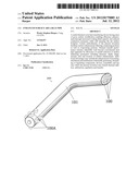
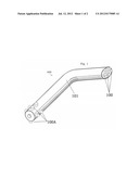
[0031] FIG. 1 is a view of the Enhanced Surface Area Heat Pipe.
[0032] FIG. 2 is a cutaway interior view of the Enhanced Surface Area Heat Pipe heat intake zone.
[0033] FIG. 3 is a typical heat pipe cutaway view of a common heat pipe heat intake zone. Not the subject of the patent application, but important to illustrate shape of the interior of a common heat pipe heat transfer zone.
[0034] FIG. 4 is a cutaway interior view of the Enhanced Surface Area Heat Pipe heat intake zone depicting the heat intake zone area.
[0035] FIG. 5 is a cutaway interior view of a common typical Heat Pipe heat intake zone depicting area of the heat intake zone area on the interior surface of the heat pipe.
[0036] FIG. 6 is a cutaway interior view of the Enhanced Surface Area Heat Pipe heat transfer zone illustrating inward dimpling of the heat transfer zone.
DRAWINGS--REFERENCE NUMERALS
[0037] 200 Enhanced Surface Area Heat Pipe [0038] 100 Enhanced Surface Area Heat Transfer Zone cutaway view [0039] 100A Enhanced Surface Area Heat Intake Zone cutaway view [0040] 100B Typical heat pipe heat intake zone cutaway view (Not subject of patent application, shown for reference.) [0041] 101 Enhanced Surface Area Heat Pipe Enclosure [0042] 102 Capillary Material [0043] 103 Working Fluid [0044] 104 Light Emitting Diode (heat generating component, not subject of patent application, shown for reference.) [0045] 105 Typical heat pipe interior cutaway view showing heat intake zone (not subject of patent application, shown for reference.)
DETAILED DESCRIPTION--FIGS. 1, 2, 3, 6--PRESENT INVENTION
[0046] For purpose toward promoting an understanding of the principles of the invention, reference will now be made to the embodiments illustrated in the drawings. Specific language will be used to describe same. It will, nevertheless, be understood that no limitation of the scope of the invention is thereby intended, such alterations and further modifications of the illustrated device, and such further applications of the principles of the invention as illustrated herein being contemplated as would normally occur to one skilled in the art to which the invention relates.
[0047] Certain terminology is used in the following description for convenience only and is not limiting. The words "right", "left", "upper", "lower", "inside", "outside", and "in front of designate the placement and location of components from the viewer's point of view. The phrase `heat transfer zone` refers to the specific area where a heat generating or dissipating component mechanically and/or thermally connects to the heat pipe enclosure. The terminology includes the words above specifically mentioned, derivatives thereof and words of similar import.
[0048] Referring now to FIG. 1 of the drawing, the Enhanced Surface Area Heat Pipe 200 is shown comprising Enclosure 101, and a plurality of Enhanced Surface Heat Transfer (exhaust) Zones 100 and Heat Transfer (Intake) Zones 100A. Enclosure 101 being fashioned of any suitable material(s), constructed by any suitable construction or assembly means, having any suitable conduction design, and having any suitable size and shape. Enhanced Surface Heat Exhaust and Intake Zones 100 and 100A formed by punch, pressure, cast, or any suitable manufacturing means into the desired areas of Enclosure 101. In order to best suit the desired application, Enhanced Surface Heat Transfer Zones (Exhaust and Intake) 100 and 100A may be formed in any suitable shape, depth and size and in an outward or inward direction in relation to Enclosure 101. Inward facing Enhanced Surface Heat Transfer Zones are illustrated in FIG. 6, 100.
[0049] Referring now to FIG. 2, Cutaway view of Enhanced Surface Area Heat Pipe Enclosure 101. Capillary Material 102 is present at the interior surface of enclosure 101. Capillary Material 102 may be fashioned of any suitable material(s), or by creating longitudinal grooving or any other effective wall treatment to enable capillary activity of Working Fluid 103, which may be of any suitable fluid(s) or compound(s) and held at any suitable pressure within the Enhanced Surface Area Heat Pipe Enclosure (FIG. 1) 200. FIG. 3 illustrates the typical internal wall shape of a typical Heat Pipe Enclosure 105 where the approximate area of the heat intake zones is depicted by the half-circular shapes on the surface above the heat generating components, Light Emitting Diodes 104.
Operation--FIGS. 1, 2, 3, 4, 5, 6
[0050] The operation of the Enhanced Surface Area Heat Pipe (FIG. 1) 200 is typical of heat pipe operation where the working fluid (FIG. 2,) 103, which resides as a liquid in capillary material (FIG. 2) 102, receives thermal energy from a heat generating component(s) (FIG. 3), 104 which is thermally connected to the heat intake zone (FIGS. 1, 2, and 4), 100A. The working fluid (FIG. 2,) 103 boils to a gas which expands to fill the Enhanced Surface Area Heat Pipe's (FIG. 1) 200 sealed interior. Cooler areas of the Enhanced Surface Area Heat Pipe (FIG. 1) 200 cause the gas to condense. The surface where condensation takes place absorbs the thermal energy and the working fluid (FIG. 2,) 103 is pulled through the capillary material (FIG. 2), 102 towards the heat intake zone (FIGS. 1-3), 100A. At the heat intake zone (FIGS. 1, 2 and 4), 100A, the capillary material (FIG. 2) 102 is in a state of lower pressure because the incoming heat continually evaporates the working fluid (FIG. 2,) 103. This `drying out` process (evaporation) continually occurs, creating the lower pressure which attracts the working fluid (FIG. 2,) 103.
[0051] The Enhanced Surface Area Heat Pipe (FIG. 1) 200 heat intake rate is improved over a typical heat pipe by engineering the structure of the Heat Intake Zone (FIGS. 1, 2, and 4), 100A. By creating an outwardly (or if better suiting a particular application, inwardly as shown in FIG. 6, 100) protruding dimple of a predetermined depth, outline, thickness and shape, the internal surface area is altered, causing increased working fluid (FIG. 2,) 103 capacity at the altered area compared to an unmodified heat intake zone (FIG. 5,) 100B with the same `footprint` or contact area. Also, the internal surface area immediately adjacent to Enhanced Surface Heat Intake Zone (FIG. 4), 100A, being removed a distance away from the center (point source of heat) of the Enhanced Surface Heat Intake Zone (FIG. 2), 100, remains cooler and allows Working Fluid (FIG. 2), 103 to remain as a fluid in a larger percentage of the area on the interior surface plane. This is because the area where the evaporation is occurring has been moved from the interior surface plane of the typical Heat Pipe Enclosure (FIGS. 3 and 5), 105 into the expanded dimpled area of the heat intake zone (FIGS. 2 and 4), 100A of the Enhanced Surface Area Heat Pipe (FIG. 1) 200. This creates higher Working Fluid (FIG. 2), 103 capacity and increases the size of the actual fluid conduction area without increasing the remaining diameter of the Enhanced Surface Area Heat Pipe Enclosure (FIG. 2), 101. Comparing the same size footprint of a typical heat intake zone (FIG. 5) 100B of a typical heat pipe enclosure (FIG. 3), 105 to the footprint of Enhanced Surface Heat Intake Zone (FIG. 4), 100A of an Enhanced Surface Area Heat Pipe (FIG. 2) 101, surface area is increased due to the creation of the vertical walls of the dimple. This increase of surface area is determined by the diameter and depth of the dimple making up the Enhanced Surface Heat Intake Zone (FIGS. 2 and 4), 100A. Note that this same dimpling principal may also be beneficial when applied to the condensing or other portions of a heat tube and may be used as shown in FIGS. 1 and 6, 100. The shape, depth and area of the Enhanced Surface Area Heat Transfer Zones (FIGS. 1,2,4 and 6), 100 and 100A can be varied to most efficiently accommodate heat transfer and shape, size and connection means of any suitable heat generating or dissipating device.
Advantages
[0052] From the description above, a number of advantages of the Enhanced Surface Area Heat Pipe become evident:
[0053] (a) Increased overall efficiency allows use of a heat pipe with less mass or smaller size, or use of a comparable sized heat pipe to transfer increased thermal energy.
[0054] (b) decreased size of dry areas (where evaporation actively takes place) on the internal surface plane increases useful working fluid capacity and increases the area available for fluid conduction without increasing the remaining size of the conduction area. Especially useful where many heat intake zones are linearly positioned along the length of the pipe causing need of liquid conduction to feed each heat intake zone and also continue past each heat intake zone.
[0055] (c) Heat Transfer zones may be sized and shaped to accommodate different heat generating/dissipating device mounting schemes.
[0056] (d) Condensing area of heat pipe can be modified using the same principals as used for the heat intake zone(s) to increase the effectiveness of the heat transfer from the heat pipe.
[0057] (e) Heat pipe may be thermally and/or physically attached from any suitable point and by any suitable means to external components and/or assemblies.
[0058] (f) Heat pipe may be designed utilizing any suitable conduction design.
[0059] Although the description above contains many specificities, these should not be construed as limiting the scope of the invention but as merely providing illustrations of some of the presently preferred embodiments.
[0060] Thus the scope of the invention should be determined by the appended claims and their legal equivalents, rather than by the examples given.
User Contributions:
Comment about this patent or add new information about this topic:
Images included with this patent application:
 |  |
| Similar patent applications: | |
| Date | Title |
|---|---|
| 2011-09-01 | Geometrically reoriented low-profile phase plane heat pipes |
| 2010-12-30 | Convection enhanced closed loop geothermal heat pump well |
| 2009-07-30 | Combined assembly of fixing base and heat pipe |
| 2010-08-26 | Assembled configuration of cooling fins and heat pipes |
| 2010-09-23 | Multilayered surrounding plate type heat dissipating structure |
| New patent applications in this class: | |
| Date | Title |
|---|---|
| 2019-05-16 | Method for preparing porous wick and product prepared by the same |
| 2019-05-16 | Semiconductor device assembly with vapor chamber |
| 2019-05-16 | Straight-through structure of heat dissipation unit |
| 2018-01-25 | Diphasic cooling loop with satellite evaporators |
| 2017-08-17 | Heat pipe |
| Top Inventors for class "Heat exchange" | |
| Rank | Inventor's name |
|---|---|
| 1 | Levi A. Campbell |
| 2 | Chun-Chi Chen |
| 3 | Tai-Her Yang |
| 4 | Robert E. Simons |
| 5 | Richard C. Chu |