Patent application title: DRIVING MODULE FOR DIGITAL VISUAL INTERFACE
Inventors:
Feng-Long He (Shenzhen, CN)
Feng-Long He (Shenzhen, CN)
Assignees:
HON HAI PRECISION INDUSTRY CO., LTD.
HONG FU JIN PRECISION INDUSTRY (ShenZhen) CO., LTD .
IPC8 Class: AG06F3038FI
USPC Class:
345211
Class name: Computer graphics processing and selective visual display systems display driving control circuitry display power source
Publication date: 2012-06-28
Patent application number: 20120162174
Abstract:
A driving module for driving a Digital Visual Interface includes an
integrated chip, a pull-up resistor unit, and a voltage converter. The
pull-up resistor unit includes a plurality of resistors. The voltage
converter includes an array of resistors comprising a plurality of
resistors and a MOSFET. Each resistor of the array of resistors includes
a first end and a second end. The first ends are electrically connected
to outputs of the integrated chip, and the second ends are electrically
connected to a drain of the MOSFET. A source of the MOSFET is connected
to ground, and a gate of the MOSFET is electrically connected to an
output of the main board.Claims:
1. A driving module for driving a Digital Visual Interface (DVI) of a
computer comprising a main board, the driving module comprising: an
integrated chip with a plurality of outputs; a pull-up resistor unit
comprising a plurality of resistors, one end of each resistor of the
pull-up resistor unit being electrically connected to one of the
plurality of outputs of the integrated chip, and the other end of each
resistor of the pull-up resistor unit being electrically connected to one
input of the DVI; a voltage converter comprising an array of resistors
comprising a plurality of resistors and a MOSFET, each resistor of the
array of resistors comprising a first end and a second end, the first
ends being electrically connected to outputs of the integrated chip, and
the second ends being electrically connected to a drain of the MOSFET, a
source of the MOSFET being connected to ground, and a gate of the MOSFET
being electrically connected to an output of the main board.
2. The driving module of claim 1, wherein the integrated chip comprises eight outputs.
3. The driving module of claim 2, wherein the array of resistors comprises eight resistors, each first end being electrically connected to one output of the integrated chip.
4. The driving module of claim 1, further comprising a plurality of filter capacitors electrically connected between the outputs of the integrated chip and the resistors of the pull-up resistor unit, respectively.
5. The driving module of claim 1, wherein a plurality of filter capacitors are electrically connected between the outputs of the integrated chip and the resistors of array of resistors, respectively.
6. The driving module of claim 1, further comprising a plurality of filter capacitors electrically connected between the outputs of the integrated chip and the resistors of array of resistors, respectively.
7. The driving module of claim 1, wherein the MOSFET is an N-type depletion mode MOSFET.
8. The driving module of claim 1, wherein the output of the main board is 3.3 volt.
Description:
BACKGROUND
[0001] 1. Technical Field
[0002] The present disclosure relates to driving modules and, more particularly to a driving module for a Digital Visual Interface (DVI).
[0003] 2. Description of Related Art
[0004] An electronic device, such as a notebook, generally includes a hardware driver electrically connected to an output of the mainframe for driving the DVI. However, the working voltage of the DVI is 3 volts, but the pull-up resistor of the DVI usually pulls the voltage output from the chip of the hardware driver from zero to 3.3 volts; so it needs an added voltage converter circuit for adjusting the voltage to the DVI.
[0005] Therefore, what is needed is a driving module to overcome the above described shortcomings
BRIEF DESCRIPTION OF THE DRAWING
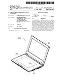
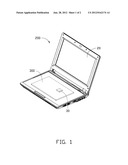
[0006] FIG. 1 is an assembled, isometric view of a notebook, in accordance with an exemplary embodiment of the present disclosure.
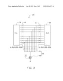
[0007] FIG. 2 is a circuit diagram of a driving module of FIG. 1.
DETAILED DESCRIPTION
[0008] Referring to FIGS. 1 to 2, an exemplary embodiment of a driving module 100 is shown. In the present embodiment, the driving module 100 is used for driving a DVI 20 of a notebook 200. The notebook 200 also includes a main board 300.
[0009] The driving module 100 includes an integrated chip 30, a pull-up resistor unit 40 electrically connected to an output of the chip 30, and a voltage converter unit 50.
[0010] In the present embodiment, the integrated chip 30 is driven by the main board 300 of the notebook 200. The chip 30 includes two groups of outputs for outputting driving signals. Each group includes three digital pins and a clock pin. A plurality of filter capacitors 60 (eight in this embodiment) each have a first end electrically connected to one corresponding output of the integrated chip 30. The filter capacitors 60 are configured for filtering direct signals output from the integrated chip 30; therefore, the integrated chip 30 only outputs alternating signals.
[0011] The pull-up resistor unit 40 includes eight resistors. Each resistor of the pull-up resistor unit 40 is electrically connected between a second end of one corresponding filter capacitor 60 and an input of the DVI 20.
[0012] The voltage converter unit 50 includes an array of resistors 51 and a MOSFET 52. In the present embodiment, the MOSFET 52 is an N-type depletion mode MOSFET. The array of resistors 51 includes eight resistors. One end of each of the eight resistors of the array of resistors 51 is electrically connected to the second end of one corresponding filter capacitors 60. The other ends of the eight resistors of the array of resistors 51 are all electrically connected to the drain of the MOSFET 52. The source of the MOSFET 52 is connected to ground. The gate of the MOSFET 52 is electrically connected to a voltage V1 output from the main board 300, which is about 3.3 volts.
[0013] At the initial of start up of the notebook 200, by supplying external power thereto, there is no voltage output from the main board 300 instantly. Therefore, the MOSFET 52 turns off because of the voltage V1 is zero, and it can prevent the array of resistors 51 from connecting to ground directly and damaging or destroying the DVI 20 at that moment. After driving the main board 300, the MOSFET 52 is in on-state. The pull-up resistor unit 40 pulls the voltage output from the integrated chip 30 to 3.3 volts, and the array of resistors 51 of the voltage converter unit 50 adjusts the voltage to 3 volts as the working voltage of the DVI 20.
[0014] It is to be further understood that even though numerous characteristics and advantages have been set forth in the foregoing description of embodiments, together with details of the structures and functions of the embodiments, the disclosure is illustrative only; and that changes may be made in detail, especially in matters of shape, size, and arrangement of parts within the principles of the disclosure to the full extent indicated by the broad general meaning of the terms in which the appended claims are expressed.
User Contributions:
Comment about this patent or add new information about this topic:
| People who visited this patent also read: | |
| Patent application number | Title |
|---|---|
| 20120208916 | Biofilm Resistant Polymer Materials |
| 20120208915 | PRINTING INK |
| 20120208914 | PHOTOINITIATOR COMPOSITIONS AND USES |
| 20120208913 | Use of Polar Additives for Enhancing Blowing Agent Solubility in Polystyrene |
| 20120208912 | FLEXIBLE POLYURETHANE FOAM AND ITS PRODUCTION PROCESS, AND SEAT CUSHION FOR AUTOMOBILE |
Images included with this patent application:
 |  |
 |
| New patent applications in this class: | |
| Date | Title |
|---|---|
| 2022-05-05 | Display substrate and display device |
| 2022-05-05 | Head mounted display device and power management method thereof |
| 2017-08-17 | Driving method of a liquid crystal display panel and liquid crystal display device |
| 2017-08-17 | Driving circuit and liquid crystal display device |
| 2017-08-17 | Data driver and a display apparatus having the same |
| New patent applications from these inventors: | |
| Date | Title |
|---|---|
| 2012-05-03 | Printed circuit board |
| 2012-03-29 | All-in-one computer audio system |
| 2011-10-13 | Timing control circuit and power supply using the same |
| 2009-06-25 | Network overclock control circuit |
| 2009-06-25 | Circuit for controlling rotation speed of computer fan |
| Top Inventors for class "Computer graphics processing and selective visual display systems" | |
| Rank | Inventor's name |
|---|---|
| 1 | Katsuhide Uchino |
| 2 | Junichi Yamashita |
| 3 | Tetsuro Yamamoto |
| 4 | Shunpei Yamazaki |
| 5 | Hajime Kimura |