Patent application title: HEAT SINK
Inventors:
Chris Lee (Sindian City, TW)
Assignees:
LEA-MIN TECHNOLOGIES CO., LTD.
IPC8 Class: AF28D1504FI
USPC Class:
16510426
Class name: Liquid fluent heat exchange material utilizing change of state utilizing capillary attraction
Publication date: 2011-09-08
Patent application number: 20110214842
Abstract:
A heat sink has a fin set and at least one heat pipe. The fin set has
multiple stacked fins and at least one tapered tube. Each fin has at
least one protrusion. The at least one protrusion protrudes from each fin
and each protrusion has an internal surface. The at least one tapered
tube is defined through corresponding protrusions of the fins. The at
least one heat pipe has at least one tapered arm and a pipe wall. The
tapered arm corresponds to and is mounted through a corresponding tapered
tube of the fin set. The pipe wall of the heat pipe abuts the internal
surfaces of corresponding protrusions of the fins tightly so heat can be
dissipated efficiently during use.Claims:
1. A heat sink comprising: a fin set comprising multiple sequentially
stacked fins, each fin having at least one protrusion protruding from the
fin and defining a tapered hole corresponding to and aligning with the
tapered hole of subsequent adjacent fins to define a tapered tube through
the fin set and having an internal surface; and at least one heat pipe
having at least one tapered arm corresponding to and mounted through a
corresponding tapered tube of the fin set and having a pipe wall abutting
corresponding internal surfaces of the protrusions of the fins.
2. The heat sink as claimed in claim 1, wherein the at least one heat pipe is U-shaped and has a central arm having two ends; and two tapered arms respectively formed on the ends of the central arm and each tapered arm formed tapered and mounted through corresponding tapered tube of the fin set.
3. The heat sink as claimed in claim 1 further having solder filled between the pipe wall of the at least one heat pipe and the internal surfaces of the protrusions.
4. The heat sink as claimed in claim 2 further having solder filled between the pipe wall of the at least one heat pipe and the internal surfaces of the protrusions.
5. The heat sink as claimed in claim 1 further having a metal seat mounted around the heat pipe.
6. The heat sink as claimed in claim 2 further having a metal seat mounted around the central arm of the heat pipe.
7. The heat sink as claimed in claim 3 further having a metal seat mounted around the heat pipe.
8. The heat sink as claimed in claim 4 further having a metal seat mounted around the central arm of the heat pipe.
Description:
BACKGROUND OF THE INVENTION
[0001] 1. Field of the Invention
[0002] The present invention relates to a heat sink, and more particularly to a heat sink that has at least one tapered heat pipe mounted through and contacting fins tightly to improve thermal conductivity.
[0003] 2. Description of the Prior Arts
[0004] A heat sink is connected to a central processing unit (CPU) to dissipate heat from the CPU so preventing the CPU from overheating and maintaining working efficiency.
[0005] A conventional heat sink is a metal device with multiple fins and at least one heat pipe. The fins are stacked and each fin has a surface area, multiple through holes and multiple protrusions. The through holes are defined through the fins and correspond to and align with the through holes of adjacent fins. The protrusions are formed around the through holes and have inner surfaces. The at least one heat pipe abuts an electronic device and is mounted through corresponding through holes and has a pipe wall. Solder is filled between the pipe wall of the at least one heat pipe and the internal surfaces of the protrusions to weld the heat pipe and the protrusions. The heat pipe absorbs heat from the electronic device and transmits the heat to the fins that radiate the heat to the air rapidly due to the surface area of the fins.
[0006] However, to ensure the heat pipe can be mounted through the fins, the through holes must be bigger than the heat pipe, in other words, there is a gap between the heat pipe and the fins. If the gap is too small, the heat pipe will be mounted through the fins not easily. If the gap is too big, the more solder must be used and thick solder will reduce thermal efficiency. Accordingly, the heat absorbed by the heat pipe is not dissipated efficiently.
[0007] To overcome the shortcomings, the present invention provides a heat sink to mitigate or obviate the aforementioned problems.
SUMMARY OF THE INVENTION
[0008] The main object of the present invention is to provide a heat sink with better heat conducting efficiency.
[0009] A heat sink comprises a fin set and at least one heat pipe. The fin set has multiple fins and multiple tapered tubes. The fins are stacked and each fin has at least one protrusion. The at least one protrusion protrudes from each fin and each protrusion has an internal surface. Each tapered tube is defined through corresponding protrusions of the fins. The at least one heat pipe has at least one tapered arm corresponding to and mounted through a corresponding tapered tube of the fin set and has a pipe wall. The pipe wall of the heat pipe abuts the internal surfaces of corresponding protrusions of the fins tightly. Therefore, the heat absorbed by the heat pipe can be dissipated efficiently during use.
[0010] Other objectives, advantages and novel features of the invention will become more apparent from the following detailed description when taken in conjunction with the accompanying drawings.
BRIEF DESCRIPTION OF THE DRAWINGS
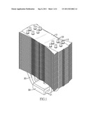
[0011] FIG. 1 is a perspective view of a heat sink in accordance with the present invention;
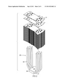
[0012] FIG. 2 is an exploded perspective view of the heat sink in FIG. 1;
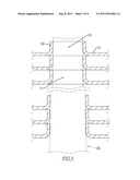
[0013] FIG. 3 is a partially enlarged side view in cross section of fins of the heat sink in FIG. 1 showing a heat pipe in phantom lines; and
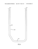
[0014] FIG. 4 is a front view of a heat pipe of the heat sink in FIG. 1.
DETAILED DESCRIPTION OF THE PREFERRED EMBODIMENTS
[0015] With reference to FIGS. 1 and 2, a heat sink in accordance with the present invention comprises a fin set, at least one heat pipe (20) and a metal seat (30).
[0016] With further reference to FIG. 3, the fin set has multiple fins (10) and at least one tapered tube (11). The fins (10) are stacked in sequence and each fin (10) has at least one protrusion (12). The at least one protrusion (12) protrudes from each fin (10), has an internal surface and a tapered hole (13). The tapered hole (13) is defined through the protrusion (12) of each fin (10) and corresponds to and aligns with the tapered hole (13) of subsequent adjacent fins (10). Each tapered tube (11) is formed through the fin set and is defined in corresponding tapered holes (13) of the fins (10), each tapered tube (11) has a bottom hole edge and a top hole edge.
[0017] With further reference to FIG. 4, the at least one heat pipe (20) has at least one tapered arm corresponding to and mounted through a corresponding tapered tube (13) of the fin set and has a pipe wall. The pipe wall of the heat pipe (20) abuts corresponding internal surfaces of the protrusions (12) tightly. Solder may be filled between the pipe wall of the at least one heat pipe (20) and the internal surfaces of the protrusions (12) to weld the heat pipe (20) and the protrusions (12) more securely. In a preferred embodiment, the at least one heat pipe (20) is U-shaped and has a central arm (21) and two tapered arms (22). The central arm (21) has two ends. The tapered arms (22) are respectively formed on the ends of the central arm (21) and each tapered arm (22) is tapered and is mounted through corresponding tapered tubes (11) of the fin set.
[0018] The metal seat (30) is mounted around the heat pipe (20) and abuts an electronic device, such as, a CPU. Heat generated by the CPU can be transmitted to the heat pipe (20) via the metal seat (30). In a preferred embodiment, the metal seat (30) is mounted around the central arm (21) of the heat pipe (20).
[0019] Since the tapered tubes (11) of the fin set are tapered and correspond to the heat pipe (20), which also is tapered, the heat pipe (20) is mounted through the tapered tubes (11) of the fin set smoothly and the pipe wall of the heat pipe (20) abuts the internal surface of the protrusions (12) of the fins (10) tightly. Therefore, heat absorbed by the heat pipe (20) can be transmitted to the fins (10) to be dissipated efficiently and thermal conductivity of the heat sink as described is improved.
[0020] Even though numerous characteristics and advantages of the present invention have been set forth in the foregoing description, together with details of the structure and features of the invention, the disclosure is illustrative only. Changes may be made in the details, especially in matters of shape, size, and arrangement of parts within the principles of the invention to the full extent indicated by the broad general meaning of the terms in which the appended claims are expressed.
User Contributions:
Comment about this patent or add new information about this topic:
| People who visited this patent also read: | |
| Patent application number | Title |
|---|---|
| 20170362179 | Quinolines, Polyquinolines, Molecular Segments of Fullerenes and Graphene Nanoribbons, and Graphene Nanoribbons and Methods of Their Synthesis |
| 20170362178 | PROCESS FOR PREPARING [(3-HYDROXYPYRIDINE-2-CARBONYL)AMINO]ALKANOIC ACIDS, ESTERS AND AMIDES |
| 20170362177 | METHODS OF MANUFACTURING CERTAIN SUBSTITUTED SULFILIMINES |
| 20170362175 | NOVEL FORMS OF APREMILAST |
| 20170362174 | A NOVEL PROCESS FOR THE PREPARATION OF CONSIDERABLY PURE SILODOSIN |
Images included with this patent application:
 |  |
 |  |
| New patent applications in this class: | |
| Date | Title |
|---|---|
| 2019-05-16 | Method for preparing porous wick and product prepared by the same |
| 2019-05-16 | Semiconductor device assembly with vapor chamber |
| 2019-05-16 | Straight-through structure of heat dissipation unit |
| 2018-01-25 | Diphasic cooling loop with satellite evaporators |
| 2017-08-17 | Heat pipe |
| Top Inventors for class "Heat exchange" | |
| Rank | Inventor's name |
|---|---|
| 1 | Levi A. Campbell |
| 2 | Chun-Chi Chen |
| 3 | Tai-Her Yang |
| 4 | Robert E. Simons |
| 5 | Richard C. Chu |