Patent application title: IMPLANTABLE BIO-MEDICAL UNIT WITH ELECTRO-MECHANICAL FUNCTION
Inventors:
Ahmadreza (reza) Rofougaran (Newport Coast, CA, US)
Assignees:
BROADCOM CORPORATION
IPC8 Class: AA61M514FI
USPC Class:
6048911
Class name: Surgery controlled release therapeutic device or system implanted dynamic device or system
Publication date: 2011-03-31
Patent application number: 20110077623
es a power harvesting module, a communication
module, a processing module, and a micro electro-mechanical functional
module. The power harvesting module converts a power source signal into a
supply voltage that powers the other modules. The communication module
converts inbound wireless communication signal into an inbound symbol
stream and converts an outbound symbol stream into an outbound wireless
communication signal. The processing module converts the inbound symbol
stream into inbound data; generates a command message based on the
inbound data; and converts an electro-mechanical response into the
outbound symbol stream. The micro electro-mechanical functional module
performs an electro-mechanical function within a hosting body in
accordance with the command message and, when requested per the command
message, generates the electro-mechanical response based on the
performing the electro-mechanical function.Claims:
1. A bio-medical unit comprises:a power harvesting module operable
to:receive a power source signal; andconvert the power source signal into
a supply voltage;a communication module powered by the supply voltage,
wherein the communication module is operable to:receive an inbound
wireless communication signal;convert the inbound wireless communication
signal into an inbound symbol stream;convert an outbound symbol stream
into an outbound wireless communication signal; andtransmit the outbound
wireless communication signal;a processing module powered by the supply
voltage, wherein the processing module is operable to:convert the inbound
symbol stream into inbound data;generate a command message based on the
inbound data; andconvert an electro-mechanical response into the outbound
symbol stream; anda micro electro-mechanical functional module powered by
the supply voltage, wherein the micro electro-mechanical functional
module is operable to:receive the command message;perform an
electro-mechanical function within a hosting body in accordance with the
command message; andwhen requested per the command message, generate the
electro-mechanical response based on the performing the
electro-mechanical function.
2. The bio-medical unit of claim 1, wherein the power source signal comprises at least one of:an electromagnetic signal;a radio frequency signal;a millimeter wave signal;an ultrasound signal; anda light signal.
3. The bio-medical unit of claim 1, wherein each of the inbound and outbound wireless communication signals comprises at least one of:a radio frequency communication signal;a millimeter wave communication signal; andan electromagnetic communication signal.
4. The bio-medical unit of claim 1, electro-mechanical function module comprises at least one of:a motion propulsion module;a transducer module;a flow meter module;a gyroscope module;an accelerometer module;an electrostatic motor module; andan actuator module.
5. The bio-medical unit of claim 1 further comprises:the processing module is further operable to generate a capture digital image command as the command message;the micro electro-mechanical functional module is further operable to:receive the capture digital image command;capture a digital image as the electro-mechanical function in response to the digital image command; andsend the digital image to the processing module; andthe processing module is further operable to convert the digital image into the outbound symbol stream.
6. The bio-medical unit of claim 1 further comprises:the processing module is further operable to generate a collect a biological sample command as the command message;the micro electro-mechanical functional module is further operable to:receive the collect the biological sample command;collect a sample of biological material as the electro-mechanical function in response to the collect the biological sample command to produce a collected sample;analyze the collected sample to produce a sample analysis; andsend the sample analysis to the processing module; andthe processing module is further operable to convert the sample analysis into the outbound symbol stream.
7. The bio-medical unit of claim 1 further comprises:the processing module is further operable to generate an administer treatment command as the command message; andthe micro electro-mechanical functional module is further operable to:receive the administer treatment command;administer a treatment as the electro-mechanical function in response to the administer treatment command, wherein the treatment is one of applying laser treatment, applying ultrasound treatment, grasping, sawing, drilling, and providing an electronic stimulus.
8. The bio-medical unit of claim 1 further comprises:the processing module is further operable to generate a release medication command as the command message; andthe micro electro-mechanical functional module is further operable to:receive the release medication command;release an amount of medication as the electro-mechanical function in accordance with the release medication command.
9. The bio-medical unit of claim 1 further comprises:the processing module is further operable to generate a produce high voltage stimuli command as the command message; andthe micro electro-mechanical functional module is further operable to:receive the high voltage stimuli command;in response to the high voltage stimuli command:establish a common ground with another bio-medical unit; andproduce a high voltage in accordance with the high voltage stimuli command.
10. The bio-medical unit of claim 1, wherein the micro electro-mechanical function module comprises:a canister module for storing a fluid;a fluid route control module coupled to the canister module;an external contact module coupled to the fluid route control module, wherein the fluid route control module controls flow of fluid between the canister module and the external contact module.
11. The bio-medical unit of claim 10 further comprises:the fluid route control module including at least one of a value module and a pump module; andthe external contact module including at least one of a needle module and a delivery tube.
12. The bio-medical unit of claim 1, wherein the micro electro-mechanical function module comprises:a first receptacle module to receive a first medication ingredient from a first other bio-medical unit;a second receptacle module to receive a second medication ingredient from a second other bio-medical unit; anda mixing and release module operable to:mix the first and second medication ingredients to produce a mixed medication; andrelease the mixed medication in accordance with the command message.
13. A bio-medical unit comprises:a power harvesting module operable to:receive a power source signal; andconvert the power source signal into a supply voltage;a communication module powered by the supply voltage, wherein the communication module is operable to:receive an inbound wireless communication signal;convert the inbound wireless communication signal into an inbound symbol stream;convert an outbound symbol stream into an outbound wireless communication signal; andtransmit the outbound wireless communication signal;a processing module powered by the supply voltage, wherein the processing module is operable to:convert the inbound symbol stream into inbound data;generate a command message based on the inbound data; andconvert an electro-mechanical response into the outbound symbol stream; anda canister module for storing a medication ingredient; anda release module mechanically coupled to the canister module, wherein the release module is operable to:receive the command message;retrieve a specified amount of the medication ingredient from the canister module in accordance with the command message; andrelease the medication ingredient into a hosting body in accordance with the command message.
14. The bio-medical unit of claim 13 further comprises:a second canister module for storing a second medication ingredient, wherein the release module is further operable to:retrieve a specified amount of the second medication ingredient from the second canister module in accordance with the command message;mix the medication ingredient with the second medication ingredient to produce a mixed medication; andrelease the mixed medication into the hosting body in accordance with the command message.
15. The bio-medical unit of claim 13, wherein the canister module further comprises:a refill mechanism to receive the medication ingredient from another bio-medical unit or for a source external to the hosting body.
16. A network of bio-medical units comprises:a first bio-medical unit that includes:a first power harvesting module to generate a first supply voltage from an external power source signal;a first communication module that is powered by the first supply voltage and supports in-body wireless communications and out-of-body wireless communications; anda first functional module that is powered by the first supply voltage and performs a first function; anda second bio-medical unit that includes:a second power harvesting module to generate a second supply voltage from the external power source signal;a second communication module that is powered by the second supply voltage and supports the in-body wireless communications and the out-of-body wireless communications; anda second functional module that is powered by the second supply voltage and performs a second function in concert with the first function within a hosting body.
17. The network of bio-medical units of claim 16 further comprises:the first function including generating a first voltage; andthe second function including generating a second voltage, wherein the first and second voltages provide an electrical stimulation within the hosting body.
18. The network of bio-medical units of claim 16 further comprises:a third bio-medical unit that includes:a third power harvesting module to generate a third supply voltage from the external power source signal;a third communication module that is powered by the third supply voltage and supports the in-body wireless communications and the out-of-body wireless communications; anda processing module operable to generate a command that is transmitted as one of the in-body wireless communications, wherein the command coordinates performance of at least one of the first and second functions.
19. The network of bio-medical units of claim 16 further comprises:the first function including transferring a medication ingredient; andthe second function including receiving the medication ingredient.Description:
CROSS REFERENCE TO RELATED PATENTS
[0001]This patent application is claiming priority under 35 USC §119 to a provisionally filed patent application entitled BIO-MEDICAL UNIT AND APPLICATIONS THEREOF, having a provisional filing date of Sep. 30, 2009, and a provisional Ser. No. 61/247,060.
STATEMENT REGARDING FEDERALLY SPONSORED RESEARCH OR DEVELOPMENT
[0002]NOT APPLICABLE
INCORPORATION-BY-REFERENCE OF MATERIAL SUBMITTED ON A COMPACT DISC
[0003]NOT APPLICABLE
BACKGROUND OF THE INVENTION
[0004]1. Technical Field of the Invention
[0005]This invention relates generally to medical equipment and more particularly to wireless medical equipment.
[0006]2. Description of Related Art
[0007]As is known, there is a wide variety of medical equipment that aids in the diagnosis, monitoring, and/or treatment of patients' medical conditions. For instances, there are diagnostic medical devices, therapeutic medical devices, life support medical devices, medical monitoring devices, medical laboratory equipment, etc. As specific exampled magnetic resonance imaging (MRI) devices produce images that illustrate the internal structure and function of a body.
[0008]The advancement of medical equipment is in step with the advancements of other technologies (e.g., radio frequency identification (RFID), robotics, etc.). Recently, RFID technology has been used for in vitro use to store patient information for easy access. While such in vitro applications have begun, the technical advancement in this area is in its infancy.
BRIEF SUMMARY OF THE INVENTION
[0009]The present invention is directed to apparatus and methods of operation that are further described in the following Brief Description of the Drawings, the Detailed Description of the Invention, and the claims. Other features and advantages of the present invention will become apparent from the following detailed description of the invention made with reference to the accompanying drawings.
BRIEF DESCRIPTION OF THE SEVERAL VIEWS OF THE DRAWING(S)
[0010]FIG. 1 is a diagram of an embodiment of a system in accordance with the present invention;
[0011]FIG. 2 is a diagram of another embodiment of a system in accordance with the present invention;
[0012]FIG. 3 is a diagram of an embodiment of an artificial body part including one or more bio-medical units in accordance with the present invention;
[0013]FIG. 4 is a schematic block diagram of an embodiment of an artificial body part in accordance with the present invention;
[0014]FIG. 5 is a diagram of another embodiment of a system in accordance with the present invention;
[0015]FIG. 6 is a diagram of another embodiment of a system in accordance with the present invention;
[0016]FIG. 7 is a diagram of another embodiment of a system in accordance with the present invention;
[0017]FIG. 8 is a schematic block diagram of an embodiment of a bio-medical unit in accordance with the present invention;
[0018]FIG. 9 is a schematic block diagram of an embodiment of a power harvesting module in accordance with the present invention;
[0019]FIG. 10 is a schematic block diagram of another embodiment of a power harvesting module in accordance with the present invention;
[0020]FIG. 11 is a schematic block diagram of another embodiment of a power harvesting module in accordance with the present invention;
[0021]FIG. 12 is a schematic block diagram of another embodiment of a power harvesting module in accordance with the present invention;
[0022]FIG. 13 is a schematic block diagram of another embodiment of a bio-medical unit in accordance with the present invention;
[0023]FIG. 14 is a diagram of another embodiment of a system in accordance with the present invention;
[0024]FIG. 15 is a diagram of an example of a communication protocol within a system in accordance with the present invention;
[0025]FIG. 16 is a diagram of another embodiment of a system in accordance with the present invention;
[0026]FIG. 17 is a diagram of another example of a communication protocol within a system in accordance with the present invention;
[0027]FIG. 18 is a diagram of an embodiment of a network of bio-medical units that include MEMS robotics in accordance with the present invention;
[0028]FIG. 19 is a diagram of another embodiment of a network of bio-medical units that include MEMS robotics in accordance with the present invention;
[0029]FIG. 20 is a diagram of an embodiment of a bio-medical unit collecting image data in accordance with the present invention;
[0030]FIG. 21 is a diagram of another embodiment of a network of bio-medical units communicating via light signaling in accordance with the present invention;
[0031]FIG. 22 is a diagram of an embodiment of a bio-medical unit collecting audio and/or ultrasound data in accordance with the present invention;
[0032]FIG. 23 is a diagram of another embodiment of a network of bio-medical units communicating via audio and/or ultrasound signaling in accordance with the present invention;
[0033]FIG. 24 is a diagram of an embodiment of a network of bio-medical units collecting ultrasound data in accordance with the present invention;
[0034]FIG. 25 is a diagram of an embodiment of a network of bio-medical units for facilitating electrical stimulus treatment in accordance with the present invention;
[0035]FIG. 26 is a diagram of an embodiment of power conversion modules in a bio-medical unit of FIG. 25 in accordance with the present invention;
[0036]FIG. 27 is a schematic block diagram of another embodiment of a bio-medical unit in accordance with the present invention;
[0037]FIG. 28 is a schematic block diagram of another embodiment of a bio-medical unit in accordance with the present invention;
[0038]FIG. 29 is a schematic block diagram of another embodiment of a bio-medical unit in accordance with the present invention;
[0039]FIG. 30 is a schematic block diagram of another embodiment of a bio-medical unit in accordance with the present invention;
[0040]FIG. 31 is a schematic block diagram of another embodiment of a bio-medical unit in accordance with the present invention;
[0041]FIG. 32 is a schematic block diagram of another embodiment of a bio-medical unit in accordance with the present invention;
[0042]FIG. 33 is a diagram of an embodiment of a bio-medical unit including a controlled release module in accordance with the present invention;
[0043]FIG. 34 is a diagram of an embodiment of a controlled release module in accordance with the present invention;
[0044]FIG. 35 is a diagram of an embodiment of a system of bio-medical units for controlled release of a medication in accordance with the present invention; and
[0045]FIG. 36 is a diagram of an embodiment of a bio-medical unit including sampling modules in accordance with the present invention.
DETAILED DESCRIPTION OF THE INVENTION
[0046]FIG. 1 is a diagram of an embodiment of a system that includes a plurality of bio-medical units 10 embedded within a body and/or placed on the surface of the body to facilitate diagnosis, treatment, and/or data collections. Each of the bio-medical units 10 is a passive device (e.g., it does not include a power source (e.g., a battery)) and, as such, includes a power harvesting module. The bio-medical units 10 may also include one or more of memory, a processing module, and functional modules. Alternatively, or in addition to, each of the bio-medical units 10 may include a rechargeable power source.
[0047]In operation, a transmitter 12 emits electromagnetic signals 16 that pass through the body and are received by a receiver 14. The transmitter 12 and receiver 14 may be part of a piece of medical diagnostic equipment (e.g., magnetic resonance imaging (MRI), X-ray, etc.) or independent components for stimulating and communicating with the network of bio-medical units in and/or on a body. One or more of the bio-medical units 10 receives the transmitted electromagnetic signals 16 and generates a supply voltage therefrom. Examples of this will be described in greater detail with reference to FIGS. 8-12.
[0048]Embedded within the electromagnetic signals 16 (e.g., radio frequency (RF) signals, millimeter wave (MMW) signals, MRI signals, etc.) or via separate signals, the transmitter 12 communicates with one or more of the bio-medical units 10. For example, the electromagnetic signals 16 may have a frequency in the range of a few MHz to 900 MHz and the communication with the bio-medical units 10 is modulated on the electromagnetic signals 16 at a much higher frequency (e.g., 5 GHz to 300 GHz). As another example, the communication with the bio-medical units 10 may occur during gaps (e.g., per protocol of medical equipment or injected for communication) of transmitting the electromagnetic signals 16. As another example, the communication with the bio-medical units 10 occurs in a different frequency band and/or using a different transmission medium (e.g., use RF or MMW signals when the magnetic field of the electromagnetic signals are dominate, use ultrasound signals when the electromagnetic signals 16 are RF and/or MMW signals, etc.).
[0049]One or more of the bio-medical units 10 receives the communication signals 18 and processes them accordingly. The communication signals 18 may be instructions to collect data, to transmit collected data, to move the unit's position in the body, to perform a function, to administer a treatment, etc. If the received communication signals 18 require a response, the bio-medical unit 10 prepares an appropriate response and transmits it to the receiver 14 using a similar communication convention used by the transmitter 12.
[0050]FIG. 2 is a diagram of another embodiment of a system that includes a plurality of bio-medical units 10 embedded within a body and/or placed on the surface of the body to facilitate diagnosis, treatment, and/or data collections. Each of the bio-medical units 10 is a passive device and, as such, includes a power harvesting module. The bio-medical units 10 may also include one or more of memory, a processing module, and functional modules. In this embodiment, the person is placed in an MRI machine (fixed or portable) that generates a magnetic field 26 through which the MRI transmitter 20 transmits MRI signals 28 to the MRI receiver 22.
[0051]One or more of the bio-medical units 10 powers itself by harvesting energy from the magnetic field 26 or changes thereof as produced by gradient coils, from the magnetic fields of the MRI signals 28, from the electrical fields of the MRI signals 28, and/or from the electromagnetic aspects of the MRI signals 28. A unit 10 converts the harvested energy into a supply voltage that supplies other components of the unit (e.g., a communication module, a processing module, memory, a functional module, etc.).
[0052]A communication device 24 communicates data and/or control communications 30 with one or more of the bio-medical units 10 over one or more wireless links. The communication device 24 may be a separate device from the MRI machine or integrated into the MRI machine. For example, the communication device 24, whether integrated or separate, may be a cellular telephone, a computer with a wireless interface (e.g., a WLAN station and/or access point, Bluetooth, a proprietary protocol, etc.), etc. A wireless link may be one or more frequencies in the ISM band, in the 60 GHz frequency band, the ultrasound frequency band, and/or other frequency bands that supports one or more communication protocols (e.g., data modulation schemes, beamforming, RF or MMW modulation, encoding, error correction, etc.).
[0053]The composition of the bio-medical units 10 includes non-ferromagnetic materials (e.g., paramagnetic or diamagnetic) and/or metal alloys that are minimally affected by an external magnetic field 26. In this regard, the units harvest power from the MRI signals 28 and communicate using RF and/or MMW electromagnetic signals with negligible chance of encountering the projectile or missile effect of implants that include ferromagnetic materials.
[0054]FIG. 3 is a diagram of an embodiment of an artificial body part 32 including one or more bio-medical units 10 that may be surgically implanted into a body. The artificial body part 32 may be a pace maker, a breast implant, a joint replacement, an artificial bone, splints, fastener devices (e.g., screws, plates, pins, sutures, etc.), artificial organ, etc. The artificial body part 32 may be permanently embedded in the body or temporarily embedded into the body.
[0055]FIG. 4 is a schematic block diagram of an embodiment of an artificial body part 32 that includes one or more bio-medical units 10. For instance, one bio-medical unit 10 may be used to detect infections, the body's acceptance of the artificial body part 32, measure localized body temperature, monitor performance of the artificial body part 32, and/or data gathering for other diagnostics. Another bio-medical unit 10 may be used for deployment of treatment (e.g., disperse medication, apply electrical stimulus, apply RF radiation, apply laser stimulus, etc.). Yet another bio-medical unit 10 may be used to adjust the position of the artificial body part 32 and/or a setting of the artificial body part 32. For example, a bio-medical unit 10 may be used to mechanically adjust the tension of a splint, screws, etc. As another example, a bio-medical unit 10 may be used to adjust an electrical setting of the artificial body part 32.
[0056]FIG. 5 is a diagram of another embodiment of a system that includes a plurality of bio-medical units 10 and one or more communication devices 24 coupled to a wide area network (WAN) communication device 34 (e.g., a cable modem, DSL modem, base station, access point, hot spot, etc.). The WAN communication device 34 is coupled to a network 42 (e.g., cellular telephone network, internet, etc.), which has coupled to it a plurality of remote monitors 36, a plurality of databases 40, and a plurality of computers 38.
[0057]In an example of operation, one or more of the remote monitors 36 may receive images and/or other data 30 from one or more of the bio-medical units 10 via the communication device 24, the WAN communication device 34, and the network 42. In this manner, a person(s) operating the remote monitors 36 may view images and/or the data 30 gathered by the bio-medical units 10. This enables a specialist to be consulted without requiring the patient to travel to the specialist's office.
[0058]In another example of operation, one or more of the computers 38 may communicate with the bio-medical units 10 via the communication device 24, the WAN communication device 34, and the network 42. In this example, the computer 36 may provide commands 30 to one or more of the bio-medical units 10 to gather data, to dispense a medication, to move to a new position in the body, to perform a mechanical function (e.g., cut, grasp, drill, puncture, stitch, patch, etc.), etc. As such, the bio-medical units 10 may be remotely controlled via one or more of the computers 36.
[0059]In another example of operation, one or more of the bio-medical units 10 may read and/or write data from or to one or more of the databases 40. For example, data (e.g., a blood sample analysis) generated by one or more of the bio-medical units 10 may be written to one of the databases 40. The communication device 24 and/or one of the computers 36 may control the writing of data to or the reading of data from the database(s) 40. The data may further include medical records, medical images, prescriptions, etc.
[0060]FIG. 6 is a diagram of another embodiment of a system that includes a plurality of bio-medical units 10. In this embodiment, the bio-medical units 10 can communicate with each other directly and/or communicate with the communication device 24 directly. The communication medium may be an infrared channel(s), an RF channel(s), a MMW channel(s), and/or ultrasound. The units may use a communication protocol such as token passing, carrier sense, time division multiplexing, code division multiplexing, frequency division multiplexing, etc.
[0061]FIG. 7 is a diagram of another embodiment of a system that includes a plurality of bio-medical units 10. In this embodiment, one of the bio-medical units 44 functions as an access point for the other units. As such, the designated unit 44 routes communications between the units 10 and between one or more units 10 and the communication device 24. The communication medium may be an infrared channel(s), an RF channel(s), a MMW channel(s), and/or ultrasound. The units 10 may use a communication protocol such as token passing, carrier sense, time division multiplexing, code division multiplexing, frequency division multiplexing, etc.
[0062]FIG. 8 is a schematic block diagram of an embodiment of a bio-medical unit 10 that includes a power harvesting module 46, a communication module 48, a processing module 50, memory 52, and one or more functional modules 54. The processing module 50 may be a single processing device or a plurality of processing devices. Such a processing device may be a microprocessor, micro-controller, digital signal processor, microcomputer, central processing unit, field programmable gate array, programmable logic device, state machine, logic circuitry, analog circuitry, digital circuitry, and/or any device that manipulates signals (analog and/or digital) based on hard coding of the circuitry and/or operational instructions. The processing module 50 may have an associated memory 52 and/or memory element, which may be a single memory device, a plurality of memory devices, and/or embedded circuitry of the processing module. Such a memory device 52 may be a read-only memory, random access memory, volatile memory, non-volatile memory, static memory, dynamic memory, flash memory, cache memory, and/or any device that stores digital information. Note that if the processing module 50 includes more than one processing device, the processing devices may be centrally located (e.g., directly coupled together via a wired and/or wireless bus structure) or may be distributedly located (e.g., cloud computing via indirect coupling via a local area network and/or a wide area network). Further note that when the processing module 50 implements one or more of its functions via a state machine, analog circuitry, digital circuitry, and/or logic circuitry, the memory and/or memory element storing the corresponding operational instructions may be embedded within, or external to, the circuitry comprising the state machine, analog circuitry, digital circuitry, and/or logic circuitry. Still further note that, the memory element stores, and the processing module executes, hard coded and/or operational instructions corresponding to at least some of the steps and/or functions illustrated in FIGS. 1-36.
[0063]The power harvesting module 46 may generate one or more supply voltages 56 (Vdd) from a power source signal (e.g., one or more of MRI electromagnetic signals 16, magnetic fields 26, RF signals, MMW signals, ultrasound signals, light signals, and body motion). The power harvesting module 46 may be implemented as disclosed in U.S. Pat. No. 7,595,732 to generate one or more supply voltages from an RF signal. The power harvesting module 46 may be implemented as shown in one or more FIGS. 9-11 to generate one or more supply voltages 56 from an MRI signal 28 and/or magnetic field 26. The power harvesting module 46 may be implemented as shown in FIG. 12 to generate one or more supply voltage 56 from body motion. Regardless of how the power harvesting module generates the supply voltage(s), the supply voltage(s) are used to power the communication module 48, the processing module 50, the memory 52, and/or the functional modules 54.
[0064]In an example of operation, a receiver section of the communication module 48 receives an inbound wireless communication signal 60 and converts it into an inbound symbol stream. For example, the receiver section amplifies an inbound wireless (e.g., RF or MMW) signal 60 to produce an amplified inbound RF or MMW signal. The receiver section may then mix in-phase (I) and quadrature (Q) components of the amplified inbound RF or MMW signal with in-phase and quadrature components of a local oscillation to produce a mixed I signal and a mixed Q signal. The mixed I and Q signals are combined to produce an inbound symbol stream. In this embodiment, the inbound symbol may include phase information (e.g., +/-Δθ [phase shift] and/or θ(t) [phase modulation]) and/or frequency information (e.g., +/-Δf [frequency shift] and/or f(t) [frequency modulation]). In another embodiment and/or in furtherance of the preceding embodiment, the inbound RF or MMW signal includes amplitude information (e.g., +/-ΔA [amplitude shift] and/or A(t) [amplitude modulation]). To recover the amplitude information, the receiver section includes an amplitude detector such as an envelope detector, a low pass filter, etc.
[0065]The processing module 50 converts the inbound symbol stream into inbound data and generates a command message based on the inbound data. The command message may instruction one or more of the functional modules to perform one or more electro-mechanical functions of gathering data, dispensing a medication, moving to a new position in the body, performing a mechanical function (e.g., cut, grasp, drill, puncture, stitch, patch, etc.), dispensing a treatment, collecting a biological sample, etc.
[0066]To convert the inbound symbol stream into the inbound data (e.g., voice, text, audio, video, graphics, etc.), the processing module 50 may perform one or more of: digital intermediate frequency to baseband conversion, time to frequency domain conversion, space-time-block decoding, space-frequency-block decoding, demodulation, frequency spread decoding, frequency hopping decoding, beamforming decoding, constellation demapping, deinterleaving, decoding, depuncturing, and/or descrambling. Such a conversion is typically prescribed by one or more wireless communication standards (e.g., GSM, CDMA, WCDMA, HSUPA, HSDPA, WiMAX, EDGE, GPRS, IEEE 802.11, Bluetooth, ZigBee, universal mobile telecommunications system (UMTS), long term evolution (LTE), IEEE 802.16, evolution data optimized (EV-DO), etc.).
[0067]The processing module 50 provides the command message to one or more of the micro-electromechanical functional modules 54. The functional module 54 performs an electro-mechanical function within a hosting body in accordance with the command message. Such an electro-mechanical function includes at least one of data gathering, motion, repairs, dispensing medication, biological sampling, diagnostics, applying laser treatment, applying ultrasound treatment, grasping, sawing, drilling, providing an electronic stimulus etc. Note that the functional modules 54 may be implemented using nanotechnology and/or microelectronic mechanical systems (MEMS) technology. Further note that various examples of functional modules 54 are illustrated in one or more of FIGS. 13-36.
[0068]When requested per the command message (e.g. gather data and report the data), the micro electro-mechanical functional module 54 generates an electro-mechanical response based on the performing the electro-mechanical function. For example, the response may be data (e.g., heart rate, blood sugar levels, temperature, etc.), a biological sample (e.g., blood sample, tissue sample, etc.), acknowledgement of performing the function (e.g., acknowledge a software update, storing of data, etc.), and/or any appropriate response. The micro electro-mechanical functional module 54 provides the response to the processing module 50.
[0069]The processing module 50 converts the electro-mechanical response into an outbound symbol stream, which may be done in accordance with one or more wireless communication standards (e.g., GSM, CDMA, WCDMA, HSUPA, HSDPA, WiMAX, EDGE, GPRS, IEEE 802.11, Bluetooth, ZigBee, universal mobile telecommunications system (UMTS), long term evolution (LTE), IEEE 802.16, evolution data optimized (EV-DO), etc.). Such a conversion includes one or more of: scrambling, puncturing, encoding, interleaving, constellation mapping, modulation, frequency spreading, frequency hopping, beamforming, space-time-block encoding, space-frequency-block encoding, frequency to time domain conversion, and/or digital baseband to intermediate frequency conversion.
[0070]A transmitter section of the communication module 48 converts an outbound symbol stream into an outbound RF or MMW signal 60 that has a carrier frequency within a given frequency band (e.g., 900 MHz, 2.5 GHz, 5 GHz, 57-66 GHz, etc.). In an embodiment, this may be done by mixing the outbound symbol stream with a local oscillation to produce an up-converted signal. One or more power amplifiers and/or power amplifier drivers amplifies the up-converted signal, which may be RF or MMW bandpass filtered, to produce the outbound RF or MMW signal 60. In another embodiment, the transmitter section includes an oscillator that produces an oscillation. The outbound symbol stream provides phase information (e.g., +/-Aθ [phase shift] and/or θ(t) [phase modulation]) that adjusts the phase of the oscillation to produce a phase adjusted RF or MMW signal, which is transmitted as the outbound RF signal 60. In another embodiment, the outbound symbol stream includes amplitude information (e.g., A(t) [amplitude modulation]), which is used to adjust the amplitude of the phase adjusted RF or MMW signal to produce the outbound RF or MMW signal 60.
[0071]In yet another embodiment, the transmitter section includes an oscillator that produces an oscillation. The outbound symbol provides frequency information (e.g., +/-Δf [frequency shift] and/or f(t) [frequency modulation]) that adjusts the frequency of the oscillation to produce a frequency adjusted RF or MMW signal, which is transmitted as the outbound RF or MMW signal 60. In another embodiment, the outbound symbol stream includes amplitude information, which is used to adjust the amplitude of the frequency adjusted RF or MMW signal to produce the outbound RF or MMW signal 60. In a further embodiment, the transmitter section includes an oscillator that produces an oscillation. The outbound symbol provides amplitude information (e.g., +/-ΔA [amplitude shift] and/or A(t) [amplitude modulation) that adjusts the amplitude of the oscillation to produce the outbound RF or MMW signal 60.
[0072]Note that the bio-medical unit 10 may be encapsulated by an encapsulate 58 that is non-toxic to the body. For example, the encapsulate 58 may be a silicon based product, a non-ferromagnetic metal alloy (e.g., stainless steel), etc. As another example, the encapsulate 58 may include a spherical shape and have a ferromagnetic liner that shields the unit from a magnetic field and to offset the forces of the magnetic field. Further note that the bio-medical unit 10 may be implemented on a single die that has an area of a few millimeters or less. The die may be fabricated in accordance with CMOS technology, Gallium-Arsenide technology, and/or any other integrated circuit die fabrication process.
[0073]FIG. 9 is a schematic block diagram of an embodiment of a power harvesting module 46 that includes an array of on-chip air core inductors 64, a rectifying circuit 66, capacitors, and a regulation circuit 68. The inductors 64 may each having an inductance of a few nano-Henries to a few micro-Henries and may be coupled in series, in parallel, or a series parallel combination.
[0074]In an example of operation, the MRI transmitter 20 transmits MRI signals 28 at a frequency of 3-45 MHz at a power level of up to 35 KWatts. The air core inductors 64 are electromagnetically coupled to generate a voltage from the magnetic and/or electric field generated by the MRI signals 28. Alternatively or in addition to, the air core inductors 64 may generate a voltage from the magnetic field 26 and changes thereof produced by the gradient coils. The rectifying circuit 66 rectifies the AC voltage produced by the inductors to produce a first DC voltage. The regulation circuit generates one or more desired supply voltages 56 from the first DC voltage.
[0075]The inductors 64 may be implemented on one more metal layers of the die and include one or more turns per layer. Note that trace thickness, trace length, and other physical properties affect the resulting inductance.
[0076]FIG. 10 is a schematic block diagram of another embodiment of a power harvesting module 46 that includes a plurality of on-chip air core inductors 70, a plurality of switching units (S), a rectifying circuit 66, a capacitor, and a switch controller 72. The inductors 70 may each having an inductance of a few nano-Henries to a few micro-Henries and may be coupled in series, in parallel, or a series parallel combination.
[0077]In an example of operation, the MRI transmitter 20 transmits MRI signals 28 at a frequency of 3-45 MHz at a power level of up to 35 KWatts. The air core inductors 70 are electromagnetically coupled to generate a voltage from the magnetic and/or electric field generated by the MRI signals 28. The switching module 72 engages the switches via control signals 74 to couple the inductors 70 in series and/or parallel to generate a desired AC voltage. The rectifier circuit 66 and the capacitor(s) convert the desired AC voltage into the one or more supply voltages 56.
[0078]FIG. 11 is a schematic block diagram of another embodiment of a power harvesting module 46 that includes a plurality of Hall effect devices 76, a power combining module 78, and a capacitor(s). In an example of operation, the Hall effect devices 76 generate a voltage based on the constant magnetic field (H) and/or a varying magnetic field. The power combining module 78 (e.g., a wire, a switch network, a transistor network, a diode network, etc.) combines the voltages of the Hall effect devices 76 to produce the one or more supply voltages 56.
[0079]FIG. 12 is a schematic block diagram of another embodiment of a power harvesting module 46 that includes a plurality of piezoelectric devices 82, a power combining module 78, and a capacitor(s). In an example of operation, the piezoelectric devices 82 generate a voltage based on body movement, ultrasound signals, movement of body fluids, etc. The power combining module 78 (e.g., a wire, a switch network, a transistor network, a diode network, etc.) combines the voltages of the Hall effect devices 82 to produce the one or more supply voltages 56. Note that the piezoelectric devices 82 may include one or more of a piezoelectric motor, a piezoelectric actuator, a piezoelectric sensor, and/or a piezoelectric high voltage device.
[0080]The various embodiments of the power harvesting module 46 may be combined to generate more power, more supply voltages, etc. For example, the embodiment of FIG. 9 may be combined with one or more of the embodiments of FIGS. 11 and 12.
[0081]FIG. 13 is a schematic block diagram of another embodiment of a bio-medical unit 10 that includes a power harvesting module 46, a communication module 48, a processing module 50, memory 52, and may include one or more functional modules 54 (e.g., a micro electro-mechanical functional module) and/or a Hall effect communication module 116. The communication module 48 may include one or more of an ultrasound transceiver 118, an electromagnetic transceiver 122, an RF and/or MMW transceiver 120, and a light source (LED) transceiver 124. Note that examples of the various types of communication modules 48 will be described in greater detail with reference to one or more of FIGS. 14-36.
[0082]The Hall effect communication module 116 utilizes variations in the magnetic field and/or electrical field to produce a plus or minus voltage, which can be encoded to convey information. For example, the charge applied to one or more Hall effect devices 76 may be varied to produce the voltage change. As another example, an MRI transmitter 20 and/or gradient unit may modulate a signal on the magnetic field 26 it generates to produce variations in the magnetic field 26.
[0083]The one or more functional modules 54 may perform a repair function, an imaging function, and/or a leakage detection function, which may utilize one or more of a motion propulsion module 96, a camera module 98, a sampling robotics module 100, a treatment robotics module 102, an accelerometer module 104, a flow meter module 106, a transducer module 108, a gyroscope module 110, a high voltage generator module 112, a control release robotics module 114, and/or other functional modules described with reference to one or more other figures. The functional modules 54 may be implemented using MEMS technology and/or nanotechnology. For example, the camera module 98 may be implemented as a digital image sensor in MEMS technology. Example of these various modules will be described in greater detail with reference to one or more of FIGS. 14-36.
[0084]As an example of operation, the processing module 50 generates a capture digital image command as the command message. The micro electro-mechanical functional module (e.g., the camera module 98) receives the capture digital image command and, in response thereto, captures a digital image as the electro-mechanical function. The functional module 98 then sends the digital image to the processing module, which converts the digital image into the outbound symbol stream.
[0085]FIG. 14 is a diagram of another embodiment of a system that includes one or more bio-medical units 10, a transmitter unit 126, and a receiver unit 128. Each of the bio-medical units 10 includes a power harvesting module 46, a MMW transceiver 138, a processing module 50, and memory 52. The transmitter unit 126 includes a MRI transmitter 130 and a MMW transmitter 132. The receiver unit 128 includes a MRI receiver 134 and a MMW receiver 136. Note that the MMW transmitter 132 and MMW receiver 136 may be in the same unit (e.g., in the transmitter unit, in the receiver unit, or housed in a separate device).
[0086]In an example of operation, the bio-medical unit 10 recovers power from the electromagnetic (EM) signals 146 transmitted by the MRI transmitter 130 and communicates via MMW signals 148-150 with the MMW transmitter 132 and MMW receiver 136. The MRI transmitter 130 may be part of a portable MRI device, may be part of a full sized MRI machine, and/or part of a separate device for generating EM signals 146 for powering the bio-medical unit 10.
[0087]FIG. 15 is a diagram of an example of a communication protocol within the system of FIG. 14. In this diagram, the MRI transmitter 20 transmits RF signals 152, which have a frequency in the range of 3-45 MHz, at various intervals with varying signal strengths. The power harvesting module 46 of the bio-medical units 10 may use these signals to generate power for the bio-medical unit 10.
[0088]In addition to the MRI transmitter 20 transmitting its signal, a constant magnetic field and various gradient magnetic fields 154-164 are created (one or more in the x dimension Gx, one or more in the y dimension Gy, and one or more in the z direction Gz). The power harvesting module 46 of the bio-medical unit 10 may further use the constant magnetic field and/or the varying magnetic fields 154-164 to create power for the bio-medical unit 10.
[0089]During non-transmission periods of the cycle, the bio-medical unit 10 may communicate 168 with the MMW transmitter 132 and/or MMW receiver 136. In this regard, the bio-medical unit 10 alternates from generating power to MMW communication in accordance with the conventional transmission-magnetic field pattern of an MRI machine.
[0090]FIG. 16 is a diagram of another embodiment of a system includes one or more bio-medical units 10, a transmitter unit 126, and a receiver unit 128. Each of the bio-medical units 10 includes a power harvesting module 46, an EM transceiver 174, a processing module 50, and memory 52. The transmitter unit 126 includes a MRI transmitter 130 and electromagnetic (EM) modulator 170. The receiver unit 128 includes a MRI receiver 134 and a EM demodulator 172. The transmitter unit 126 and receiver unit 128 may be part of a portable MRI device, may be part of a full sized MRI machine, or part of a separate device for generating EM signals for powering the bio-medical unit 10.
[0091]In an example of operation, the MRI transmitter 130 generates an electromagnetic signal that is received by the EM modulator 170. The EM modulator 170 modulates a communication signal on the EM signal to produce an inbound modulated EM signal 176. The EM modulator 170 may modulate (e.g., amplitude modulation, frequency modulation, amplitude shift keying, frequency shift keying, etc.) the magnetic field and/or electric field of the EM signal. In another embodiment, the EM modulator 170 may modulate the magnetic fields produced by the gradient coils to produce the inbound modulated EM signals 176.
[0092]The bio-medical unit 10 recovers power from the modulated electromagnetic (EM) signals. In addition, the EM transceiver 174 demodulates the modulated EM signals 178 to recover the communication signal. For outbound signals, the EM transceiver 174 modulates an outbound communication signal to produce outbound modulated EM signals 180. In this instance, the EM transceiver 174 is generating an EM signal that, in air, is modulated on the EM signal transmitted by the transmitter unit 126. In one embodiment, the communication in this system is half duplex such that the modulation of the inbound and outbound communication signals is at the same frequency. In another embodiment, the modulation of the inbound and outbound communication signals are at different frequencies to enable full duplex communication.
[0093]FIG. 17 is a diagram of another example of a communication protocol within the system of FIG. 16. In this diagram, the MRI transmitter 20 transmits RF signals 152, which have a frequency in the range of 3-45 MHz, at various intervals with varying signal strengths. The power harvesting module 46 of the bio-medical units 10 may use these signals to generate power for the bio-medical unit 10.
[0094]In addition to the MRI transmitter 20 transmitting its signal, a constant magnetic field and various gradient magnetic fields are created 154-164 (one or more in the x dimension Gx, one or more in the y dimension Gy, and one or more in the z direction Gz). The power harvesting module 46 of the bio-medical unit 10 may further use the constant magnetic field and/or the varying magnetic fields 154-164 to create power for the bio-medical unit 10.
[0095]During the transmission periods of the cycle, the bio-medical unit 10 may communicate via the modulated EM signals 182. In this regard, the bio-medical unit 10 generates power and communicates in accordance with the conventional transmission-magnetic field pattern of an MRI machine.
[0096]FIG. 18 is a schematic block diagram of an embodiment of a parent bio-medical unit (on the left) communicating with an external unit to coordinates the functions of one or more children bio-medical units 10 (on the right). The parent unit includes a communication module 48 for external communications, a communication module 48 for communication with the children units, the processing module 50, the memory 52, and the power harvesting module 46. Note that the parent unit may be implemented one or more chips and may in the body or one the body.
[0097]Each of the child units includes a communication module 48 for communication with the parent unit and/or other children units, a MEMS robotics 244, and the power harvesting module 46. The MEMS robotics 244 may include one or more of a MEMS technology saw, drill, spreader, needle, injection system, and actuator. The communication module 48 may support RF and/or MMW inbound and/or outbound signals 60 to the parent unit such that the parent unit may command the child units in accordance with external communications commands.
[0098]In an example of operation, the patent bio-medical unit receives a communication from the external source, where the communication indicates a particular function the child units are to perform. The parent unit processes the communication and relays relative portions to the child units in accordance with a control mode. Each of the child units receives their respective commands and performs the corresponding functions to achieve the desired function.
[0099]FIG. 19 is a schematic block diagram of another embodiment of a plurality of task coordinated bio-medical units 10 including a parent bio-medical unit 10 (on the left) and one or more children bio-medical units 10 (on the right). The parent unit may be implemented one or more chips and may in the body or one the body. The parent unit may harvest power in conjunction with the power booster 84.
[0100]The parent unit includes the communication module 48 for external communications, the communication module 48 for communication with the children units, the processing module 50, the memory 52, a MEMS electrostatic motor 248, and the power harvesting module 46. The child unit includes the communication module 48 for communication with the parent unit and/or other children units, a MEMS electrostatic motor 248, the MEMS robotics 244, and the power harvesting module 46. Note that the child unit has fewer components as compared to the parent unit and may be smaller facilitating more applications where smaller bio-medical units 10 enhances their effectiveness.
[0101]The MEMS robotics 244 may include one or more of a MEMS technology saw, drill, spreader, needle, injection system, and actuator. The MEMS electrostatic motor 248 may provide mechanical power for the MEMS robotics 244 and/or may provide movement propulsion for the child unit such that the child unit may be positioned to optimize effectiveness. The child units may operate in unison to affect a common task. For example, the plurality of child units may operate in unison to saw through a tissue area.
[0102]The child unit communication module 48 may support RF and/or MMW inbound and/or outbound signals 60 to the parent unit such that the parent unit may command the children units in accordance with external communications commands. The child unit may determine a control mode and operate in accordance with the control mode, which may be based on one or more of a command from a parent bio-medical unit, external communications, a preprogrammed list, and/or in response to sensor data. Note that the control mode may include autonomous, parent (bio-medical unit), server, and/or peer as previously discussed.
[0103]FIG. 20 is a schematic block diagram of an embodiment of a bio-medical unit 10 based imaging system that includes the bio-medical unit 10, the communication device 24, a database 254, and an in vivo image unit 252. The bio-medical unit 10 may perform scans and provide the in vivo image unit 252 with processed image data for diagnostic visualization.
[0104]The bio-medical unit 10 includes a MEMS image sensor 256, the communication module 48 for external communications with the communication device, the processing module 50, the memory 52, the MEMS electrostatic motor 248, and the power harvesting module 46. In an embodiment the bio-medical unit 10 and communication device 24 communicate directly. In another embodiment, the bio-medical unit 10 and communication device 24 communicate through one or more intermediate networks (e.g., wireline, wireless, cellular, local area wireless, Bluetooth, etc.). The MEMS image sensor 256 may include one or more sensors scan types for optical signals, MMW signals, RF signals, EM signals, and/or sound signals.
[0105]The in vivo unit 252 sends a command to the bio-medical unit 10 via the communication device 24 to request scan data. The request may include the scan type. The in vivo unit 252 receives the processed image data from the bio-medical unit 10, compares it to data in the database 254, processes the data further, and provides image visualization.
[0106]FIG. 21 is a schematic block diagram of an embodiment of a communication and diagnostic bio-medical unit 10 pair where the pair utilizes an optical communication medium between them to analyze material between them (e.g., tissue, blood flow, air flow, etc,) and to carry messages (e.g., status, commands, records, test results, scan data, processed scan data, etc.).
[0107]The bio-medical unit 10 includes a MEMS light source 256, a MEMS image sensor 258, the communication module 48 (e.g., for external communications with the communication device 24), the processing module 50, the memory 52, the MEMS electrostatic motor 248 (e.g., for propulsion and/or tasks), and the power harvesting module 46. The bio-medical unit 10 may also include the MEMS light source 256 to facilitate the performance of light source tasks. The MEMS image sensor 258 may be a camera, a light receiving diode, or infrared receiver. The MEMS light source 256 emits visible light, infrared light, ultraviolet light, and may be capable of varying or sweeping the frequency across a wide band.
[0108]The processing module 50 utilizes the MEMS image sensor 258 and the MEMS light source 256 to communicate with the other bio-medical unit 10 using pulse code modulation, pulse position modulation, or any other modulation scheme suitable for light communications. The processing module 50 multiplexes messages utilizing frequency division, wavelength division, and/or time division multiplexing.
[0109]The bio-medical optical communications may facilitate communication with one or more other bio-medical units 10. For example, a star architecture is utilized where one bio-medical unit 10 at the center of the star communicates to a plurality of bio-medical units 10 around the center where each of the plurality of bio-medical units 10 only communicate with the bio-medical unit 10 at the center of the star. As another example, a mesh architecture is utilized where each bio-medical unit 10 communicates as many of the plurality of other bio-medical units 10 as possible and where each of the plurality of bio-medical units 10 relays messages from one unit to another unit through the mesh.
[0110]The processing module 50 utilizes the MEMS image sensor 258 and the MEMS light source 256 of one bio-medical unit 10 to reflect light signals off of matter in the body to determine the composition and position of the matter. For example, the processing module 50 may utilize the MEMS light source 256 of one bio-medical unit 10 and the MEMS image sensor 258 of a second bio-medical unit 10 to pass light signals through matter in the body to determine the composition and position of the matter. The processing module 50 may pulse the light on and off, sweep the light frequency, vary the amplitude and/or may use other perturbations to determine the matter composition and location.
[0111]FIG. 22 is a schematic block diagram of an embodiment of a bio-medical unit 10 based sounding system that includes the bio-medical unit 10, the communication device 24, the database 254, and a speaker 260. The bio-medical unit 10 may perform scans and provide the speaker 260 with processed sounding data for diagnostic purposes via the communication device 24.
[0112]The bio-medical unit 10 includes a MEMS microphone 262, the communication module 48 for external communications with the communication device 24, the processing module 50, the memory 52, the MEMS electrostatic motor 248, and the power harvesting module 46. In an example, the bio-medical unit 10 and communication device 24 communicate directly. In another example, the bio-medical unit 10 and communication device 24 communicate through one or more intermediate networks (e.g., wireline, wireless, cellular, local area wireless, Bluetooth, etc.). The MEMS microphone 262 may include one or more sensors to detect audible sound signals, sub-sonic sound signals, and/or ultrasonic sound signals.
[0113]The processing module 50 produces the processed sounding data based in part on the received sound signals and in part on data in the database 254. The processing module 50 retrieves data via the communication module 48 and communication device 24 link from the database 254 to assist in the processing of the signals (e.g., pattern matching, filter recommendations, sound field types). The processing module 50 processes the signals to detect objects, masses, air flow, liquid flow, tissue, distances, etc. The processing module 50 provides the processed sounding data to the speaker 260 for audible interpretation. In another example, the bio-medical unit 10 assists an ultrasound imaging system by relaying ultrasonic sounds from the MEMS microphone 262 to the ultrasound imaging system instead of to the speaker 260.
[0114]FIG. 23 is a schematic block diagram of another embodiment of a bio-medical unit 10 communication and diagnostic pair where the pair utilize an audible communication medium between them to analyze material between them (e.g., tissue, blood flow, air flow, etc,) and to carry messages (e.g., status, commands, records, test results, scan data, processed scan data, etc.). The bio-medical unit 10 includes the MEMS microphone 262, a MEMS speaker 264, the communication module 48 (e.g., for external communications with the communication device), the processing module 50, the memory 52, the MEMS electrostatic motor 248 (e.g., for propulsion and/or tasks), and the power harvesting module 46. The bio-medical unit 10 may also include the MEMS speaker 264 to facilitate performance of sound source tasks.
[0115]The MEMS microphone 262 and MEMS speaker 264 may utilize audible sound signals, sub-sonic sound signals, and/or ultrasonic sound signals and may be capable of varying or sweeping sound frequencies across a wide band. The processing module 50 may utilize the MEMS microphone 262 and MEMS speaker 264 to communicate with the other bio-medical unit 10 using pulse code modulation, pulse position modulation, amplitude modulation, frequency modulation, or any other modulation scheme suitable for sound communications. The processing module 50 may multiplex messages utilizing frequency division and/or time division multiplexing.
[0116]The bio-medical sound based communications may facilitate communication with one or more other bio-medical units 10. In an example, a star architecture is utilized where one bio-medical unit 10 at the center of the star communicates to a plurality of bio-medical units 10 around the center where each of the plurality of bio-medical units 10 only communicate with the bio-medical unit 10 at the center of the star. In an example, a mesh architecture is utilized where each bio-medical unit 10 communicates as many of the plurality of other bio-medical units 10 as possible and where each of the plurality of bio-medical units 10 may relay messages from one unit to another unit through the mesh.
[0117]The processing module 50 utilizes the MEMS microphone 262 and MEMS speaker 264 of one bio-medical unit 10 to reflect sound signals off of matter in the body to determine the composition and position of the matter. In another example, the processing module 50 utilizes the MEMS microphone 262 of one bio-medical unit 10 and the MEMS speaker 264 of a second bio-medical unit 10 to pass sound signals through matter in the body to determine the composition and position of the matter. The processing module 50 may pulse the sound on and off, sweep the sound frequency, vary the amplitude and/or may use other perturbations to determine the matter composition and location.
[0118]FIG. 24 is a schematic block diagram of an embodiment of a sound based imaging system including a plurality of bio-medical units 10 utilizing short range ultrasound signals in the 2-18 MHz range to facilitate imaging a body object 268. The bio-medical unit 10 includes at least one ultrasound transducer 266, the communication module 48 (e.g., for external communications with the communication device and for communications with other bio-medical units), the processing module 50, the memory 52, and the power harvesting module 46. The ultrasound transducer 266 may be implemented utilizing MEMS technology.
[0119]The processing module 50 controls the ultrasonic transducer 266 to produce ultrasonic signals and receive resulting reflections from the body object 268. The processing module 50 may coordinate with the processing module 50 of at least one other bio-medical unit 10 to produce ultrasonic signal beams (e.g., constructive simultaneous phased transmissions directed in one direction) and receive resulting reflections from the body object. The processing module 50 performs the coordination and/or the plurality of processing modules 50 may perform the coordination. In an example, the plurality of processing modules 50 receives coordination information via the communication module 48 from at least one other bio-medical unit 10. In another example, the plurality of processing modules 50 receives coordination information via the communication module 48 from an external communication device.
[0120]The processing module produces processed ultrasonic signals based on the received ultrasonic reflections from the body object 268. For example, the processed ultrasonic signals may represent a sonogram of the body part. The processing module 50 may send the processed ultrasonic signals to the external communication device and/or to one or more of the plurality of bio-medical units 10.
[0121]FIG. 25 is a schematic block diagram of an embodiment of an electric stimulation system that includes one or more bio-medical units 10 capable of delivering an electric stimulation current. Each of the bio-medical unit 10 includes a step-up DC-DC converter 270, an inverter 272, a switch 274, a probe 278, a MEMS actuator 276, the communication module 48 (e.g., for external communications with the communication device and for communications with other bio-medical units), the processing module 50, the memory 52, and the power harvesting module 46.
[0122]In an example of operation, the processing module 50 receives a message via the communication 48 that causes the processing module 50 to generate a produce high voltage stimuli command as the command message. The micro electro-mechanical functional module (e.g., the MEMS actuator 276, the switch 274, and/or the probe 278) receives the high voltage stimuli command and, in response thereto, establishes a common ground with another bio-medical unit (e.g., couple via a probe or other electrical means). The micro electro-mechanical function module then produces a high voltage in accordance with the high voltage stimuli command.
[0123]For instance, the step-up DC-DC converter 270 converts a lower DC voltage 280 output of the power harvesting module 46 to a higher DC voltage 282. The inverter transforms the higher DC voltage 282 to a higher AC voltage 284. The switch 274, based on the command message, selects one of at least a ground potential, the higher DC voltage 282, or the higher AC voltage 284 to apply to the probe 278. The probe 278 applies the selected voltage potential to an object adjacent to the bio-medical unit 10 (e.g., the body) when the probe 278 is mechanically extended beyond the outer encasement of the bio-medical unit 10. For example, the processing module 50 may control the MEMS actuator 276 to move the probe 278 into position via force 286 to deliver the selected voltage potential or to retract the probe 278 when it is not in use. In another example, the probe 278 is in contact with the body without mechanical movement. Note that the processing module 50 may control the MEMS actuator 276 to move the probe 278 into position to deliver a ground potential voltage potential to simulate an acupuncture application.
[0124]FIG. 26 is a schematic diagram of an embodiment of a voltage conversion circuit including a step-up DC-DC converter 270 and an inverter 272. The step-up DC-DC converter 270 includes an input inductor 288, a pair of switching transistors, a smoothing capacitor, and a control circuit 290. The inductor 288 may be implemented as one or more air core inductors 288. The control circuit 290 operates the switching transistors to interact with the inductor 288 and capacitor to provide the higher DC voltage 282 potential at the output.
[0125]The inverter 272 includes a transformer 294, a pair of switching transistors, and a control circuit 292. The transformer 294 may be implemented as a 1:1 air core transformer 294 (or other turn ratios) with three single turn coils on different layers with the output between the input coil layers. The control circuit 292 operates the switching transistors to interact with the inductance of the transformer 294 to provide an alternating current at the input of the transformer 294 to produce the higher AC voltage 284 potential at the output.
[0126]FIG. 27 is a schematic block diagram of an embodiment of a leakage detection bio-medical unit 314 where the bio-medical unit 314 may detect leakage in a breast implant (or other implant device) and report the leakage. The bio-medical unit 314 includes a MEMS pressure sensor 320, the communication module 48 (e.g., for external communications with the communication device and for communications with other bio-medical units), the processing module 50, the memory 52, and the power harvesting module 46.
[0127]The processing module 50 utilizes the MEMS pressure sensor 320 to periodically sample the pressure, saves a pressure indicator in the memory 52, and processes the plurality of pressure indicators to produce a processed pressure indicator. The processed pressure indicator may be an average, mean, medium, and may include short term and long-term metrics. For example, a short-term metric may include a rolling average of one hundred samples over the last twenty-four hours and a long-term metric may include a rolling average of one thousand samples over the last sixty days.
[0128]The processing module 50 sends the processed pressure indicator to one or more other bio-medical units 10 and/or to the communication device 24 for further processing and decision making. In another example, the processing module 50 may compare the processed pressure indicator to one or more thresholds to determine if a leak may be present. The processing module 50 may acquire the thresholds from one or more of a predetermination, a command, and/or an adaptive algorithm (e.g., to filter out false alarms).
[0129]FIG. 28 is a schematic block diagram of another embodiment of a leakage detection bio-medical unit 314 where the bio-medical unit may detect leakage in a breast implant and report the leakage. The bio-medical unit 314 includes a MEMS position sensor 324, the communication module 48 (e.g., for external communications with the communication device and for communications with other bio-medical units), the processing module 50, the memory 52, and the power harvesting module 46.
[0130]The processing module 50 utilizes the MEMS position sensor 324 to periodically determine the position of the unit relative to the position of other units and/or the breast implant 308 (or other implant device), saves a position indicator in the memory 52, and processes the plurality of position indicators to produce a processed position indicator. The processed position indicator may be an average, mean, medium, and may include short term and long-term metrics. For example, a short-term metric may include a rolling average of one hundred samples over the last twenty-four hours and a long-term metric may include a rolling average of one thousand samples over the last sixty days.
[0131]The processing module 50 sends the processed position indicator to one or more other bio-medical units 10 and/or to the communication device 24 for further processing and decision making. In another example, the processing module 50 compares the processed position indicator to one or more thresholds to determine if a leak may be present (e.g., the position indicators suggest a volume change). The processing module 50 then acquires the thresholds from one or more of a predetermination, a command, and/or an adaptive algorithm (e.g., to filter out false alarms).
[0132]FIG. 29 is a schematic block diagram of an embodiment of an image sensing bio-medical unit 310 where the bio-medical unit 310 may provide one or more imaging functions. The bio-medical unit 310 includes a MEMS image sensor 328, the communication module 48 (e.g., for external communications with the communication device and for communications with other bio-medical units), the processing module 50, the memory 52, and the power harvesting module 46.
[0133]The processing module 50 utilizes the MEMS image sensor 328 to periodically determine images including images based on a camera, ultrasound, RF radar, MMW radar, and light. The processing module 50 processes the image to produce a processed image. For example, the processing module 50 may pattern match the image to determine the location of a leak in a breast implant 308.
[0134]The processing module 50 sends the processed image to one or more other bio-medical units 10 and/or to the communication device 24 for further processing and decision making. In another example, the processing module 50 compares the processed image to one or more image templates to determine if a leak may be present. The processing module 50 then acquires the image templates from one or more of a predetermination, a command, and/or an adaptive algorithm (e.g., to filter out false alarms by storing images of previous actual leaks).
[0135]FIG. 30 is a schematic block diagram of an embodiment of a repair tool bio-medical unit 312 where the bio-medical unit 312 may provide a cutting function. The bio-medical unit 312 includes a MEMS cutting tool 332, the communication module 48 (e.g., for external communications with the communication device and for communications with other bio-medical units), the processing module 50, the memory 52, and the power harvesting module 46.
[0136]The processing module 50 may determine to utilize the MEMS cutting tool 332 to affect a breast implant repair (or repair of some other implant device) based on one of more of a predetermination, a command, and/or an adaptive algorithm (e.g., to cut a moving object). The MEMS cutting tool 332 may include a cutting method including a laser, an ultrasonic beam, and/or a knife edge.
[0137]FIG. 31 is a schematic block diagram of another embodiment of a repair tool bio-medical unit 312 where the bio-medical unit 312 may provide a grasping function. The bio-medical unit 312 includes a MEMS grasping tool 336, the communication module 48 (e.g., for external communications with the communication device and for communications with other bio-medical units), the processing module 50, the memory 52, and the power harvesting module 46. The MEMS grasping tool 336 may include a grasping method including pliers, clamp, latch, hooks, etc.
[0138]FIG. 32 is a schematic block diagram of an embodiment of a repair material bio-medical unit 316 where the bio-medical unit 316 may provide a repair material dispensing function. The bio-medical unit 316 includes a MEMS canister 340, the communication module 48 (e.g., for external communications with the communication device and for communications with other bio-medical units), the processing module 50, the memory 52, and the power harvesting module 46. The MEMS canister 340 may include a dispensing method including faster injection, slower injection, transfer, spreading, patching, etc.
[0139]FIG. 33 is a schematic block diagram of an embodiment of a controlled release bio-medical unit 10 that administers potentially complex medications. The bio-medical unit 10 includes a MEMS controlled release module 374, the communication module 48 (e.g., for external communications with the communication device and for communications with other bio-medical units), the processing module 50, the memory 52, and the power harvesting module 46.
[0140]In an example of operation, the processing module receives inbound symbol stream via the communication module 48 and generates inbound data therefrom. Based on the inbound data, the processing module 50 generates an administer treatment command as the command message, which it provides to the micro electro-mechanical functional module (e.g., the MEMS controlled release module 374).
[0141]The micro electro-mechanical functional module administers a treatment as the electro-mechanical function in response to the administer treatment command. For example, the MEMS controlled release module 374 may release a controlled amount of medicine. The administration of the medication and its affects on the body may recorded and reported via the communication module 48 to an external communication unit.
[0142]FIG. 34 is a schematic block diagram of an embodiment of a MEMS controlled release module 374 that controls the formation and delivery of medications created with materials previously stored in the MEMS controlled release module 374. The MEMS controlled release module 374 includes a MEMS canister 340, a fluid routing control module (e.g., one or more of a MEMS valve 376 and a MEMS pump 378), an external contact module (e.g., one or more of a MEMS needle 380 and a MEMS delivery tube 382), and pathways between the elements.
[0143]In an example of operation, the processing module 50 provides a command to the MEMS controlled release module 374 to release a specific amount of medicine. In this example, the MEMS canister 340 holds one or more fluids (e.g., a liquid medicine), which is released in a controlled manner via the MEMS value 376 and/or the MEMS pump to the MEMS delivery tube 382. Alternatively, the medicine may be routed to the MEMS needle 380 for injection thereof.
[0144]FIG. 35 is a schematic block diagram of an embodiment of a controlled release bio-medical unit 10 system that administers potentially complex medications. A plurality of bio-medical units 10 transfers (e.g., from at least one unit to another), mixes, and administers the medications.
[0145]A first type of bio-medical unit 10 includes a MEMS controlled release module 374, the communication module 48 (e.g., for external communications with the communication device and for communications with other bio-medical units), the processing module 50, the memory 52, and the power harvesting module 46. The first type of bio-medical unit 10 substantially provides the medication ingredients to a second type of bio-medical unit 10.
[0146]The second type of bio-medical unit 10 includes at least one MEMS controlled receptacle module 386, a MEMS composition mix and release 388, the communication module 48 (e.g., for external communications with the communication device and for communications with other bio-medical units), the processing module 50, the memory 52, and the power harvesting module 46. The second type of bio-medical unit 10 substantially mixes the final medication and administers the medication.
[0147]The first and second types of bio-medical unit 10 may communicate with other bio-medical units 10 and/or with a communication device 24 to communicate status information and/or commands. For example, the second type bio-medical unit 10 may coordinate with at least one first type of bio-medical unit 10 to provide the administration of medications.
[0148]In an example of operation, the processing module 50 of the bio-medical units 10 receives an instruction to facilitate the transfer and/or mixing of a medication. For example, the processing module 50 may provide a command to the first receptacle module to receive a first medication ingredient from a first other bio-medical unit and to the second receptacle module to receive a second medication ingredient from a second other bio-medical unit. The command is also provided to a mixing and release module, which mixes the first and second medication ingredients to produce a mixed medication. The mixing and release module then releases the mixed medication in accordance with the command message. Note that the first and second receptacle modules and the mixing and release module form the micro electro-mechanical functional module of the bio-medical unit 10.
[0149]FIG. 36 is a schematic block diagram of an embodiment of a self-cleaning sampling bio-medical unit 10 where a wave based MEMS cleaner 390 facilitates cleaning of a sampling sub-system. The bio-medical unit 10 includes the wave based MEMS cleaner 390 for a MEMS sample analyzer 392, a pipette 394, a needle 396, and a MEMS actuator 276. The bio-medical unit 10 also includes the communication module 48 (e.g., for external communications with the communication device and for communications with other bio-medical units), the processing module 50, the memory 52, and the power harvesting module 46.
[0150]The processing module 50 determines when to perform a sampling and cleaning of the sampling sub-system based on a command, a predetermination, and/or an adaptive algorithm (e.g., based on a sample history). The processing module 50 may precede each sampling with a cleaning, follow each sampling with a cleaning, or some combination of both.
[0151]When the processing module determines to clean the unit 10, it issues a command to the wave based MEMS cleaner 390 to clean the components of the sampling sub-system. The wave based MEMS cleaner 390 may perform the cleaning with one or methods including heating, vibrating, RF energy, laser light, and/or sound waves. In another example, the bio-medical unit 10 includes a MEMS canister 340 with a cleaning agent that is released during the cleaning sequence and expelled through the needle 396.
[0152]When the processing module determines to collect a biological sample (e.g., blood, tissue, etc.), it issues a command to the MEMS actuator 276, which applies a force 286 to move the needle 396 into the sampling position. In this position, the needle 396 is exposed to the outside of the bio-medical unit 10 (e.g., extends into the body) to collect the requested sample. The pipette 394 moves the sample from the needle 396 to the MEMS sample analyzer 392.
[0153]The MEMS sample analyzer 392 provides the processing module 50 with sample information that includes blood analysis, pH analysis, temperature, oxygen level, other gas levels, toxin analysis, medication analysis, and/or chemical analysis. The processing module 50 processes the sample information to produce processed sample information, which it sends to another bio-medical unit 10 and/or to a communication unit 24 for further processing.
[0154]As may be used herein, the terms "substantially" and "approximately" provides an industry-accepted tolerance for its corresponding term and/or relativity between items. Such an industry-accepted tolerance ranges from less than one percent to fifty percent and corresponds to, but is not limited to, component values, integrated circuit process variations, temperature variations, rise and fall times, and/or thermal noise. Such relativity between items ranges from a difference of a few percent to magnitude differences. As may also be used herein, the term(s) "coupled to" and/or "coupling" and/or includes direct coupling between items and/or indirect coupling between items via an intervening item (e.g., an item includes, but is not limited to, a component, an element, a circuit, and/or a module) where, for indirect coupling, the intervening item does not modify the information of a signal but may adjust its current level, voltage level, and/or power level. As may further be used herein, inferred coupling (i.e., where one element is coupled to another element by inference) includes direct and indirect coupling between two items in the same manner as "coupled to". As may even further be used herein, the term "operable to" indicates that an item includes one or more of power connections, input(s), output(s), etc., to perform one or more its corresponding functions and may further include inferred coupling to one or more other items. As may still further be used herein, the term "associated with", includes direct and/or indirect coupling of separate items and/or one item being embedded within another item. As may be used herein, the term "compares favorably", indicates that a comparison between two or more items, signals, etc., provides a desired relationship. For example, when the desired relationship is that signal 1 has a greater magnitude than signal 2, a favorable comparison may be achieved when the magnitude of signal 1 is greater than that of signal 2 or when the magnitude of signal 2 is less than that of signal 1.
[0155]The present invention has also been described above with the aid of method steps illustrating the performance of specified functions and relationships thereof. The boundaries and sequence of these functional building blocks and method steps have been arbitrarily defined herein for convenience of description. Alternate boundaries and sequences can be defined so long as the specified functions and relationships are appropriately performed. Any such alternate boundaries or sequences are thus within the scope and spirit of the claimed invention.
[0156]The present invention has been described above with the aid of functional building blocks illustrating the performance of certain significant functions. The boundaries of these functional building blocks have been arbitrarily defined for convenience of description. Alternate boundaries could be defined as long as the certain significant functions are appropriately performed. Similarly, flow diagram blocks may also have been arbitrarily defined herein to illustrate certain significant functionality. To the extent used, the flow diagram block boundaries and sequence could have been defined otherwise and still perform the certain significant functionality. Such alternate definitions of both functional building blocks and flow diagram blocks and sequences are thus within the scope and spirit of the claimed invention. One of average skill in the art will also recognize that the functional building blocks, and other illustrative blocks, modules and components herein, can be implemented as illustrated or by discrete components, application specific integrated circuits, processors executing appropriate software and the like or any combination thereof.
Claims:
1. A bio-medical unit comprises:a power harvesting module operable
to:receive a power source signal; andconvert the power source signal into
a supply voltage;a communication module powered by the supply voltage,
wherein the communication module is operable to:receive an inbound
wireless communication signal;convert the inbound wireless communication
signal into an inbound symbol stream;convert an outbound symbol stream
into an outbound wireless communication signal; andtransmit the outbound
wireless communication signal;a processing module powered by the supply
voltage, wherein the processing module is operable to:convert the inbound
symbol stream into inbound data;generate a command message based on the
inbound data; andconvert an electro-mechanical response into the outbound
symbol stream; anda micro electro-mechanical functional module powered by
the supply voltage, wherein the micro electro-mechanical functional
module is operable to:receive the command message;perform an
electro-mechanical function within a hosting body in accordance with the
command message; andwhen requested per the command message, generate the
electro-mechanical response based on the performing the
electro-mechanical function.
2. The bio-medical unit of claim 1, wherein the power source signal comprises at least one of:an electromagnetic signal;a radio frequency signal;a millimeter wave signal;an ultrasound signal; anda light signal.
3. The bio-medical unit of claim 1, wherein each of the inbound and outbound wireless communication signals comprises at least one of:a radio frequency communication signal;a millimeter wave communication signal; andan electromagnetic communication signal.
4. The bio-medical unit of claim 1, electro-mechanical function module comprises at least one of:a motion propulsion module;a transducer module;a flow meter module;a gyroscope module;an accelerometer module;an electrostatic motor module; andan actuator module.
5. The bio-medical unit of claim 1 further comprises:the processing module is further operable to generate a capture digital image command as the command message;the micro electro-mechanical functional module is further operable to:receive the capture digital image command;capture a digital image as the electro-mechanical function in response to the digital image command; andsend the digital image to the processing module; andthe processing module is further operable to convert the digital image into the outbound symbol stream.
6. The bio-medical unit of claim 1 further comprises:the processing module is further operable to generate a collect a biological sample command as the command message;the micro electro-mechanical functional module is further operable to:receive the collect the biological sample command;collect a sample of biological material as the electro-mechanical function in response to the collect the biological sample command to produce a collected sample;analyze the collected sample to produce a sample analysis; andsend the sample analysis to the processing module; andthe processing module is further operable to convert the sample analysis into the outbound symbol stream.
7. The bio-medical unit of claim 1 further comprises:the processing module is further operable to generate an administer treatment command as the command message; andthe micro electro-mechanical functional module is further operable to:receive the administer treatment command;administer a treatment as the electro-mechanical function in response to the administer treatment command, wherein the treatment is one of applying laser treatment, applying ultrasound treatment, grasping, sawing, drilling, and providing an electronic stimulus.
8. The bio-medical unit of claim 1 further comprises:the processing module is further operable to generate a release medication command as the command message; andthe micro electro-mechanical functional module is further operable to:receive the release medication command;release an amount of medication as the electro-mechanical function in accordance with the release medication command.
9. The bio-medical unit of claim 1 further comprises:the processing module is further operable to generate a produce high voltage stimuli command as the command message; andthe micro electro-mechanical functional module is further operable to:receive the high voltage stimuli command;in response to the high voltage stimuli command:establish a common ground with another bio-medical unit; andproduce a high voltage in accordance with the high voltage stimuli command.
10. The bio-medical unit of claim 1, wherein the micro electro-mechanical function module comprises:a canister module for storing a fluid;a fluid route control module coupled to the canister module;an external contact module coupled to the fluid route control module, wherein the fluid route control module controls flow of fluid between the canister module and the external contact module.
11. The bio-medical unit of claim 10 further comprises:the fluid route control module including at least one of a value module and a pump module; andthe external contact module including at least one of a needle module and a delivery tube.
12. The bio-medical unit of claim 1, wherein the micro electro-mechanical function module comprises:a first receptacle module to receive a first medication ingredient from a first other bio-medical unit;a second receptacle module to receive a second medication ingredient from a second other bio-medical unit; anda mixing and release module operable to:mix the first and second medication ingredients to produce a mixed medication; andrelease the mixed medication in accordance with the command message.
13. A bio-medical unit comprises:a power harvesting module operable to:receive a power source signal; andconvert the power source signal into a supply voltage;a communication module powered by the supply voltage, wherein the communication module is operable to:receive an inbound wireless communication signal;convert the inbound wireless communication signal into an inbound symbol stream;convert an outbound symbol stream into an outbound wireless communication signal; andtransmit the outbound wireless communication signal;a processing module powered by the supply voltage, wherein the processing module is operable to:convert the inbound symbol stream into inbound data;generate a command message based on the inbound data; andconvert an electro-mechanical response into the outbound symbol stream; anda canister module for storing a medication ingredient; anda release module mechanically coupled to the canister module, wherein the release module is operable to:receive the command message;retrieve a specified amount of the medication ingredient from the canister module in accordance with the command message; andrelease the medication ingredient into a hosting body in accordance with the command message.
14. The bio-medical unit of claim 13 further comprises:a second canister module for storing a second medication ingredient, wherein the release module is further operable to:retrieve a specified amount of the second medication ingredient from the second canister module in accordance with the command message;mix the medication ingredient with the second medication ingredient to produce a mixed medication; andrelease the mixed medication into the hosting body in accordance with the command message.
15. The bio-medical unit of claim 13, wherein the canister module further comprises:a refill mechanism to receive the medication ingredient from another bio-medical unit or for a source external to the hosting body.
16. A network of bio-medical units comprises:a first bio-medical unit that includes:a first power harvesting module to generate a first supply voltage from an external power source signal;a first communication module that is powered by the first supply voltage and supports in-body wireless communications and out-of-body wireless communications; anda first functional module that is powered by the first supply voltage and performs a first function; anda second bio-medical unit that includes:a second power harvesting module to generate a second supply voltage from the external power source signal;a second communication module that is powered by the second supply voltage and supports the in-body wireless communications and the out-of-body wireless communications; anda second functional module that is powered by the second supply voltage and performs a second function in concert with the first function within a hosting body.
17. The network of bio-medical units of claim 16 further comprises:the first function including generating a first voltage; andthe second function including generating a second voltage, wherein the first and second voltages provide an electrical stimulation within the hosting body.
18. The network of bio-medical units of claim 16 further comprises:a third bio-medical unit that includes:a third power harvesting module to generate a third supply voltage from the external power source signal;a third communication module that is powered by the third supply voltage and supports the in-body wireless communications and the out-of-body wireless communications; anda processing module operable to generate a command that is transmitted as one of the in-body wireless communications, wherein the command coordinates performance of at least one of the first and second functions.
19. The network of bio-medical units of claim 16 further comprises:the first function including transferring a medication ingredient; andthe second function including receiving the medication ingredient.
Description:
CROSS REFERENCE TO RELATED PATENTS
[0001]This patent application is claiming priority under 35 USC §119 to a provisionally filed patent application entitled BIO-MEDICAL UNIT AND APPLICATIONS THEREOF, having a provisional filing date of Sep. 30, 2009, and a provisional Ser. No. 61/247,060.
STATEMENT REGARDING FEDERALLY SPONSORED RESEARCH OR DEVELOPMENT
[0002]NOT APPLICABLE
INCORPORATION-BY-REFERENCE OF MATERIAL SUBMITTED ON A COMPACT DISC
[0003]NOT APPLICABLE
BACKGROUND OF THE INVENTION
[0004]1. Technical Field of the Invention
[0005]This invention relates generally to medical equipment and more particularly to wireless medical equipment.
[0006]2. Description of Related Art
[0007]As is known, there is a wide variety of medical equipment that aids in the diagnosis, monitoring, and/or treatment of patients' medical conditions. For instances, there are diagnostic medical devices, therapeutic medical devices, life support medical devices, medical monitoring devices, medical laboratory equipment, etc. As specific exampled magnetic resonance imaging (MRI) devices produce images that illustrate the internal structure and function of a body.
[0008]The advancement of medical equipment is in step with the advancements of other technologies (e.g., radio frequency identification (RFID), robotics, etc.). Recently, RFID technology has been used for in vitro use to store patient information for easy access. While such in vitro applications have begun, the technical advancement in this area is in its infancy.
BRIEF SUMMARY OF THE INVENTION
[0009]The present invention is directed to apparatus and methods of operation that are further described in the following Brief Description of the Drawings, the Detailed Description of the Invention, and the claims. Other features and advantages of the present invention will become apparent from the following detailed description of the invention made with reference to the accompanying drawings.
BRIEF DESCRIPTION OF THE SEVERAL VIEWS OF THE DRAWING(S)
[0010]FIG. 1 is a diagram of an embodiment of a system in accordance with the present invention;
[0011]FIG. 2 is a diagram of another embodiment of a system in accordance with the present invention;
[0012]FIG. 3 is a diagram of an embodiment of an artificial body part including one or more bio-medical units in accordance with the present invention;
[0013]FIG. 4 is a schematic block diagram of an embodiment of an artificial body part in accordance with the present invention;
[0014]FIG. 5 is a diagram of another embodiment of a system in accordance with the present invention;
[0015]FIG. 6 is a diagram of another embodiment of a system in accordance with the present invention;
[0016]FIG. 7 is a diagram of another embodiment of a system in accordance with the present invention;
[0017]FIG. 8 is a schematic block diagram of an embodiment of a bio-medical unit in accordance with the present invention;
[0018]FIG. 9 is a schematic block diagram of an embodiment of a power harvesting module in accordance with the present invention;
[0019]FIG. 10 is a schematic block diagram of another embodiment of a power harvesting module in accordance with the present invention;
[0020]FIG. 11 is a schematic block diagram of another embodiment of a power harvesting module in accordance with the present invention;
[0021]FIG. 12 is a schematic block diagram of another embodiment of a power harvesting module in accordance with the present invention;
[0022]FIG. 13 is a schematic block diagram of another embodiment of a bio-medical unit in accordance with the present invention;
[0023]FIG. 14 is a diagram of another embodiment of a system in accordance with the present invention;
[0024]FIG. 15 is a diagram of an example of a communication protocol within a system in accordance with the present invention;
[0025]FIG. 16 is a diagram of another embodiment of a system in accordance with the present invention;
[0026]FIG. 17 is a diagram of another example of a communication protocol within a system in accordance with the present invention;
[0027]FIG. 18 is a diagram of an embodiment of a network of bio-medical units that include MEMS robotics in accordance with the present invention;
[0028]FIG. 19 is a diagram of another embodiment of a network of bio-medical units that include MEMS robotics in accordance with the present invention;
[0029]FIG. 20 is a diagram of an embodiment of a bio-medical unit collecting image data in accordance with the present invention;
[0030]FIG. 21 is a diagram of another embodiment of a network of bio-medical units communicating via light signaling in accordance with the present invention;
[0031]FIG. 22 is a diagram of an embodiment of a bio-medical unit collecting audio and/or ultrasound data in accordance with the present invention;
[0032]FIG. 23 is a diagram of another embodiment of a network of bio-medical units communicating via audio and/or ultrasound signaling in accordance with the present invention;
[0033]FIG. 24 is a diagram of an embodiment of a network of bio-medical units collecting ultrasound data in accordance with the present invention;
[0034]FIG. 25 is a diagram of an embodiment of a network of bio-medical units for facilitating electrical stimulus treatment in accordance with the present invention;
[0035]FIG. 26 is a diagram of an embodiment of power conversion modules in a bio-medical unit of FIG. 25 in accordance with the present invention;
[0036]FIG. 27 is a schematic block diagram of another embodiment of a bio-medical unit in accordance with the present invention;
[0037]FIG. 28 is a schematic block diagram of another embodiment of a bio-medical unit in accordance with the present invention;
[0038]FIG. 29 is a schematic block diagram of another embodiment of a bio-medical unit in accordance with the present invention;
[0039]FIG. 30 is a schematic block diagram of another embodiment of a bio-medical unit in accordance with the present invention;
[0040]FIG. 31 is a schematic block diagram of another embodiment of a bio-medical unit in accordance with the present invention;
[0041]FIG. 32 is a schematic block diagram of another embodiment of a bio-medical unit in accordance with the present invention;
[0042]FIG. 33 is a diagram of an embodiment of a bio-medical unit including a controlled release module in accordance with the present invention;
[0043]FIG. 34 is a diagram of an embodiment of a controlled release module in accordance with the present invention;
[0044]FIG. 35 is a diagram of an embodiment of a system of bio-medical units for controlled release of a medication in accordance with the present invention; and
[0045]FIG. 36 is a diagram of an embodiment of a bio-medical unit including sampling modules in accordance with the present invention.
DETAILED DESCRIPTION OF THE INVENTION
[0046]FIG. 1 is a diagram of an embodiment of a system that includes a plurality of bio-medical units 10 embedded within a body and/or placed on the surface of the body to facilitate diagnosis, treatment, and/or data collections. Each of the bio-medical units 10 is a passive device (e.g., it does not include a power source (e.g., a battery)) and, as such, includes a power harvesting module. The bio-medical units 10 may also include one or more of memory, a processing module, and functional modules. Alternatively, or in addition to, each of the bio-medical units 10 may include a rechargeable power source.
[0047]In operation, a transmitter 12 emits electromagnetic signals 16 that pass through the body and are received by a receiver 14. The transmitter 12 and receiver 14 may be part of a piece of medical diagnostic equipment (e.g., magnetic resonance imaging (MRI), X-ray, etc.) or independent components for stimulating and communicating with the network of bio-medical units in and/or on a body. One or more of the bio-medical units 10 receives the transmitted electromagnetic signals 16 and generates a supply voltage therefrom. Examples of this will be described in greater detail with reference to FIGS. 8-12.
[0048]Embedded within the electromagnetic signals 16 (e.g., radio frequency (RF) signals, millimeter wave (MMW) signals, MRI signals, etc.) or via separate signals, the transmitter 12 communicates with one or more of the bio-medical units 10. For example, the electromagnetic signals 16 may have a frequency in the range of a few MHz to 900 MHz and the communication with the bio-medical units 10 is modulated on the electromagnetic signals 16 at a much higher frequency (e.g., 5 GHz to 300 GHz). As another example, the communication with the bio-medical units 10 may occur during gaps (e.g., per protocol of medical equipment or injected for communication) of transmitting the electromagnetic signals 16. As another example, the communication with the bio-medical units 10 occurs in a different frequency band and/or using a different transmission medium (e.g., use RF or MMW signals when the magnetic field of the electromagnetic signals are dominate, use ultrasound signals when the electromagnetic signals 16 are RF and/or MMW signals, etc.).
[0049]One or more of the bio-medical units 10 receives the communication signals 18 and processes them accordingly. The communication signals 18 may be instructions to collect data, to transmit collected data, to move the unit's position in the body, to perform a function, to administer a treatment, etc. If the received communication signals 18 require a response, the bio-medical unit 10 prepares an appropriate response and transmits it to the receiver 14 using a similar communication convention used by the transmitter 12.
[0050]FIG. 2 is a diagram of another embodiment of a system that includes a plurality of bio-medical units 10 embedded within a body and/or placed on the surface of the body to facilitate diagnosis, treatment, and/or data collections. Each of the bio-medical units 10 is a passive device and, as such, includes a power harvesting module. The bio-medical units 10 may also include one or more of memory, a processing module, and functional modules. In this embodiment, the person is placed in an MRI machine (fixed or portable) that generates a magnetic field 26 through which the MRI transmitter 20 transmits MRI signals 28 to the MRI receiver 22.
[0051]One or more of the bio-medical units 10 powers itself by harvesting energy from the magnetic field 26 or changes thereof as produced by gradient coils, from the magnetic fields of the MRI signals 28, from the electrical fields of the MRI signals 28, and/or from the electromagnetic aspects of the MRI signals 28. A unit 10 converts the harvested energy into a supply voltage that supplies other components of the unit (e.g., a communication module, a processing module, memory, a functional module, etc.).
[0052]A communication device 24 communicates data and/or control communications 30 with one or more of the bio-medical units 10 over one or more wireless links. The communication device 24 may be a separate device from the MRI machine or integrated into the MRI machine. For example, the communication device 24, whether integrated or separate, may be a cellular telephone, a computer with a wireless interface (e.g., a WLAN station and/or access point, Bluetooth, a proprietary protocol, etc.), etc. A wireless link may be one or more frequencies in the ISM band, in the 60 GHz frequency band, the ultrasound frequency band, and/or other frequency bands that supports one or more communication protocols (e.g., data modulation schemes, beamforming, RF or MMW modulation, encoding, error correction, etc.).
[0053]The composition of the bio-medical units 10 includes non-ferromagnetic materials (e.g., paramagnetic or diamagnetic) and/or metal alloys that are minimally affected by an external magnetic field 26. In this regard, the units harvest power from the MRI signals 28 and communicate using RF and/or MMW electromagnetic signals with negligible chance of encountering the projectile or missile effect of implants that include ferromagnetic materials.
[0054]FIG. 3 is a diagram of an embodiment of an artificial body part 32 including one or more bio-medical units 10 that may be surgically implanted into a body. The artificial body part 32 may be a pace maker, a breast implant, a joint replacement, an artificial bone, splints, fastener devices (e.g., screws, plates, pins, sutures, etc.), artificial organ, etc. The artificial body part 32 may be permanently embedded in the body or temporarily embedded into the body.
[0055]FIG. 4 is a schematic block diagram of an embodiment of an artificial body part 32 that includes one or more bio-medical units 10. For instance, one bio-medical unit 10 may be used to detect infections, the body's acceptance of the artificial body part 32, measure localized body temperature, monitor performance of the artificial body part 32, and/or data gathering for other diagnostics. Another bio-medical unit 10 may be used for deployment of treatment (e.g., disperse medication, apply electrical stimulus, apply RF radiation, apply laser stimulus, etc.). Yet another bio-medical unit 10 may be used to adjust the position of the artificial body part 32 and/or a setting of the artificial body part 32. For example, a bio-medical unit 10 may be used to mechanically adjust the tension of a splint, screws, etc. As another example, a bio-medical unit 10 may be used to adjust an electrical setting of the artificial body part 32.
[0056]FIG. 5 is a diagram of another embodiment of a system that includes a plurality of bio-medical units 10 and one or more communication devices 24 coupled to a wide area network (WAN) communication device 34 (e.g., a cable modem, DSL modem, base station, access point, hot spot, etc.). The WAN communication device 34 is coupled to a network 42 (e.g., cellular telephone network, internet, etc.), which has coupled to it a plurality of remote monitors 36, a plurality of databases 40, and a plurality of computers 38.
[0057]In an example of operation, one or more of the remote monitors 36 may receive images and/or other data 30 from one or more of the bio-medical units 10 via the communication device 24, the WAN communication device 34, and the network 42. In this manner, a person(s) operating the remote monitors 36 may view images and/or the data 30 gathered by the bio-medical units 10. This enables a specialist to be consulted without requiring the patient to travel to the specialist's office.
[0058]In another example of operation, one or more of the computers 38 may communicate with the bio-medical units 10 via the communication device 24, the WAN communication device 34, and the network 42. In this example, the computer 36 may provide commands 30 to one or more of the bio-medical units 10 to gather data, to dispense a medication, to move to a new position in the body, to perform a mechanical function (e.g., cut, grasp, drill, puncture, stitch, patch, etc.), etc. As such, the bio-medical units 10 may be remotely controlled via one or more of the computers 36.
[0059]In another example of operation, one or more of the bio-medical units 10 may read and/or write data from or to one or more of the databases 40. For example, data (e.g., a blood sample analysis) generated by one or more of the bio-medical units 10 may be written to one of the databases 40. The communication device 24 and/or one of the computers 36 may control the writing of data to or the reading of data from the database(s) 40. The data may further include medical records, medical images, prescriptions, etc.
[0060]FIG. 6 is a diagram of another embodiment of a system that includes a plurality of bio-medical units 10. In this embodiment, the bio-medical units 10 can communicate with each other directly and/or communicate with the communication device 24 directly. The communication medium may be an infrared channel(s), an RF channel(s), a MMW channel(s), and/or ultrasound. The units may use a communication protocol such as token passing, carrier sense, time division multiplexing, code division multiplexing, frequency division multiplexing, etc.
[0061]FIG. 7 is a diagram of another embodiment of a system that includes a plurality of bio-medical units 10. In this embodiment, one of the bio-medical units 44 functions as an access point for the other units. As such, the designated unit 44 routes communications between the units 10 and between one or more units 10 and the communication device 24. The communication medium may be an infrared channel(s), an RF channel(s), a MMW channel(s), and/or ultrasound. The units 10 may use a communication protocol such as token passing, carrier sense, time division multiplexing, code division multiplexing, frequency division multiplexing, etc.
[0062]FIG. 8 is a schematic block diagram of an embodiment of a bio-medical unit 10 that includes a power harvesting module 46, a communication module 48, a processing module 50, memory 52, and one or more functional modules 54. The processing module 50 may be a single processing device or a plurality of processing devices. Such a processing device may be a microprocessor, micro-controller, digital signal processor, microcomputer, central processing unit, field programmable gate array, programmable logic device, state machine, logic circuitry, analog circuitry, digital circuitry, and/or any device that manipulates signals (analog and/or digital) based on hard coding of the circuitry and/or operational instructions. The processing module 50 may have an associated memory 52 and/or memory element, which may be a single memory device, a plurality of memory devices, and/or embedded circuitry of the processing module. Such a memory device 52 may be a read-only memory, random access memory, volatile memory, non-volatile memory, static memory, dynamic memory, flash memory, cache memory, and/or any device that stores digital information. Note that if the processing module 50 includes more than one processing device, the processing devices may be centrally located (e.g., directly coupled together via a wired and/or wireless bus structure) or may be distributedly located (e.g., cloud computing via indirect coupling via a local area network and/or a wide area network). Further note that when the processing module 50 implements one or more of its functions via a state machine, analog circuitry, digital circuitry, and/or logic circuitry, the memory and/or memory element storing the corresponding operational instructions may be embedded within, or external to, the circuitry comprising the state machine, analog circuitry, digital circuitry, and/or logic circuitry. Still further note that, the memory element stores, and the processing module executes, hard coded and/or operational instructions corresponding to at least some of the steps and/or functions illustrated in FIGS. 1-36.
[0063]The power harvesting module 46 may generate one or more supply voltages 56 (Vdd) from a power source signal (e.g., one or more of MRI electromagnetic signals 16, magnetic fields 26, RF signals, MMW signals, ultrasound signals, light signals, and body motion). The power harvesting module 46 may be implemented as disclosed in U.S. Pat. No. 7,595,732 to generate one or more supply voltages from an RF signal. The power harvesting module 46 may be implemented as shown in one or more FIGS. 9-11 to generate one or more supply voltages 56 from an MRI signal 28 and/or magnetic field 26. The power harvesting module 46 may be implemented as shown in FIG. 12 to generate one or more supply voltage 56 from body motion. Regardless of how the power harvesting module generates the supply voltage(s), the supply voltage(s) are used to power the communication module 48, the processing module 50, the memory 52, and/or the functional modules 54.
[0064]In an example of operation, a receiver section of the communication module 48 receives an inbound wireless communication signal 60 and converts it into an inbound symbol stream. For example, the receiver section amplifies an inbound wireless (e.g., RF or MMW) signal 60 to produce an amplified inbound RF or MMW signal. The receiver section may then mix in-phase (I) and quadrature (Q) components of the amplified inbound RF or MMW signal with in-phase and quadrature components of a local oscillation to produce a mixed I signal and a mixed Q signal. The mixed I and Q signals are combined to produce an inbound symbol stream. In this embodiment, the inbound symbol may include phase information (e.g., +/-Δθ [phase shift] and/or θ(t) [phase modulation]) and/or frequency information (e.g., +/-Δf [frequency shift] and/or f(t) [frequency modulation]). In another embodiment and/or in furtherance of the preceding embodiment, the inbound RF or MMW signal includes amplitude information (e.g., +/-ΔA [amplitude shift] and/or A(t) [amplitude modulation]). To recover the amplitude information, the receiver section includes an amplitude detector such as an envelope detector, a low pass filter, etc.
[0065]The processing module 50 converts the inbound symbol stream into inbound data and generates a command message based on the inbound data. The command message may instruction one or more of the functional modules to perform one or more electro-mechanical functions of gathering data, dispensing a medication, moving to a new position in the body, performing a mechanical function (e.g., cut, grasp, drill, puncture, stitch, patch, etc.), dispensing a treatment, collecting a biological sample, etc.
[0066]To convert the inbound symbol stream into the inbound data (e.g., voice, text, audio, video, graphics, etc.), the processing module 50 may perform one or more of: digital intermediate frequency to baseband conversion, time to frequency domain conversion, space-time-block decoding, space-frequency-block decoding, demodulation, frequency spread decoding, frequency hopping decoding, beamforming decoding, constellation demapping, deinterleaving, decoding, depuncturing, and/or descrambling. Such a conversion is typically prescribed by one or more wireless communication standards (e.g., GSM, CDMA, WCDMA, HSUPA, HSDPA, WiMAX, EDGE, GPRS, IEEE 802.11, Bluetooth, ZigBee, universal mobile telecommunications system (UMTS), long term evolution (LTE), IEEE 802.16, evolution data optimized (EV-DO), etc.).
[0067]The processing module 50 provides the command message to one or more of the micro-electromechanical functional modules 54. The functional module 54 performs an electro-mechanical function within a hosting body in accordance with the command message. Such an electro-mechanical function includes at least one of data gathering, motion, repairs, dispensing medication, biological sampling, diagnostics, applying laser treatment, applying ultrasound treatment, grasping, sawing, drilling, providing an electronic stimulus etc. Note that the functional modules 54 may be implemented using nanotechnology and/or microelectronic mechanical systems (MEMS) technology. Further note that various examples of functional modules 54 are illustrated in one or more of FIGS. 13-36.
[0068]When requested per the command message (e.g. gather data and report the data), the micro electro-mechanical functional module 54 generates an electro-mechanical response based on the performing the electro-mechanical function. For example, the response may be data (e.g., heart rate, blood sugar levels, temperature, etc.), a biological sample (e.g., blood sample, tissue sample, etc.), acknowledgement of performing the function (e.g., acknowledge a software update, storing of data, etc.), and/or any appropriate response. The micro electro-mechanical functional module 54 provides the response to the processing module 50.
[0069]The processing module 50 converts the electro-mechanical response into an outbound symbol stream, which may be done in accordance with one or more wireless communication standards (e.g., GSM, CDMA, WCDMA, HSUPA, HSDPA, WiMAX, EDGE, GPRS, IEEE 802.11, Bluetooth, ZigBee, universal mobile telecommunications system (UMTS), long term evolution (LTE), IEEE 802.16, evolution data optimized (EV-DO), etc.). Such a conversion includes one or more of: scrambling, puncturing, encoding, interleaving, constellation mapping, modulation, frequency spreading, frequency hopping, beamforming, space-time-block encoding, space-frequency-block encoding, frequency to time domain conversion, and/or digital baseband to intermediate frequency conversion.
[0070]A transmitter section of the communication module 48 converts an outbound symbol stream into an outbound RF or MMW signal 60 that has a carrier frequency within a given frequency band (e.g., 900 MHz, 2.5 GHz, 5 GHz, 57-66 GHz, etc.). In an embodiment, this may be done by mixing the outbound symbol stream with a local oscillation to produce an up-converted signal. One or more power amplifiers and/or power amplifier drivers amplifies the up-converted signal, which may be RF or MMW bandpass filtered, to produce the outbound RF or MMW signal 60. In another embodiment, the transmitter section includes an oscillator that produces an oscillation. The outbound symbol stream provides phase information (e.g., +/-Aθ [phase shift] and/or θ(t) [phase modulation]) that adjusts the phase of the oscillation to produce a phase adjusted RF or MMW signal, which is transmitted as the outbound RF signal 60. In another embodiment, the outbound symbol stream includes amplitude information (e.g., A(t) [amplitude modulation]), which is used to adjust the amplitude of the phase adjusted RF or MMW signal to produce the outbound RF or MMW signal 60.
[0071]In yet another embodiment, the transmitter section includes an oscillator that produces an oscillation. The outbound symbol provides frequency information (e.g., +/-Δf [frequency shift] and/or f(t) [frequency modulation]) that adjusts the frequency of the oscillation to produce a frequency adjusted RF or MMW signal, which is transmitted as the outbound RF or MMW signal 60. In another embodiment, the outbound symbol stream includes amplitude information, which is used to adjust the amplitude of the frequency adjusted RF or MMW signal to produce the outbound RF or MMW signal 60. In a further embodiment, the transmitter section includes an oscillator that produces an oscillation. The outbound symbol provides amplitude information (e.g., +/-ΔA [amplitude shift] and/or A(t) [amplitude modulation) that adjusts the amplitude of the oscillation to produce the outbound RF or MMW signal 60.
[0072]Note that the bio-medical unit 10 may be encapsulated by an encapsulate 58 that is non-toxic to the body. For example, the encapsulate 58 may be a silicon based product, a non-ferromagnetic metal alloy (e.g., stainless steel), etc. As another example, the encapsulate 58 may include a spherical shape and have a ferromagnetic liner that shields the unit from a magnetic field and to offset the forces of the magnetic field. Further note that the bio-medical unit 10 may be implemented on a single die that has an area of a few millimeters or less. The die may be fabricated in accordance with CMOS technology, Gallium-Arsenide technology, and/or any other integrated circuit die fabrication process.
[0073]FIG. 9 is a schematic block diagram of an embodiment of a power harvesting module 46 that includes an array of on-chip air core inductors 64, a rectifying circuit 66, capacitors, and a regulation circuit 68. The inductors 64 may each having an inductance of a few nano-Henries to a few micro-Henries and may be coupled in series, in parallel, or a series parallel combination.
[0074]In an example of operation, the MRI transmitter 20 transmits MRI signals 28 at a frequency of 3-45 MHz at a power level of up to 35 KWatts. The air core inductors 64 are electromagnetically coupled to generate a voltage from the magnetic and/or electric field generated by the MRI signals 28. Alternatively or in addition to, the air core inductors 64 may generate a voltage from the magnetic field 26 and changes thereof produced by the gradient coils. The rectifying circuit 66 rectifies the AC voltage produced by the inductors to produce a first DC voltage. The regulation circuit generates one or more desired supply voltages 56 from the first DC voltage.
[0075]The inductors 64 may be implemented on one more metal layers of the die and include one or more turns per layer. Note that trace thickness, trace length, and other physical properties affect the resulting inductance.
[0076]FIG. 10 is a schematic block diagram of another embodiment of a power harvesting module 46 that includes a plurality of on-chip air core inductors 70, a plurality of switching units (S), a rectifying circuit 66, a capacitor, and a switch controller 72. The inductors 70 may each having an inductance of a few nano-Henries to a few micro-Henries and may be coupled in series, in parallel, or a series parallel combination.
[0077]In an example of operation, the MRI transmitter 20 transmits MRI signals 28 at a frequency of 3-45 MHz at a power level of up to 35 KWatts. The air core inductors 70 are electromagnetically coupled to generate a voltage from the magnetic and/or electric field generated by the MRI signals 28. The switching module 72 engages the switches via control signals 74 to couple the inductors 70 in series and/or parallel to generate a desired AC voltage. The rectifier circuit 66 and the capacitor(s) convert the desired AC voltage into the one or more supply voltages 56.
[0078]FIG. 11 is a schematic block diagram of another embodiment of a power harvesting module 46 that includes a plurality of Hall effect devices 76, a power combining module 78, and a capacitor(s). In an example of operation, the Hall effect devices 76 generate a voltage based on the constant magnetic field (H) and/or a varying magnetic field. The power combining module 78 (e.g., a wire, a switch network, a transistor network, a diode network, etc.) combines the voltages of the Hall effect devices 76 to produce the one or more supply voltages 56.
[0079]FIG. 12 is a schematic block diagram of another embodiment of a power harvesting module 46 that includes a plurality of piezoelectric devices 82, a power combining module 78, and a capacitor(s). In an example of operation, the piezoelectric devices 82 generate a voltage based on body movement, ultrasound signals, movement of body fluids, etc. The power combining module 78 (e.g., a wire, a switch network, a transistor network, a diode network, etc.) combines the voltages of the Hall effect devices 82 to produce the one or more supply voltages 56. Note that the piezoelectric devices 82 may include one or more of a piezoelectric motor, a piezoelectric actuator, a piezoelectric sensor, and/or a piezoelectric high voltage device.
[0080]The various embodiments of the power harvesting module 46 may be combined to generate more power, more supply voltages, etc. For example, the embodiment of FIG. 9 may be combined with one or more of the embodiments of FIGS. 11 and 12.
[0081]FIG. 13 is a schematic block diagram of another embodiment of a bio-medical unit 10 that includes a power harvesting module 46, a communication module 48, a processing module 50, memory 52, and may include one or more functional modules 54 (e.g., a micro electro-mechanical functional module) and/or a Hall effect communication module 116. The communication module 48 may include one or more of an ultrasound transceiver 118, an electromagnetic transceiver 122, an RF and/or MMW transceiver 120, and a light source (LED) transceiver 124. Note that examples of the various types of communication modules 48 will be described in greater detail with reference to one or more of FIGS. 14-36.
[0082]The Hall effect communication module 116 utilizes variations in the magnetic field and/or electrical field to produce a plus or minus voltage, which can be encoded to convey information. For example, the charge applied to one or more Hall effect devices 76 may be varied to produce the voltage change. As another example, an MRI transmitter 20 and/or gradient unit may modulate a signal on the magnetic field 26 it generates to produce variations in the magnetic field 26.
[0083]The one or more functional modules 54 may perform a repair function, an imaging function, and/or a leakage detection function, which may utilize one or more of a motion propulsion module 96, a camera module 98, a sampling robotics module 100, a treatment robotics module 102, an accelerometer module 104, a flow meter module 106, a transducer module 108, a gyroscope module 110, a high voltage generator module 112, a control release robotics module 114, and/or other functional modules described with reference to one or more other figures. The functional modules 54 may be implemented using MEMS technology and/or nanotechnology. For example, the camera module 98 may be implemented as a digital image sensor in MEMS technology. Example of these various modules will be described in greater detail with reference to one or more of FIGS. 14-36.
[0084]As an example of operation, the processing module 50 generates a capture digital image command as the command message. The micro electro-mechanical functional module (e.g., the camera module 98) receives the capture digital image command and, in response thereto, captures a digital image as the electro-mechanical function. The functional module 98 then sends the digital image to the processing module, which converts the digital image into the outbound symbol stream.
[0085]FIG. 14 is a diagram of another embodiment of a system that includes one or more bio-medical units 10, a transmitter unit 126, and a receiver unit 128. Each of the bio-medical units 10 includes a power harvesting module 46, a MMW transceiver 138, a processing module 50, and memory 52. The transmitter unit 126 includes a MRI transmitter 130 and a MMW transmitter 132. The receiver unit 128 includes a MRI receiver 134 and a MMW receiver 136. Note that the MMW transmitter 132 and MMW receiver 136 may be in the same unit (e.g., in the transmitter unit, in the receiver unit, or housed in a separate device).
[0086]In an example of operation, the bio-medical unit 10 recovers power from the electromagnetic (EM) signals 146 transmitted by the MRI transmitter 130 and communicates via MMW signals 148-150 with the MMW transmitter 132 and MMW receiver 136. The MRI transmitter 130 may be part of a portable MRI device, may be part of a full sized MRI machine, and/or part of a separate device for generating EM signals 146 for powering the bio-medical unit 10.
[0087]FIG. 15 is a diagram of an example of a communication protocol within the system of FIG. 14. In this diagram, the MRI transmitter 20 transmits RF signals 152, which have a frequency in the range of 3-45 MHz, at various intervals with varying signal strengths. The power harvesting module 46 of the bio-medical units 10 may use these signals to generate power for the bio-medical unit 10.
[0088]In addition to the MRI transmitter 20 transmitting its signal, a constant magnetic field and various gradient magnetic fields 154-164 are created (one or more in the x dimension Gx, one or more in the y dimension Gy, and one or more in the z direction Gz). The power harvesting module 46 of the bio-medical unit 10 may further use the constant magnetic field and/or the varying magnetic fields 154-164 to create power for the bio-medical unit 10.
[0089]During non-transmission periods of the cycle, the bio-medical unit 10 may communicate 168 with the MMW transmitter 132 and/or MMW receiver 136. In this regard, the bio-medical unit 10 alternates from generating power to MMW communication in accordance with the conventional transmission-magnetic field pattern of an MRI machine.
[0090]FIG. 16 is a diagram of another embodiment of a system includes one or more bio-medical units 10, a transmitter unit 126, and a receiver unit 128. Each of the bio-medical units 10 includes a power harvesting module 46, an EM transceiver 174, a processing module 50, and memory 52. The transmitter unit 126 includes a MRI transmitter 130 and electromagnetic (EM) modulator 170. The receiver unit 128 includes a MRI receiver 134 and a EM demodulator 172. The transmitter unit 126 and receiver unit 128 may be part of a portable MRI device, may be part of a full sized MRI machine, or part of a separate device for generating EM signals for powering the bio-medical unit 10.
[0091]In an example of operation, the MRI transmitter 130 generates an electromagnetic signal that is received by the EM modulator 170. The EM modulator 170 modulates a communication signal on the EM signal to produce an inbound modulated EM signal 176. The EM modulator 170 may modulate (e.g., amplitude modulation, frequency modulation, amplitude shift keying, frequency shift keying, etc.) the magnetic field and/or electric field of the EM signal. In another embodiment, the EM modulator 170 may modulate the magnetic fields produced by the gradient coils to produce the inbound modulated EM signals 176.
[0092]The bio-medical unit 10 recovers power from the modulated electromagnetic (EM) signals. In addition, the EM transceiver 174 demodulates the modulated EM signals 178 to recover the communication signal. For outbound signals, the EM transceiver 174 modulates an outbound communication signal to produce outbound modulated EM signals 180. In this instance, the EM transceiver 174 is generating an EM signal that, in air, is modulated on the EM signal transmitted by the transmitter unit 126. In one embodiment, the communication in this system is half duplex such that the modulation of the inbound and outbound communication signals is at the same frequency. In another embodiment, the modulation of the inbound and outbound communication signals are at different frequencies to enable full duplex communication.
[0093]FIG. 17 is a diagram of another example of a communication protocol within the system of FIG. 16. In this diagram, the MRI transmitter 20 transmits RF signals 152, which have a frequency in the range of 3-45 MHz, at various intervals with varying signal strengths. The power harvesting module 46 of the bio-medical units 10 may use these signals to generate power for the bio-medical unit 10.
[0094]In addition to the MRI transmitter 20 transmitting its signal, a constant magnetic field and various gradient magnetic fields are created 154-164 (one or more in the x dimension Gx, one or more in the y dimension Gy, and one or more in the z direction Gz). The power harvesting module 46 of the bio-medical unit 10 may further use the constant magnetic field and/or the varying magnetic fields 154-164 to create power for the bio-medical unit 10.
[0095]During the transmission periods of the cycle, the bio-medical unit 10 may communicate via the modulated EM signals 182. In this regard, the bio-medical unit 10 generates power and communicates in accordance with the conventional transmission-magnetic field pattern of an MRI machine.
[0096]FIG. 18 is a schematic block diagram of an embodiment of a parent bio-medical unit (on the left) communicating with an external unit to coordinates the functions of one or more children bio-medical units 10 (on the right). The parent unit includes a communication module 48 for external communications, a communication module 48 for communication with the children units, the processing module 50, the memory 52, and the power harvesting module 46. Note that the parent unit may be implemented one or more chips and may in the body or one the body.
[0097]Each of the child units includes a communication module 48 for communication with the parent unit and/or other children units, a MEMS robotics 244, and the power harvesting module 46. The MEMS robotics 244 may include one or more of a MEMS technology saw, drill, spreader, needle, injection system, and actuator. The communication module 48 may support RF and/or MMW inbound and/or outbound signals 60 to the parent unit such that the parent unit may command the child units in accordance with external communications commands.
[0098]In an example of operation, the patent bio-medical unit receives a communication from the external source, where the communication indicates a particular function the child units are to perform. The parent unit processes the communication and relays relative portions to the child units in accordance with a control mode. Each of the child units receives their respective commands and performs the corresponding functions to achieve the desired function.
[0099]FIG. 19 is a schematic block diagram of another embodiment of a plurality of task coordinated bio-medical units 10 including a parent bio-medical unit 10 (on the left) and one or more children bio-medical units 10 (on the right). The parent unit may be implemented one or more chips and may in the body or one the body. The parent unit may harvest power in conjunction with the power booster 84.
[0100]The parent unit includes the communication module 48 for external communications, the communication module 48 for communication with the children units, the processing module 50, the memory 52, a MEMS electrostatic motor 248, and the power harvesting module 46. The child unit includes the communication module 48 for communication with the parent unit and/or other children units, a MEMS electrostatic motor 248, the MEMS robotics 244, and the power harvesting module 46. Note that the child unit has fewer components as compared to the parent unit and may be smaller facilitating more applications where smaller bio-medical units 10 enhances their effectiveness.
[0101]The MEMS robotics 244 may include one or more of a MEMS technology saw, drill, spreader, needle, injection system, and actuator. The MEMS electrostatic motor 248 may provide mechanical power for the MEMS robotics 244 and/or may provide movement propulsion for the child unit such that the child unit may be positioned to optimize effectiveness. The child units may operate in unison to affect a common task. For example, the plurality of child units may operate in unison to saw through a tissue area.
[0102]The child unit communication module 48 may support RF and/or MMW inbound and/or outbound signals 60 to the parent unit such that the parent unit may command the children units in accordance with external communications commands. The child unit may determine a control mode and operate in accordance with the control mode, which may be based on one or more of a command from a parent bio-medical unit, external communications, a preprogrammed list, and/or in response to sensor data. Note that the control mode may include autonomous, parent (bio-medical unit), server, and/or peer as previously discussed.
[0103]FIG. 20 is a schematic block diagram of an embodiment of a bio-medical unit 10 based imaging system that includes the bio-medical unit 10, the communication device 24, a database 254, and an in vivo image unit 252. The bio-medical unit 10 may perform scans and provide the in vivo image unit 252 with processed image data for diagnostic visualization.
[0104]The bio-medical unit 10 includes a MEMS image sensor 256, the communication module 48 for external communications with the communication device, the processing module 50, the memory 52, the MEMS electrostatic motor 248, and the power harvesting module 46. In an embodiment the bio-medical unit 10 and communication device 24 communicate directly. In another embodiment, the bio-medical unit 10 and communication device 24 communicate through one or more intermediate networks (e.g., wireline, wireless, cellular, local area wireless, Bluetooth, etc.). The MEMS image sensor 256 may include one or more sensors scan types for optical signals, MMW signals, RF signals, EM signals, and/or sound signals.
[0105]The in vivo unit 252 sends a command to the bio-medical unit 10 via the communication device 24 to request scan data. The request may include the scan type. The in vivo unit 252 receives the processed image data from the bio-medical unit 10, compares it to data in the database 254, processes the data further, and provides image visualization.
[0106]FIG. 21 is a schematic block diagram of an embodiment of a communication and diagnostic bio-medical unit 10 pair where the pair utilizes an optical communication medium between them to analyze material between them (e.g., tissue, blood flow, air flow, etc,) and to carry messages (e.g., status, commands, records, test results, scan data, processed scan data, etc.).
[0107]The bio-medical unit 10 includes a MEMS light source 256, a MEMS image sensor 258, the communication module 48 (e.g., for external communications with the communication device 24), the processing module 50, the memory 52, the MEMS electrostatic motor 248 (e.g., for propulsion and/or tasks), and the power harvesting module 46. The bio-medical unit 10 may also include the MEMS light source 256 to facilitate the performance of light source tasks. The MEMS image sensor 258 may be a camera, a light receiving diode, or infrared receiver. The MEMS light source 256 emits visible light, infrared light, ultraviolet light, and may be capable of varying or sweeping the frequency across a wide band.
[0108]The processing module 50 utilizes the MEMS image sensor 258 and the MEMS light source 256 to communicate with the other bio-medical unit 10 using pulse code modulation, pulse position modulation, or any other modulation scheme suitable for light communications. The processing module 50 multiplexes messages utilizing frequency division, wavelength division, and/or time division multiplexing.
[0109]The bio-medical optical communications may facilitate communication with one or more other bio-medical units 10. For example, a star architecture is utilized where one bio-medical unit 10 at the center of the star communicates to a plurality of bio-medical units 10 around the center where each of the plurality of bio-medical units 10 only communicate with the bio-medical unit 10 at the center of the star. As another example, a mesh architecture is utilized where each bio-medical unit 10 communicates as many of the plurality of other bio-medical units 10 as possible and where each of the plurality of bio-medical units 10 relays messages from one unit to another unit through the mesh.
[0110]The processing module 50 utilizes the MEMS image sensor 258 and the MEMS light source 256 of one bio-medical unit 10 to reflect light signals off of matter in the body to determine the composition and position of the matter. For example, the processing module 50 may utilize the MEMS light source 256 of one bio-medical unit 10 and the MEMS image sensor 258 of a second bio-medical unit 10 to pass light signals through matter in the body to determine the composition and position of the matter. The processing module 50 may pulse the light on and off, sweep the light frequency, vary the amplitude and/or may use other perturbations to determine the matter composition and location.
[0111]FIG. 22 is a schematic block diagram of an embodiment of a bio-medical unit 10 based sounding system that includes the bio-medical unit 10, the communication device 24, the database 254, and a speaker 260. The bio-medical unit 10 may perform scans and provide the speaker 260 with processed sounding data for diagnostic purposes via the communication device 24.
[0112]The bio-medical unit 10 includes a MEMS microphone 262, the communication module 48 for external communications with the communication device 24, the processing module 50, the memory 52, the MEMS electrostatic motor 248, and the power harvesting module 46. In an example, the bio-medical unit 10 and communication device 24 communicate directly. In another example, the bio-medical unit 10 and communication device 24 communicate through one or more intermediate networks (e.g., wireline, wireless, cellular, local area wireless, Bluetooth, etc.). The MEMS microphone 262 may include one or more sensors to detect audible sound signals, sub-sonic sound signals, and/or ultrasonic sound signals.
[0113]The processing module 50 produces the processed sounding data based in part on the received sound signals and in part on data in the database 254. The processing module 50 retrieves data via the communication module 48 and communication device 24 link from the database 254 to assist in the processing of the signals (e.g., pattern matching, filter recommendations, sound field types). The processing module 50 processes the signals to detect objects, masses, air flow, liquid flow, tissue, distances, etc. The processing module 50 provides the processed sounding data to the speaker 260 for audible interpretation. In another example, the bio-medical unit 10 assists an ultrasound imaging system by relaying ultrasonic sounds from the MEMS microphone 262 to the ultrasound imaging system instead of to the speaker 260.
[0114]FIG. 23 is a schematic block diagram of another embodiment of a bio-medical unit 10 communication and diagnostic pair where the pair utilize an audible communication medium between them to analyze material between them (e.g., tissue, blood flow, air flow, etc,) and to carry messages (e.g., status, commands, records, test results, scan data, processed scan data, etc.). The bio-medical unit 10 includes the MEMS microphone 262, a MEMS speaker 264, the communication module 48 (e.g., for external communications with the communication device), the processing module 50, the memory 52, the MEMS electrostatic motor 248 (e.g., for propulsion and/or tasks), and the power harvesting module 46. The bio-medical unit 10 may also include the MEMS speaker 264 to facilitate performance of sound source tasks.
[0115]The MEMS microphone 262 and MEMS speaker 264 may utilize audible sound signals, sub-sonic sound signals, and/or ultrasonic sound signals and may be capable of varying or sweeping sound frequencies across a wide band. The processing module 50 may utilize the MEMS microphone 262 and MEMS speaker 264 to communicate with the other bio-medical unit 10 using pulse code modulation, pulse position modulation, amplitude modulation, frequency modulation, or any other modulation scheme suitable for sound communications. The processing module 50 may multiplex messages utilizing frequency division and/or time division multiplexing.
[0116]The bio-medical sound based communications may facilitate communication with one or more other bio-medical units 10. In an example, a star architecture is utilized where one bio-medical unit 10 at the center of the star communicates to a plurality of bio-medical units 10 around the center where each of the plurality of bio-medical units 10 only communicate with the bio-medical unit 10 at the center of the star. In an example, a mesh architecture is utilized where each bio-medical unit 10 communicates as many of the plurality of other bio-medical units 10 as possible and where each of the plurality of bio-medical units 10 may relay messages from one unit to another unit through the mesh.
[0117]The processing module 50 utilizes the MEMS microphone 262 and MEMS speaker 264 of one bio-medical unit 10 to reflect sound signals off of matter in the body to determine the composition and position of the matter. In another example, the processing module 50 utilizes the MEMS microphone 262 of one bio-medical unit 10 and the MEMS speaker 264 of a second bio-medical unit 10 to pass sound signals through matter in the body to determine the composition and position of the matter. The processing module 50 may pulse the sound on and off, sweep the sound frequency, vary the amplitude and/or may use other perturbations to determine the matter composition and location.
[0118]FIG. 24 is a schematic block diagram of an embodiment of a sound based imaging system including a plurality of bio-medical units 10 utilizing short range ultrasound signals in the 2-18 MHz range to facilitate imaging a body object 268. The bio-medical unit 10 includes at least one ultrasound transducer 266, the communication module 48 (e.g., for external communications with the communication device and for communications with other bio-medical units), the processing module 50, the memory 52, and the power harvesting module 46. The ultrasound transducer 266 may be implemented utilizing MEMS technology.
[0119]The processing module 50 controls the ultrasonic transducer 266 to produce ultrasonic signals and receive resulting reflections from the body object 268. The processing module 50 may coordinate with the processing module 50 of at least one other bio-medical unit 10 to produce ultrasonic signal beams (e.g., constructive simultaneous phased transmissions directed in one direction) and receive resulting reflections from the body object. The processing module 50 performs the coordination and/or the plurality of processing modules 50 may perform the coordination. In an example, the plurality of processing modules 50 receives coordination information via the communication module 48 from at least one other bio-medical unit 10. In another example, the plurality of processing modules 50 receives coordination information via the communication module 48 from an external communication device.
[0120]The processing module produces processed ultrasonic signals based on the received ultrasonic reflections from the body object 268. For example, the processed ultrasonic signals may represent a sonogram of the body part. The processing module 50 may send the processed ultrasonic signals to the external communication device and/or to one or more of the plurality of bio-medical units 10.
[0121]FIG. 25 is a schematic block diagram of an embodiment of an electric stimulation system that includes one or more bio-medical units 10 capable of delivering an electric stimulation current. Each of the bio-medical unit 10 includes a step-up DC-DC converter 270, an inverter 272, a switch 274, a probe 278, a MEMS actuator 276, the communication module 48 (e.g., for external communications with the communication device and for communications with other bio-medical units), the processing module 50, the memory 52, and the power harvesting module 46.
[0122]In an example of operation, the processing module 50 receives a message via the communication 48 that causes the processing module 50 to generate a produce high voltage stimuli command as the command message. The micro electro-mechanical functional module (e.g., the MEMS actuator 276, the switch 274, and/or the probe 278) receives the high voltage stimuli command and, in response thereto, establishes a common ground with another bio-medical unit (e.g., couple via a probe or other electrical means). The micro electro-mechanical function module then produces a high voltage in accordance with the high voltage stimuli command.
[0123]For instance, the step-up DC-DC converter 270 converts a lower DC voltage 280 output of the power harvesting module 46 to a higher DC voltage 282. The inverter transforms the higher DC voltage 282 to a higher AC voltage 284. The switch 274, based on the command message, selects one of at least a ground potential, the higher DC voltage 282, or the higher AC voltage 284 to apply to the probe 278. The probe 278 applies the selected voltage potential to an object adjacent to the bio-medical unit 10 (e.g., the body) when the probe 278 is mechanically extended beyond the outer encasement of the bio-medical unit 10. For example, the processing module 50 may control the MEMS actuator 276 to move the probe 278 into position via force 286 to deliver the selected voltage potential or to retract the probe 278 when it is not in use. In another example, the probe 278 is in contact with the body without mechanical movement. Note that the processing module 50 may control the MEMS actuator 276 to move the probe 278 into position to deliver a ground potential voltage potential to simulate an acupuncture application.
[0124]FIG. 26 is a schematic diagram of an embodiment of a voltage conversion circuit including a step-up DC-DC converter 270 and an inverter 272. The step-up DC-DC converter 270 includes an input inductor 288, a pair of switching transistors, a smoothing capacitor, and a control circuit 290. The inductor 288 may be implemented as one or more air core inductors 288. The control circuit 290 operates the switching transistors to interact with the inductor 288 and capacitor to provide the higher DC voltage 282 potential at the output.
[0125]The inverter 272 includes a transformer 294, a pair of switching transistors, and a control circuit 292. The transformer 294 may be implemented as a 1:1 air core transformer 294 (or other turn ratios) with three single turn coils on different layers with the output between the input coil layers. The control circuit 292 operates the switching transistors to interact with the inductance of the transformer 294 to provide an alternating current at the input of the transformer 294 to produce the higher AC voltage 284 potential at the output.
[0126]FIG. 27 is a schematic block diagram of an embodiment of a leakage detection bio-medical unit 314 where the bio-medical unit 314 may detect leakage in a breast implant (or other implant device) and report the leakage. The bio-medical unit 314 includes a MEMS pressure sensor 320, the communication module 48 (e.g., for external communications with the communication device and for communications with other bio-medical units), the processing module 50, the memory 52, and the power harvesting module 46.
[0127]The processing module 50 utilizes the MEMS pressure sensor 320 to periodically sample the pressure, saves a pressure indicator in the memory 52, and processes the plurality of pressure indicators to produce a processed pressure indicator. The processed pressure indicator may be an average, mean, medium, and may include short term and long-term metrics. For example, a short-term metric may include a rolling average of one hundred samples over the last twenty-four hours and a long-term metric may include a rolling average of one thousand samples over the last sixty days.
[0128]The processing module 50 sends the processed pressure indicator to one or more other bio-medical units 10 and/or to the communication device 24 for further processing and decision making. In another example, the processing module 50 may compare the processed pressure indicator to one or more thresholds to determine if a leak may be present. The processing module 50 may acquire the thresholds from one or more of a predetermination, a command, and/or an adaptive algorithm (e.g., to filter out false alarms).
[0129]FIG. 28 is a schematic block diagram of another embodiment of a leakage detection bio-medical unit 314 where the bio-medical unit may detect leakage in a breast implant and report the leakage. The bio-medical unit 314 includes a MEMS position sensor 324, the communication module 48 (e.g., for external communications with the communication device and for communications with other bio-medical units), the processing module 50, the memory 52, and the power harvesting module 46.
[0130]The processing module 50 utilizes the MEMS position sensor 324 to periodically determine the position of the unit relative to the position of other units and/or the breast implant 308 (or other implant device), saves a position indicator in the memory 52, and processes the plurality of position indicators to produce a processed position indicator. The processed position indicator may be an average, mean, medium, and may include short term and long-term metrics. For example, a short-term metric may include a rolling average of one hundred samples over the last twenty-four hours and a long-term metric may include a rolling average of one thousand samples over the last sixty days.
[0131]The processing module 50 sends the processed position indicator to one or more other bio-medical units 10 and/or to the communication device 24 for further processing and decision making. In another example, the processing module 50 compares the processed position indicator to one or more thresholds to determine if a leak may be present (e.g., the position indicators suggest a volume change). The processing module 50 then acquires the thresholds from one or more of a predetermination, a command, and/or an adaptive algorithm (e.g., to filter out false alarms).
[0132]FIG. 29 is a schematic block diagram of an embodiment of an image sensing bio-medical unit 310 where the bio-medical unit 310 may provide one or more imaging functions. The bio-medical unit 310 includes a MEMS image sensor 328, the communication module 48 (e.g., for external communications with the communication device and for communications with other bio-medical units), the processing module 50, the memory 52, and the power harvesting module 46.
[0133]The processing module 50 utilizes the MEMS image sensor 328 to periodically determine images including images based on a camera, ultrasound, RF radar, MMW radar, and light. The processing module 50 processes the image to produce a processed image. For example, the processing module 50 may pattern match the image to determine the location of a leak in a breast implant 308.
[0134]The processing module 50 sends the processed image to one or more other bio-medical units 10 and/or to the communication device 24 for further processing and decision making. In another example, the processing module 50 compares the processed image to one or more image templates to determine if a leak may be present. The processing module 50 then acquires the image templates from one or more of a predetermination, a command, and/or an adaptive algorithm (e.g., to filter out false alarms by storing images of previous actual leaks).
[0135]FIG. 30 is a schematic block diagram of an embodiment of a repair tool bio-medical unit 312 where the bio-medical unit 312 may provide a cutting function. The bio-medical unit 312 includes a MEMS cutting tool 332, the communication module 48 (e.g., for external communications with the communication device and for communications with other bio-medical units), the processing module 50, the memory 52, and the power harvesting module 46.
[0136]The processing module 50 may determine to utilize the MEMS cutting tool 332 to affect a breast implant repair (or repair of some other implant device) based on one of more of a predetermination, a command, and/or an adaptive algorithm (e.g., to cut a moving object). The MEMS cutting tool 332 may include a cutting method including a laser, an ultrasonic beam, and/or a knife edge.
[0137]FIG. 31 is a schematic block diagram of another embodiment of a repair tool bio-medical unit 312 where the bio-medical unit 312 may provide a grasping function. The bio-medical unit 312 includes a MEMS grasping tool 336, the communication module 48 (e.g., for external communications with the communication device and for communications with other bio-medical units), the processing module 50, the memory 52, and the power harvesting module 46. The MEMS grasping tool 336 may include a grasping method including pliers, clamp, latch, hooks, etc.
[0138]FIG. 32 is a schematic block diagram of an embodiment of a repair material bio-medical unit 316 where the bio-medical unit 316 may provide a repair material dispensing function. The bio-medical unit 316 includes a MEMS canister 340, the communication module 48 (e.g., for external communications with the communication device and for communications with other bio-medical units), the processing module 50, the memory 52, and the power harvesting module 46. The MEMS canister 340 may include a dispensing method including faster injection, slower injection, transfer, spreading, patching, etc.
[0139]FIG. 33 is a schematic block diagram of an embodiment of a controlled release bio-medical unit 10 that administers potentially complex medications. The bio-medical unit 10 includes a MEMS controlled release module 374, the communication module 48 (e.g., for external communications with the communication device and for communications with other bio-medical units), the processing module 50, the memory 52, and the power harvesting module 46.
[0140]In an example of operation, the processing module receives inbound symbol stream via the communication module 48 and generates inbound data therefrom. Based on the inbound data, the processing module 50 generates an administer treatment command as the command message, which it provides to the micro electro-mechanical functional module (e.g., the MEMS controlled release module 374).
[0141]The micro electro-mechanical functional module administers a treatment as the electro-mechanical function in response to the administer treatment command. For example, the MEMS controlled release module 374 may release a controlled amount of medicine. The administration of the medication and its affects on the body may recorded and reported via the communication module 48 to an external communication unit.
[0142]FIG. 34 is a schematic block diagram of an embodiment of a MEMS controlled release module 374 that controls the formation and delivery of medications created with materials previously stored in the MEMS controlled release module 374. The MEMS controlled release module 374 includes a MEMS canister 340, a fluid routing control module (e.g., one or more of a MEMS valve 376 and a MEMS pump 378), an external contact module (e.g., one or more of a MEMS needle 380 and a MEMS delivery tube 382), and pathways between the elements.
[0143]In an example of operation, the processing module 50 provides a command to the MEMS controlled release module 374 to release a specific amount of medicine. In this example, the MEMS canister 340 holds one or more fluids (e.g., a liquid medicine), which is released in a controlled manner via the MEMS value 376 and/or the MEMS pump to the MEMS delivery tube 382. Alternatively, the medicine may be routed to the MEMS needle 380 for injection thereof.
[0144]FIG. 35 is a schematic block diagram of an embodiment of a controlled release bio-medical unit 10 system that administers potentially complex medications. A plurality of bio-medical units 10 transfers (e.g., from at least one unit to another), mixes, and administers the medications.
[0145]A first type of bio-medical unit 10 includes a MEMS controlled release module 374, the communication module 48 (e.g., for external communications with the communication device and for communications with other bio-medical units), the processing module 50, the memory 52, and the power harvesting module 46. The first type of bio-medical unit 10 substantially provides the medication ingredients to a second type of bio-medical unit 10.
[0146]The second type of bio-medical unit 10 includes at least one MEMS controlled receptacle module 386, a MEMS composition mix and release 388, the communication module 48 (e.g., for external communications with the communication device and for communications with other bio-medical units), the processing module 50, the memory 52, and the power harvesting module 46. The second type of bio-medical unit 10 substantially mixes the final medication and administers the medication.
[0147]The first and second types of bio-medical unit 10 may communicate with other bio-medical units 10 and/or with a communication device 24 to communicate status information and/or commands. For example, the second type bio-medical unit 10 may coordinate with at least one first type of bio-medical unit 10 to provide the administration of medications.
[0148]In an example of operation, the processing module 50 of the bio-medical units 10 receives an instruction to facilitate the transfer and/or mixing of a medication. For example, the processing module 50 may provide a command to the first receptacle module to receive a first medication ingredient from a first other bio-medical unit and to the second receptacle module to receive a second medication ingredient from a second other bio-medical unit. The command is also provided to a mixing and release module, which mixes the first and second medication ingredients to produce a mixed medication. The mixing and release module then releases the mixed medication in accordance with the command message. Note that the first and second receptacle modules and the mixing and release module form the micro electro-mechanical functional module of the bio-medical unit 10.
[0149]FIG. 36 is a schematic block diagram of an embodiment of a self-cleaning sampling bio-medical unit 10 where a wave based MEMS cleaner 390 facilitates cleaning of a sampling sub-system. The bio-medical unit 10 includes the wave based MEMS cleaner 390 for a MEMS sample analyzer 392, a pipette 394, a needle 396, and a MEMS actuator 276. The bio-medical unit 10 also includes the communication module 48 (e.g., for external communications with the communication device and for communications with other bio-medical units), the processing module 50, the memory 52, and the power harvesting module 46.
[0150]The processing module 50 determines when to perform a sampling and cleaning of the sampling sub-system based on a command, a predetermination, and/or an adaptive algorithm (e.g., based on a sample history). The processing module 50 may precede each sampling with a cleaning, follow each sampling with a cleaning, or some combination of both.
[0151]When the processing module determines to clean the unit 10, it issues a command to the wave based MEMS cleaner 390 to clean the components of the sampling sub-system. The wave based MEMS cleaner 390 may perform the cleaning with one or methods including heating, vibrating, RF energy, laser light, and/or sound waves. In another example, the bio-medical unit 10 includes a MEMS canister 340 with a cleaning agent that is released during the cleaning sequence and expelled through the needle 396.
[0152]When the processing module determines to collect a biological sample (e.g., blood, tissue, etc.), it issues a command to the MEMS actuator 276, which applies a force 286 to move the needle 396 into the sampling position. In this position, the needle 396 is exposed to the outside of the bio-medical unit 10 (e.g., extends into the body) to collect the requested sample. The pipette 394 moves the sample from the needle 396 to the MEMS sample analyzer 392.
[0153]The MEMS sample analyzer 392 provides the processing module 50 with sample information that includes blood analysis, pH analysis, temperature, oxygen level, other gas levels, toxin analysis, medication analysis, and/or chemical analysis. The processing module 50 processes the sample information to produce processed sample information, which it sends to another bio-medical unit 10 and/or to a communication unit 24 for further processing.
[0154]As may be used herein, the terms "substantially" and "approximately" provides an industry-accepted tolerance for its corresponding term and/or relativity between items. Such an industry-accepted tolerance ranges from less than one percent to fifty percent and corresponds to, but is not limited to, component values, integrated circuit process variations, temperature variations, rise and fall times, and/or thermal noise. Such relativity between items ranges from a difference of a few percent to magnitude differences. As may also be used herein, the term(s) "coupled to" and/or "coupling" and/or includes direct coupling between items and/or indirect coupling between items via an intervening item (e.g., an item includes, but is not limited to, a component, an element, a circuit, and/or a module) where, for indirect coupling, the intervening item does not modify the information of a signal but may adjust its current level, voltage level, and/or power level. As may further be used herein, inferred coupling (i.e., where one element is coupled to another element by inference) includes direct and indirect coupling between two items in the same manner as "coupled to". As may even further be used herein, the term "operable to" indicates that an item includes one or more of power connections, input(s), output(s), etc., to perform one or more its corresponding functions and may further include inferred coupling to one or more other items. As may still further be used herein, the term "associated with", includes direct and/or indirect coupling of separate items and/or one item being embedded within another item. As may be used herein, the term "compares favorably", indicates that a comparison between two or more items, signals, etc., provides a desired relationship. For example, when the desired relationship is that signal 1 has a greater magnitude than signal 2, a favorable comparison may be achieved when the magnitude of signal 1 is greater than that of signal 2 or when the magnitude of signal 2 is less than that of signal 1.
[0155]The present invention has also been described above with the aid of method steps illustrating the performance of specified functions and relationships thereof. The boundaries and sequence of these functional building blocks and method steps have been arbitrarily defined herein for convenience of description. Alternate boundaries and sequences can be defined so long as the specified functions and relationships are appropriately performed. Any such alternate boundaries or sequences are thus within the scope and spirit of the claimed invention.
[0156]The present invention has been described above with the aid of functional building blocks illustrating the performance of certain significant functions. The boundaries of these functional building blocks have been arbitrarily defined for convenience of description. Alternate boundaries could be defined as long as the certain significant functions are appropriately performed. Similarly, flow diagram blocks may also have been arbitrarily defined herein to illustrate certain significant functionality. To the extent used, the flow diagram block boundaries and sequence could have been defined otherwise and still perform the certain significant functionality. Such alternate definitions of both functional building blocks and flow diagram blocks and sequences are thus within the scope and spirit of the claimed invention. One of average skill in the art will also recognize that the functional building blocks, and other illustrative blocks, modules and components herein, can be implemented as illustrated or by discrete components, application specific integrated circuits, processors executing appropriate software and the like or any combination thereof.
User Contributions:
Comment about this patent or add new information about this topic:
Images included with this patent application:
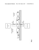 | 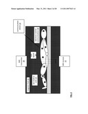 |
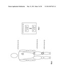 | 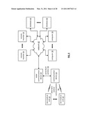 |
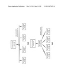 | 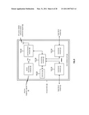 |
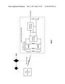 | 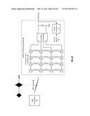 |
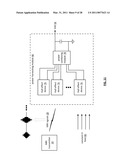 | 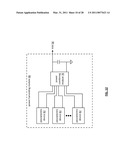 |
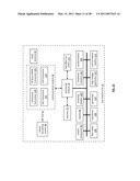 | 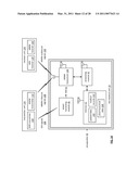 |
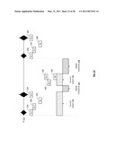 | 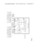 |
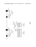 | 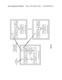 |
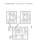 | 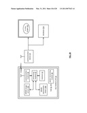 |
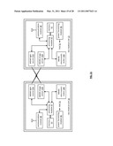 | 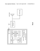 |
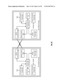 | 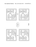 |
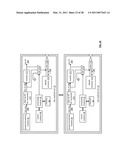 | 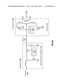 |
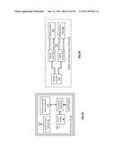 | 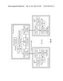 |
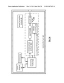 |
| Similar patent applications: | |
| Date | Title |
|---|---|
| 2009-01-01 | Programmable shunt with electromechanical valve actuator |
| 2009-09-03 | Implantable atraumatic medical site having a simplified design |
| 2010-12-23 | Ostomy faceplate having moldable adhesive wafer with diminishing surface undulations |
| 2009-06-11 | Disposable undergarment with stretch areas for optimal fit |
| 2009-12-24 | Injection device with electronic detecting means |
| New patent applications in this class: | |
| Date | Title |
|---|---|
| 2017-08-17 | Diagnostic transceiver assembly |
| 2016-07-07 | Aems compendium |
| 2016-03-17 | Microchip substance delivery devices having low-power electromechanical release mechanisms |
| 2016-03-10 | Systems, methods, and devices addressing the gastro-intestinal tract |
| 2016-01-07 | Mems device and method for delivery of therapeutic agents |
| New patent applications from these inventors: | |
| Date | Title |
|---|---|
| 2016-05-19 | Rf bus controller |
| 2015-11-19 | Portable computing device with wireless power distribution |
| 2015-11-05 | Bio-medical unit and applications for cancer treatment |
| 2015-10-01 | Wireless bus for intra-chip and inter-chip communication, including wireless-enabled component (wec) embodiments |
| 2015-08-06 | Creating a system on the fly and applications thereof |
| Top Inventors for class "Surgery" | |
| Rank | Inventor's name |
|---|---|
| 1 | Christopher Brian Locke |
| 2 | Roderick A. Hyde |
| 3 | Lowell L. Wood, Jr. |
| 4 | Timothy Mark Robinson |
| 5 | Donald Carroll Roe |