Patent application title: HEAT DISSIPATION DEVICE HAVING A FAN THEREON
Inventors:
Wei-Cheng Nie (Shenzhen City, CN)
Hong-Cheng Yang (Shenzhen City, CN)
Lei Cao (Shenzhen City, CN)
Assignees:
FU ZHUN PRECISION INDUSTRY (SHEN ZHEN) CO., LTD.
FOXCONN TECHNOLOGY CO., LTD.
IPC8 Class: AF28F1300FI
USPC Class:
165 803
Class name: With retainer for removable article electrical component air cooled, including fins
Publication date: 2010-11-25
Patent application number: 20100294463
includes a heat sink and a blower. The heat sink
has a base and a plurality of fins formed on the base. The blower
includes a frame and an impeller rotatably secured to the frame. The
frame faces and is secured to the base of the heat sink to define an
airflow passage between the base of the heat sink and the blower. An
airflow inlet is defined through the frame of the blower. Another airflow
inlet is defined through the base of the heat sink. An airflow produced
by the blower passes through the airflow passage via the airflow inlets
and then blows towards channels defined between the fins of the heat
sink.Claims:
1. A heat dissipation device comprising:a heat sink comprising a base and
a plurality of fins formed on the base; anda blower comprising a frame
and an impeller rotatably secured to the frame, the frame directly facing
and mounted to the base of the heat sink to define an airflow passage
between the base of the heat sink and the frame, the frame defining an
airflow inlet therethrough;wherein airflow produced by the blower flows
into the airflow passage via the airflow inlet and blows towards channels
defined between the fins of the heat sink from an outlet of the blower.
2. The heat dissipation device of claim 1, wherein the base of the heat sink defines another airflow inlet therethrough.
3. The heat dissipation device of claim 2, wherein the frame of the blower comprises a panel plate and a sidewall extending from a periphery thereof and engaging the base of the heat sink to secure the frame to the base of the heat sink.
4. The heat dissipation device of claim 3, wherein the impeller is located between the panel plate and the base.
5. The heat dissipation device of claim 4, wherein the impeller is secured to a bottom surface of the panel plate and surrounded by the sidewall.
6. The heat dissipation device of claim 3, wherein the frame of the blower comprises a plurality of mounting poles extending from the sidewall thereof, fasteners extending through the mounting poles of the frame of the blower and screwing into the base of the heat sink to mount the blower on the base of the heat sink.
7. The heat dissipation device of claim 6, wherein the base of the heat sink comprises a plurality of fixing portions in alignment with the mounting poles of the frame of the blower, the fasteners extending through the mounting poles and screwing into the fixing portions of the base of the heat sink.
8. The heat dissipation device of claim 1, wherein the base of the heat sink corresponding to the fins is inclined downwardly to guide the airflow of the blower to flow downwardly away from the heat dissipation device.
9. The heat dissipation device of claim 8, wherein the fins of the heat sink have gradually decreased lengths from one of two opposite lateral sides of the base of the heat sink to another of the two opposite lateral sides.
10. The heat dissipation device of claim 9, wherein the fins of the heat sink define a recessed slot in a top thereof and a guiding plate covers the fins and has a portion received in the recessed slot.
11. A heat dissipation device comprising:a heat sink having a base and a plurality of fins extending upwardly from the base;a blower covering the base of the heat sink, the blower comprising a frame facing and mounted to the base of the heat sink and an impeller rotatably secured to the frame, the frame cooperating with the base to define an airflow passage between the frame and the base, an airflow inlet being defined in the frame of the blower;wherein an airflow produced by the blower passes through the airflow passage via the airflow inlet and blows towards channels defined between the fins of the heat sink.
12. The heat dissipation device of claim 11, wherein base of the heat sink defines another airflow inlet therethrough.
13. The heat dissipation device of claim 12, wherein the base of the heat sink beneath the fins is inclined downwardly to guide the airflow to flow downwardly when the airflow leaves the heat dissipation device.Description:
BACKGROUND
[0001]1. Technical Field
[0002]The disclosure relates generally to a heat dissipation device for removing heat from an electronic component mounted on a periphery card, and particularly to a heat dissipation device comprising a blower facing a base of a heat sink in contact with the electronic component to define an airflow passage between the base of the heat sink and the blower, wherein airflow can pass through the airflow passage.
[0003]2. Description of Related Art
[0004]It is well known that during operation computer electronic devices such as central processing units (CPUs) can generate large amounts of heat. The heat must be quickly removed from the electronic device to prevent it from becoming unstable or being damaged.
[0005]Thus, a heat dissipation device which can quickly remove the heat from the electronic device is needed. Such a heat dissipation device is particularly necessary for a periphery card of a computer, for example, a video graphic array (VGA) card. A periphery card is usually crowded with other periphery cards whereby only a limited space is available for an airflow to flow through a heat sink thereof. The heat dissipation device usually includes the heat sink and a blower mounted to the heat sink. Since the periphery card has a limited space, accordingly, the heat sink is designed to have a flat-shaped base and fins with a limited height. The blower is desired to guide airflow to pass through the fins of the heat sink from one side to an opposite side thereof.
[0006]However, the blower usually includes a fan frame and a cover covering and mounted to the fan frame. Airflow produced by the blower only flows along a passage cooperatively defined by the fan frame and the cover of the blower. That is to say, when the blower is mounted to the base of the heat sink, the airflow produced by the blower fails to directly blow towards the base of the heat sink under the blower, the heat accumulated at the base of the heat sink under the blower fails to be quickly dissipated.
[0007]What is needed, therefore, is a heat dissipation device which has a blower to directly blow towards the base of the heat sink.
BRIEF DESCRIPTION OF THE DRAWINGS
[0008]Other advantages and novel features of the disclosure will become more apparent from the following detailed description of an embodiment/embodiments when taken in conjunction with the accompanying drawings.
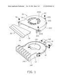
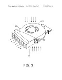
[0009]FIG. 1 is an exploded, isometric view of a heat dissipation device in accordance with an embodiment of the disclosure.
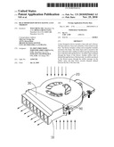
[0010]FIG. 2 is an assembled view of the heat dissipation device of FIG. 1.
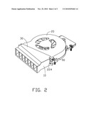
[0011]FIG. 3 is a similar view of FIG. 1, with arrows showing paths of airflow entering and leaving the heat dissipation device.
DETAILED DESCRIPTION
[0012]Referring to FIGS. 1-3, a heat dissipation device in accordance with an embodiment of the disclosure is shown. The heat dissipation device is mounted to a heat-generating electronic element (not shown) to dissipate heat from the heat-generating electronic element. Particularly, the heat-generating electronic element is a graphic processing unit (GPU) mounted on a periphery card of a computer, for example, a video graphic array (VGA) card. The heat dissipation device comprises a heat sink 10, a blower 20 and a guiding plate 30.
[0013]The heat sink 10 is integrally formed by a metal with a good heat conductivity, such as copper or aluminum. The heat sink 10 comprises a flat base 12. The base 12 comprises three portions: a first portion located in a middle of the base 12, a second portion extending forth from an end of the first portion and a third portion extending rearwards from an opposite end of the first portion. The first portion of the base 12 has a semicircular shape with a size corresponding to that of the blower 20, for supporting the blower 20 thereon. A semicircular first airflow inlet 120 is defined in the first portion of the base 12. A pair of mounting poles 16 is formed at two opposite ends of a front side of the first portion of the base 12, and another mounting pole 16 is formed on a middle portion of a top surface of the third portion of the base 12, adjacent to the rear side of the first portion of the base 12. Each mounting pole 16 defines a mounting hole 160 therein. A plurality of fins 14 are integrally formed on a top surface of the second portion of the base 12. The fins 14 have a gradually increased lengths from a left lateral side to a right lateral side of the second portion of the base 12, wherein the fins 14 are located at a position and occupy a size corresponding to those of an outlet of the blower 20. Each fin 14 defines a recessed edge at a top thereof and all recessed edges of all the fins 14 cooperatively define a recessed slot 140 in a top of the fins 14. The front side 142 of the second portion of the base 12 under the fins 14 is inclined downwardly in respect to the first portion of the base 12, wherein airflow from the outlet of the blower 20 blowing towards channels defined between the fins 14 can be guided to downwardly blow other heat-generating electronic elements mounted on the periphery card and adjacent to the front side of the base 12 of the heat sink 10.
[0014]The blower 20 comprises a frame 22 and an impeller 24. The frame 22 comprises a panel plate 220 and a lateral sidewall 222 downwardly and vertically extending from an edge side of the panel plate 220. The impeller 24 is rotatably secured to an inner surface of the panel plate 220 of the frame 22. A plurality of second airflow inlets 2200 are defined in the panel plate 220, corresponding to the first airflow inlet 120 of the base 12 of the heat sink 10. Three fixing portions 224 horizontal and outwardly extend from the lateral sidewall 222 and are evenly located along a periphery of the frame 22 of the blower 20, corresponding to the mounting poles 16 of the base 12 of the heat sink 10. Each fixing portion 224 defines a through hole 2240 therein, in alignment with the mounting hole 160 of a corresponding mounting pole 16 of the base 12 of the heat sink 10, for receiving a fastener 90 extending therethrough. The fasteners 90 extend through the through holes 2240 of the fixing portions 224 of the frame 22 of the blower 20 and screw into the mounting holes 160 of the mounting poles 16 to mount the frame 22 of the blower 20 on the first portion of the base 12 of the heat sink 10, wherein the base 12 of the heat sink 10 and the frame 22 of the blower 20 cooperatively define an airflow passage along a length direction of the base 12 of the heat sink 10 and the outlet of the blower 20 faces the channels defined between the fins 14 of the heat sink 10.
[0015]The guiding plate 30 has a size corresponding to that of a top surface of the fins 14 of the heat sink 10. The guiding plate 30 comprises a main body 32 and a recessed portion 34 extending outwardly and downwardly from a front side of the main body 32. The guiding plate 30 covers the top surface of the fins 14 with the recessed portion 34 being received in the recessed slot 140 to guide the airflow from the outlet of the blower 20 to downwardly flow to the channels defined between the fins 14 of the heat sink 10.
[0016]In operation, cooled airflow flows into the airflow passage between the frame 22 of the blower 20 and the base 12 of the heat sink 10 via the first and second airflow inlets 120, 2200, wherein the cooled airflow can directly blow a top surface of the base 12 of the heat sink 10, so heat generated by the heat-generating electronic element attached on a bottom of the base 12 of the heat sink 10 can be effectively taken away.
[0017]By provision of the frame 22 of the blower 20 engaging the base 12 of the heat sink 10, the blower 20 not only can directly blow the base 12 of the heat sink 10, but also saves a cover covering the frame 22 to define the airflow passage, whereby the cost of the blower 20 is decreased. In addition, the base 12 of the heat sink 10 defines the first airflow inlet 120 therethrough, wherein the cooled airflow flowing into the airflow passage via the first airflow inlet 120 can cause air around the heat-generating electronic element to flow through the heat-generating electronic element; thus, the heat generated by the heat-generating electronic element can be taken away as quickly as possible. Heat accumulated at the base 12 of the heat sink 10 under the blower 20 can be quickly dissipated.
[0018]It is to be understood, however, that even though numerous characteristics and advantages of the present embodiments have been set forth in the foregoing description, together with details of the structures and functions of the embodiments, the disclosure is illustrative only, and changes may be made in detail, especially in matters of shape, size, and arrangement of parts within the principles of the invention to the full extent indicated by the broad general meaning of the terms in which the appended claims are expressed.
Claims:
1. A heat dissipation device comprising:a heat sink comprising a base and
a plurality of fins formed on the base; anda blower comprising a frame
and an impeller rotatably secured to the frame, the frame directly facing
and mounted to the base of the heat sink to define an airflow passage
between the base of the heat sink and the frame, the frame defining an
airflow inlet therethrough;wherein airflow produced by the blower flows
into the airflow passage via the airflow inlet and blows towards channels
defined between the fins of the heat sink from an outlet of the blower.
2. The heat dissipation device of claim 1, wherein the base of the heat sink defines another airflow inlet therethrough.
3. The heat dissipation device of claim 2, wherein the frame of the blower comprises a panel plate and a sidewall extending from a periphery thereof and engaging the base of the heat sink to secure the frame to the base of the heat sink.
4. The heat dissipation device of claim 3, wherein the impeller is located between the panel plate and the base.
5. The heat dissipation device of claim 4, wherein the impeller is secured to a bottom surface of the panel plate and surrounded by the sidewall.
6. The heat dissipation device of claim 3, wherein the frame of the blower comprises a plurality of mounting poles extending from the sidewall thereof, fasteners extending through the mounting poles of the frame of the blower and screwing into the base of the heat sink to mount the blower on the base of the heat sink.
7. The heat dissipation device of claim 6, wherein the base of the heat sink comprises a plurality of fixing portions in alignment with the mounting poles of the frame of the blower, the fasteners extending through the mounting poles and screwing into the fixing portions of the base of the heat sink.
8. The heat dissipation device of claim 1, wherein the base of the heat sink corresponding to the fins is inclined downwardly to guide the airflow of the blower to flow downwardly away from the heat dissipation device.
9. The heat dissipation device of claim 8, wherein the fins of the heat sink have gradually decreased lengths from one of two opposite lateral sides of the base of the heat sink to another of the two opposite lateral sides.
10. The heat dissipation device of claim 9, wherein the fins of the heat sink define a recessed slot in a top thereof and a guiding plate covers the fins and has a portion received in the recessed slot.
11. A heat dissipation device comprising:a heat sink having a base and a plurality of fins extending upwardly from the base;a blower covering the base of the heat sink, the blower comprising a frame facing and mounted to the base of the heat sink and an impeller rotatably secured to the frame, the frame cooperating with the base to define an airflow passage between the frame and the base, an airflow inlet being defined in the frame of the blower;wherein an airflow produced by the blower passes through the airflow passage via the airflow inlet and blows towards channels defined between the fins of the heat sink.
12. The heat dissipation device of claim 11, wherein base of the heat sink defines another airflow inlet therethrough.
13. The heat dissipation device of claim 12, wherein the base of the heat sink beneath the fins is inclined downwardly to guide the airflow to flow downwardly when the airflow leaves the heat dissipation device.
Description:
BACKGROUND
[0001]1. Technical Field
[0002]The disclosure relates generally to a heat dissipation device for removing heat from an electronic component mounted on a periphery card, and particularly to a heat dissipation device comprising a blower facing a base of a heat sink in contact with the electronic component to define an airflow passage between the base of the heat sink and the blower, wherein airflow can pass through the airflow passage.
[0003]2. Description of Related Art
[0004]It is well known that during operation computer electronic devices such as central processing units (CPUs) can generate large amounts of heat. The heat must be quickly removed from the electronic device to prevent it from becoming unstable or being damaged.
[0005]Thus, a heat dissipation device which can quickly remove the heat from the electronic device is needed. Such a heat dissipation device is particularly necessary for a periphery card of a computer, for example, a video graphic array (VGA) card. A periphery card is usually crowded with other periphery cards whereby only a limited space is available for an airflow to flow through a heat sink thereof. The heat dissipation device usually includes the heat sink and a blower mounted to the heat sink. Since the periphery card has a limited space, accordingly, the heat sink is designed to have a flat-shaped base and fins with a limited height. The blower is desired to guide airflow to pass through the fins of the heat sink from one side to an opposite side thereof.
[0006]However, the blower usually includes a fan frame and a cover covering and mounted to the fan frame. Airflow produced by the blower only flows along a passage cooperatively defined by the fan frame and the cover of the blower. That is to say, when the blower is mounted to the base of the heat sink, the airflow produced by the blower fails to directly blow towards the base of the heat sink under the blower, the heat accumulated at the base of the heat sink under the blower fails to be quickly dissipated.
[0007]What is needed, therefore, is a heat dissipation device which has a blower to directly blow towards the base of the heat sink.
BRIEF DESCRIPTION OF THE DRAWINGS
[0008]Other advantages and novel features of the disclosure will become more apparent from the following detailed description of an embodiment/embodiments when taken in conjunction with the accompanying drawings.
[0009]FIG. 1 is an exploded, isometric view of a heat dissipation device in accordance with an embodiment of the disclosure.
[0010]FIG. 2 is an assembled view of the heat dissipation device of FIG. 1.
[0011]FIG. 3 is a similar view of FIG. 1, with arrows showing paths of airflow entering and leaving the heat dissipation device.
DETAILED DESCRIPTION
[0012]Referring to FIGS. 1-3, a heat dissipation device in accordance with an embodiment of the disclosure is shown. The heat dissipation device is mounted to a heat-generating electronic element (not shown) to dissipate heat from the heat-generating electronic element. Particularly, the heat-generating electronic element is a graphic processing unit (GPU) mounted on a periphery card of a computer, for example, a video graphic array (VGA) card. The heat dissipation device comprises a heat sink 10, a blower 20 and a guiding plate 30.
[0013]The heat sink 10 is integrally formed by a metal with a good heat conductivity, such as copper or aluminum. The heat sink 10 comprises a flat base 12. The base 12 comprises three portions: a first portion located in a middle of the base 12, a second portion extending forth from an end of the first portion and a third portion extending rearwards from an opposite end of the first portion. The first portion of the base 12 has a semicircular shape with a size corresponding to that of the blower 20, for supporting the blower 20 thereon. A semicircular first airflow inlet 120 is defined in the first portion of the base 12. A pair of mounting poles 16 is formed at two opposite ends of a front side of the first portion of the base 12, and another mounting pole 16 is formed on a middle portion of a top surface of the third portion of the base 12, adjacent to the rear side of the first portion of the base 12. Each mounting pole 16 defines a mounting hole 160 therein. A plurality of fins 14 are integrally formed on a top surface of the second portion of the base 12. The fins 14 have a gradually increased lengths from a left lateral side to a right lateral side of the second portion of the base 12, wherein the fins 14 are located at a position and occupy a size corresponding to those of an outlet of the blower 20. Each fin 14 defines a recessed edge at a top thereof and all recessed edges of all the fins 14 cooperatively define a recessed slot 140 in a top of the fins 14. The front side 142 of the second portion of the base 12 under the fins 14 is inclined downwardly in respect to the first portion of the base 12, wherein airflow from the outlet of the blower 20 blowing towards channels defined between the fins 14 can be guided to downwardly blow other heat-generating electronic elements mounted on the periphery card and adjacent to the front side of the base 12 of the heat sink 10.
[0014]The blower 20 comprises a frame 22 and an impeller 24. The frame 22 comprises a panel plate 220 and a lateral sidewall 222 downwardly and vertically extending from an edge side of the panel plate 220. The impeller 24 is rotatably secured to an inner surface of the panel plate 220 of the frame 22. A plurality of second airflow inlets 2200 are defined in the panel plate 220, corresponding to the first airflow inlet 120 of the base 12 of the heat sink 10. Three fixing portions 224 horizontal and outwardly extend from the lateral sidewall 222 and are evenly located along a periphery of the frame 22 of the blower 20, corresponding to the mounting poles 16 of the base 12 of the heat sink 10. Each fixing portion 224 defines a through hole 2240 therein, in alignment with the mounting hole 160 of a corresponding mounting pole 16 of the base 12 of the heat sink 10, for receiving a fastener 90 extending therethrough. The fasteners 90 extend through the through holes 2240 of the fixing portions 224 of the frame 22 of the blower 20 and screw into the mounting holes 160 of the mounting poles 16 to mount the frame 22 of the blower 20 on the first portion of the base 12 of the heat sink 10, wherein the base 12 of the heat sink 10 and the frame 22 of the blower 20 cooperatively define an airflow passage along a length direction of the base 12 of the heat sink 10 and the outlet of the blower 20 faces the channels defined between the fins 14 of the heat sink 10.
[0015]The guiding plate 30 has a size corresponding to that of a top surface of the fins 14 of the heat sink 10. The guiding plate 30 comprises a main body 32 and a recessed portion 34 extending outwardly and downwardly from a front side of the main body 32. The guiding plate 30 covers the top surface of the fins 14 with the recessed portion 34 being received in the recessed slot 140 to guide the airflow from the outlet of the blower 20 to downwardly flow to the channels defined between the fins 14 of the heat sink 10.
[0016]In operation, cooled airflow flows into the airflow passage between the frame 22 of the blower 20 and the base 12 of the heat sink 10 via the first and second airflow inlets 120, 2200, wherein the cooled airflow can directly blow a top surface of the base 12 of the heat sink 10, so heat generated by the heat-generating electronic element attached on a bottom of the base 12 of the heat sink 10 can be effectively taken away.
[0017]By provision of the frame 22 of the blower 20 engaging the base 12 of the heat sink 10, the blower 20 not only can directly blow the base 12 of the heat sink 10, but also saves a cover covering the frame 22 to define the airflow passage, whereby the cost of the blower 20 is decreased. In addition, the base 12 of the heat sink 10 defines the first airflow inlet 120 therethrough, wherein the cooled airflow flowing into the airflow passage via the first airflow inlet 120 can cause air around the heat-generating electronic element to flow through the heat-generating electronic element; thus, the heat generated by the heat-generating electronic element can be taken away as quickly as possible. Heat accumulated at the base 12 of the heat sink 10 under the blower 20 can be quickly dissipated.
[0018]It is to be understood, however, that even though numerous characteristics and advantages of the present embodiments have been set forth in the foregoing description, together with details of the structures and functions of the embodiments, the disclosure is illustrative only, and changes may be made in detail, especially in matters of shape, size, and arrangement of parts within the principles of the invention to the full extent indicated by the broad general meaning of the terms in which the appended claims are expressed.
User Contributions:
Comment about this patent or add new information about this topic:
Images included with this patent application:
 |  |
 |  |
| Similar patent applications: | |
| Date | Title |
|---|---|
| 2013-01-10 | Heat dissipation unit and manufacturing method thereof and thermal module thereof |
| 2010-02-04 | Heat dissipation utilizing flow of refrigerant |
| 2012-12-13 | Apparatus for heat dissipation of transforming radiators |
| 2008-10-09 | Reduced vibration tube bundle device having slotted baffles |
| 2010-11-25 | Heat dissipating device for memory card |
| New patent applications in this class: | |
| Date | Title |
|---|---|
| 2019-05-16 | Heat dissipation module |
| 2018-01-25 | Methods and apparatus for rapidly cooling a substrate |
| 2016-12-29 | Heat sink, method for making the same, and electronic device having the same |
| 2016-06-23 | Kinetic heat-sink with interdigitated heat-transfer fins |
| 2016-06-23 | Multi-phase elastomeric thermally conductive materials |
| New patent applications from these inventors: | |
| Date | Title |
|---|---|
| 2011-06-30 | Locking structure and method for manufacturing the same and heat dissipation device using the same |
| 2011-06-23 | Fan holder and heat dissipation device using the same |
| 2011-06-23 | Heat dissipation device |
| Top Inventors for class "Heat exchange" | |
| Rank | Inventor's name |
|---|---|
| 1 | Levi A. Campbell |
| 2 | Chun-Chi Chen |
| 3 | Tai-Her Yang |
| 4 | Robert E. Simons |
| 5 | Richard C. Chu |