Patent application title: Longitudinal and Lateral Velocity Estimation Using Single Antenna GPS and Magnetic Compass
Inventors:
Flavio Nardi (Farmington Hills, MI, US)
Nikolai K. Moshchuk (Grosse Pointe, MI, US)
Jihan Ryu (Rochester Hills, MI, US)
Kevin A. O'Dea (Ann Arbor, MI, US)
Assignees:
GM GLOBAL TECHNOLOGY OPERATIONS, INC.
IPC8 Class: AG01S100FI
USPC Class:
34235709
Class name: With position indicating using global positioning satellite (gps or glonass) with transmission of location-indicative information to or from a remote station
Publication date: 2010-08-26
Patent application number: 20100214164
ovided for determining a lateral velocity and a
longitudinal velocity of a vehicle equipped. The vehicle includes only
one antenna for a GPS receiver and a magnetic compass. A magnitude of a
velocity vector of the vehicle is determined. A course angle with respect
to a fixed reference using the single antenna GPS receiver is determined.
A yaw angle of the vehicle is measured with respect to the fixed
reference using a magnetic compass. A side slip angle is calculated as a
function of the course angle and the yaw angle. The lateral velocity and
longitudinal velocity is determined as a function of the magnitude of the
velocity vector and the side slip angle.Claims:
1. A method for determining lateral velocity and longitudinal velocity of
a vehicle equipped with a single antenna GPS receiver and a magnetic
compass, the method comprising the steps of:determining a velocity of the
vehicle;determining a direction of travel in relation to a predetermined
point on the vehicle using GPS;measuring a longitudinal orientation of
the vehicle using a magnetic compass; anddetermining the lateral velocity
and longitudinal velocity each as a function of the magnitude of the
velocity vector, and an angle between the direction of travel and the
longitudinal orientation.
2. The method of claim 1 wherein the angle is a side slip angle determined as a function of the determined direction of travel in relation to the predetermined point and the longitudinal orientation of the vehicle, the side slip angle being represented by the following formula:β=γ-.psi.where β is the side slip angle, γ is the determined direction of travel in relation to the predetermined point, and ψ is the longitudinal orientation of the vehicle.
3. The method of claim 2 wherein the lateral velocity is determined by the following formula:vx=|V| cos βwhere vx is the lateral velocity, and V is the velocity of the vehicle.
4. The method of claim 2 wherein the lateral velocity is determined by the following formula:vy=|V|sin βwhere vy is the longitudinal velocity, and V is the velocity of the vehicle.
5. The method of claim 1 wherein the longitudinal orientation of the vehicle body is measured using a digital magnetic compass.
6. The method of claim 1 wherein the predetermined point used to determine direction of travel includes a reference vector pointing due North.
7. A method for determining a lateral velocity and a longitudinal velocity of a vehicle equipped, the vehicle including only one antenna for a GPS receiver and a magnetic compass, the method comprising the steps of:determining a magnitude of a velocity vector of the vehicle;determining a course angle with respect to a fixed reference using the single antenna GPS receiver;measuring a yaw angle of the vehicle with respect to the fixed reference using a magnetic compass;calculating a side slip angle as a function of the course angle and the yaw angle; anddetermining the lateral velocity and longitudinal velocity as a function of the magnitude of the velocity vector and the side slip angle.
8. The method of claim 7 wherein the side slip angle is determined as a function of the course angle and the yaw angle, the side slip angle being represented by the following formula:β=γ-.psi.where β is the side slip angle, γ is the course angle, and ψ is the yaw angle of the vehicle body.
9. The method of claim 2 wherein the lateral velocity is determined by the following formula:vx=|V|cos βwhere vx is the lateral velocity, and V is the velocity vector.
10. The method of claim 2 wherein the lateral velocity is determined by the following formula:vy=|V|sin βwhere vy is the longitudinal velocity, and V is the velocity vector.
11. A vehicle dynamic control system for determining vehicle dynamic parameters for a vehicle, the system comprising:a global positioning system (GPS) receiver having only a single antenna, the GPS receiver receiving course angle data of the vehicle;a magnetic compass for providing yaw angle data of the vehicle; anda controller determining a side slip angle in response to the yaw angle data and the course angle data;wherein the controller determines a longitudinal velocity and a lateral velocity as a function of the side slip angle.
12. The system of claim 11 wherein the magnetic compass is integrated with the GPS receiver.
13. The system of claim 11 further comprising a speed sensor for providing speed data to the controller for determining the longitudinal velocity and the lateral velocity.
14. The system of claim 11 where the GPS receiver determines a vehicle speed.
15. The system of claim 11 wherein the controller determines a slide slip angle of the vehicle utilizing the following formula:β=γ-.psi.where β is the side slip angle, γ is the azimuth angle of the velocity vector, and ψ is the azimuth angle of the vehicle body.
16. The system of claim 15 wherein the lateral velocity is determined by the controller using the following formula:vx=|V|cos βwhere vx is the lateral velocity, and V is the velocity of the vehicle.
17. The system of claim 15 wherein the longitudinal velocity is determined by the controller using the following formula:vy=|V|sin βwhere vy is the longitudinal velocity, and V is the velocity of the vehicle.
18. The system of claim 11 wherein the magnetic compass is a digital magnetic compass.Description:
BACKGROUND OF INVENTION
[0001]An embodiment relates generally to vehicle dynamics control. Longitudinal velocity and lateral velocity are vehicle dynamic variables used by vehicle control systems. Longitudinal speed is a vehicle dynamic variable used for example by adaptive cruise control systems and anti-lock braking systems. Lateral velocity is a vehicle dynamic variable used for stability control systems.
[0002]Longitudinal and lateral velocity measurements are generally measured via wheel speed sensors, and/or lateral acceleration sensors, and/or other inertia-based sensors. Often such sensors must be calibrated for sensor bias or the use of sensors having high accuracy must be utilized.
[0003]An optical sensor or a multi-antenna global positioning system (GPS) receiver can provide longitudinal and lateral velocity measurements. Multi-antenna GPS receivers utilize at least two antennas. The antennas must be spaced from one another. The multi-antenna GPS receiver estimates vehicle position, velocity, acceleration, attitude, and angular rates at both antennas and compares them to determine lateral and longitudinal velocities. However, a two-antenna GPS receiver is expensive. Various other measurement devices described above are either costly and/or are computationally intensive for determining the longitudinal and lateral velocities of the vehicle.
SUMMARY OF INVENTION
[0004]An advantage of an embodiment is the determination of the lateral velocity and longitudinal velocity utilizing a single antenna vehicle GPS system and magnetic compass that requires simple computations.
[0005]An embodiment contemplates a method for determining a lateral velocity and a longitudinal velocity of a vehicle. The vehicle includes only one antenna for a GPS receiver and a magnetic compass. The magnitude of the velocity vector of the vehicle is determined using the single antenna GPS receiver. A course angle with respect to a fixed reference (i.e., an inertial (earth fixed) reference frame) using the single antenna GPS receiver is determined). A yaw angle of the vehicle is measured with respect to the fixed reference (i.e., an inertial (earth fixed) reference frame) using a magnetic compass). A side slip angle is calculated as a function of the course angle and the yaw angle. The lateral velocity and longitudinal velocity is determined as a function of the magnitude of the velocity vector and the side slip angle.
[0006]An embodiment contemplates a method for determining lateral velocity and longitudinal velocity of a vehicle equipped with a single antenna GPS receiver and a magnetic compass. A velocity of the vehicle is determined. A direction of travel of a predetermined point using GPS on the vehicle is determined. A longitudinal orientation of the vehicle is measured using a magnetic compass. The lateral velocity and longitudinal velocity are determined each as a function of the magnitude of the velocity vector, and an angle between the direction of travel and the longitudinal orientation.
BRIEF DESCRIPTION OF DRAWINGS
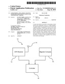
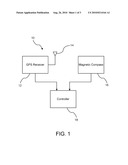
[0007]FIG. 1 is a block diagram of the GPS assisted vehicular longitudinal and lateral velocity determination system.
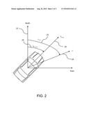
[0008]FIG. 2 is a positional view of a vehicle illustrating yaw and course angle travel of a vehicle.
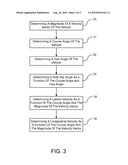
[0009]FIG. 3 is a flowchart of a method for determining vehicle dynamic variables.
DETAILED DESCRIPTION
[0010]There is shown in FIG. 1 a block diagram of a GPS assisted vehicular longitudinal and lateral velocity determination system 10. The system 10 is used to determine a vehicle lateral velocity and a longitudinal velocity of a vehicle. Longitudinal velocity is a velocity of a vehicle as it moves in a forward direction. Lateral velocity is a speed of a lateral movement of a vehicle as it transitions through a turn or travels along a curved path. Various devices and methods have been used to determine both lateral and longitudinal velocities, but such devices may include costly sensors, are computationally complex, or provide data with errors.
[0011]FIGS. 1-2 will be used in cooperation to describe the system 10 and the various directional measurements obtained by the system 10. The system 10 includes a GPS receiver 12 coupled to a single antenna 14, a magnetic compass 16, and a controller 18.
[0012]The GPS receiver 12 utilizes a constellation of satellites that transmit signals which enable the GPS receiver 12 of a vehicle to determine the vehicle's location, speed, direction, and time. Based on the GPS data, a course angle (γGPS) 20 is determined. The course angle 20 is a direction of travel over a surface of the Earth with respect to a predetermined point which is typically the north pole. That is, the course angle is expressed as the angle measured from a virtual vector pointing due North 22 to a direction of travel of the vehicle which is represented by a centerline of the body axis (XBody) 24. The course angle 20 is the angular difference between the virtual vector pointing due North 22 and a vehicle's heading (V) 28.
[0013]A magnetic compass 16 is provided for measuring a yaw angle (ΨCompass) 26. The yaw angle 26 is defined as an angle between a centerline of the body axis (XBody) 24 and reference heading (i.e., the virtual vector pointing due North 22). The magnetic compass 16 may include a digital magnetic compass for obtaining fast response times and being unaffected by sudden vehicle movement and environmental conditions. Additional integrated inertial sensors may be used to remove the effects of such conditions. The magnetic compass 16 may be integrated with the GPS receiver 12 as a single unit or as part of a single chip. Whether a magnetic compass 16 and the GPS receiver 12 are integrated or non-integrated, one antenna is only required for the determination of the longitudinal velocity and lateral velocity.
[0014]A controller 18 is in communication with the GPS receiver 12 and the magnetic compass 16. The controller 18 determines a side slip angle as a function of the course angle and yaw angle. The controller 18 may be a stand-alone controller or may be a controller that is part of another system since minimal computations and processing are required. For example, a controller may include, but is not limited to, the controller of a GPS receiver, a digital magnetic compass, an electronic control unit, or a body control unit.
[0015]The side slip angle is a deviation of the vehicle's centerline from its original path of travel to its displaced path of travel as the vehicle transitions through a curve or turn. The controller 18 determines the side slip angle by the difference between the course angle 20 and the yaw angle 26. The side slip angle is represented by the following equation:
β=γGPS-ΨCompass (1)
where β is the side slip angle, γGPS is the course angle, and ΨCompass is yaw angle.
[0016]Once the side slip angle is determined, the longitudinal velocity and the lateral velocity may be determined as a function of the side slip angle β and vehicle speed V using trigonometric functions.
[0017]The formula for determining the lateral velocity vx is represented by:
xx=|V|cos β (2)
where vx is the lateral velocity, is V the vehicle velocity, and β is the side slip angle.
[0018]The formula for determining the lateral velocity vy is represented by:
vy=|V|sin β (3)
where vy is the lateral velocity, V the vehicle velocity, and β is the sides slip angle.
[0019]As a result, lateral velocity vx and longitudinal velocity vy may be easily calculated utilizing non-complex equations which may be computed in a time efficient manner resulting in fast response times.
[0020]FIG. 3 illustrates a flowchart of a method for determining the lateral velocity and longitudinal velocity of the vehicle. In step 30, the vehicle speed of the vehicle is determined (i.e., magnitude of a velocity vector). The vehicle speed may be determined using various devices which may include, but is not limited to, GPS data, a wheel speed sensor, or engine control unit data.
[0021]In step 31, a course angle of the vehicle is determined. The course angle is determined based on the GPS data. The course angle is the direction of travel over a surface of the Earth with respect to a predetermined point which is typically the vector pointing due North.
[0022]In step 32, a yaw angle of the vehicle is determined. The yaw angle is determined using a magnetic compass. The yaw angle is the angle between a centerline of the body axis (XBody) 24 and a due North reference heading. A digital compass may be used which is unaffected by sudden vehicle movements and environmental conditions.
[0023]In step 33, the side slip angle is determined by calculating the difference between the course angle as determined by the single antenna GPS receiver and the yaw angle as determined by the magnetic compass. In step 34, a lateral velocity is determined as a function of the course angle and the magnitude of the speed by the formula represented in eq. (2).
[0024]In step 34, a longitudinal velocity is determined as a function of the yaw angle and the magnitude of the speed by the formula represented in eq. (3). While certain embodiments of the present invention have been described in detail, those familiar with the art to which this invention relates will recognize various alternative designs and embodiments for practicing the invention as defined by the following claims.
Claims:
1. A method for determining lateral velocity and longitudinal velocity of
a vehicle equipped with a single antenna GPS receiver and a magnetic
compass, the method comprising the steps of:determining a velocity of the
vehicle;determining a direction of travel in relation to a predetermined
point on the vehicle using GPS;measuring a longitudinal orientation of
the vehicle using a magnetic compass; anddetermining the lateral velocity
and longitudinal velocity each as a function of the magnitude of the
velocity vector, and an angle between the direction of travel and the
longitudinal orientation.
2. The method of claim 1 wherein the angle is a side slip angle determined as a function of the determined direction of travel in relation to the predetermined point and the longitudinal orientation of the vehicle, the side slip angle being represented by the following formula:β=γ-.psi.where β is the side slip angle, γ is the determined direction of travel in relation to the predetermined point, and ψ is the longitudinal orientation of the vehicle.
3. The method of claim 2 wherein the lateral velocity is determined by the following formula:vx=|V| cos βwhere vx is the lateral velocity, and V is the velocity of the vehicle.
4. The method of claim 2 wherein the lateral velocity is determined by the following formula:vy=|V|sin βwhere vy is the longitudinal velocity, and V is the velocity of the vehicle.
5. The method of claim 1 wherein the longitudinal orientation of the vehicle body is measured using a digital magnetic compass.
6. The method of claim 1 wherein the predetermined point used to determine direction of travel includes a reference vector pointing due North.
7. A method for determining a lateral velocity and a longitudinal velocity of a vehicle equipped, the vehicle including only one antenna for a GPS receiver and a magnetic compass, the method comprising the steps of:determining a magnitude of a velocity vector of the vehicle;determining a course angle with respect to a fixed reference using the single antenna GPS receiver;measuring a yaw angle of the vehicle with respect to the fixed reference using a magnetic compass;calculating a side slip angle as a function of the course angle and the yaw angle; anddetermining the lateral velocity and longitudinal velocity as a function of the magnitude of the velocity vector and the side slip angle.
8. The method of claim 7 wherein the side slip angle is determined as a function of the course angle and the yaw angle, the side slip angle being represented by the following formula:β=γ-.psi.where β is the side slip angle, γ is the course angle, and ψ is the yaw angle of the vehicle body.
9. The method of claim 2 wherein the lateral velocity is determined by the following formula:vx=|V|cos βwhere vx is the lateral velocity, and V is the velocity vector.
10. The method of claim 2 wherein the lateral velocity is determined by the following formula:vy=|V|sin βwhere vy is the longitudinal velocity, and V is the velocity vector.
11. A vehicle dynamic control system for determining vehicle dynamic parameters for a vehicle, the system comprising:a global positioning system (GPS) receiver having only a single antenna, the GPS receiver receiving course angle data of the vehicle;a magnetic compass for providing yaw angle data of the vehicle; anda controller determining a side slip angle in response to the yaw angle data and the course angle data;wherein the controller determines a longitudinal velocity and a lateral velocity as a function of the side slip angle.
12. The system of claim 11 wherein the magnetic compass is integrated with the GPS receiver.
13. The system of claim 11 further comprising a speed sensor for providing speed data to the controller for determining the longitudinal velocity and the lateral velocity.
14. The system of claim 11 where the GPS receiver determines a vehicle speed.
15. The system of claim 11 wherein the controller determines a slide slip angle of the vehicle utilizing the following formula:β=γ-.psi.where β is the side slip angle, γ is the azimuth angle of the velocity vector, and ψ is the azimuth angle of the vehicle body.
16. The system of claim 15 wherein the lateral velocity is determined by the controller using the following formula:vx=|V|cos βwhere vx is the lateral velocity, and V is the velocity of the vehicle.
17. The system of claim 15 wherein the longitudinal velocity is determined by the controller using the following formula:vy=|V|sin βwhere vy is the longitudinal velocity, and V is the velocity of the vehicle.
18. The system of claim 11 wherein the magnetic compass is a digital magnetic compass.
Description:
BACKGROUND OF INVENTION
[0001]An embodiment relates generally to vehicle dynamics control. Longitudinal velocity and lateral velocity are vehicle dynamic variables used by vehicle control systems. Longitudinal speed is a vehicle dynamic variable used for example by adaptive cruise control systems and anti-lock braking systems. Lateral velocity is a vehicle dynamic variable used for stability control systems.
[0002]Longitudinal and lateral velocity measurements are generally measured via wheel speed sensors, and/or lateral acceleration sensors, and/or other inertia-based sensors. Often such sensors must be calibrated for sensor bias or the use of sensors having high accuracy must be utilized.
[0003]An optical sensor or a multi-antenna global positioning system (GPS) receiver can provide longitudinal and lateral velocity measurements. Multi-antenna GPS receivers utilize at least two antennas. The antennas must be spaced from one another. The multi-antenna GPS receiver estimates vehicle position, velocity, acceleration, attitude, and angular rates at both antennas and compares them to determine lateral and longitudinal velocities. However, a two-antenna GPS receiver is expensive. Various other measurement devices described above are either costly and/or are computationally intensive for determining the longitudinal and lateral velocities of the vehicle.
SUMMARY OF INVENTION
[0004]An advantage of an embodiment is the determination of the lateral velocity and longitudinal velocity utilizing a single antenna vehicle GPS system and magnetic compass that requires simple computations.
[0005]An embodiment contemplates a method for determining a lateral velocity and a longitudinal velocity of a vehicle. The vehicle includes only one antenna for a GPS receiver and a magnetic compass. The magnitude of the velocity vector of the vehicle is determined using the single antenna GPS receiver. A course angle with respect to a fixed reference (i.e., an inertial (earth fixed) reference frame) using the single antenna GPS receiver is determined). A yaw angle of the vehicle is measured with respect to the fixed reference (i.e., an inertial (earth fixed) reference frame) using a magnetic compass). A side slip angle is calculated as a function of the course angle and the yaw angle. The lateral velocity and longitudinal velocity is determined as a function of the magnitude of the velocity vector and the side slip angle.
[0006]An embodiment contemplates a method for determining lateral velocity and longitudinal velocity of a vehicle equipped with a single antenna GPS receiver and a magnetic compass. A velocity of the vehicle is determined. A direction of travel of a predetermined point using GPS on the vehicle is determined. A longitudinal orientation of the vehicle is measured using a magnetic compass. The lateral velocity and longitudinal velocity are determined each as a function of the magnitude of the velocity vector, and an angle between the direction of travel and the longitudinal orientation.
BRIEF DESCRIPTION OF DRAWINGS
[0007]FIG. 1 is a block diagram of the GPS assisted vehicular longitudinal and lateral velocity determination system.
[0008]FIG. 2 is a positional view of a vehicle illustrating yaw and course angle travel of a vehicle.
[0009]FIG. 3 is a flowchart of a method for determining vehicle dynamic variables.
DETAILED DESCRIPTION
[0010]There is shown in FIG. 1 a block diagram of a GPS assisted vehicular longitudinal and lateral velocity determination system 10. The system 10 is used to determine a vehicle lateral velocity and a longitudinal velocity of a vehicle. Longitudinal velocity is a velocity of a vehicle as it moves in a forward direction. Lateral velocity is a speed of a lateral movement of a vehicle as it transitions through a turn or travels along a curved path. Various devices and methods have been used to determine both lateral and longitudinal velocities, but such devices may include costly sensors, are computationally complex, or provide data with errors.
[0011]FIGS. 1-2 will be used in cooperation to describe the system 10 and the various directional measurements obtained by the system 10. The system 10 includes a GPS receiver 12 coupled to a single antenna 14, a magnetic compass 16, and a controller 18.
[0012]The GPS receiver 12 utilizes a constellation of satellites that transmit signals which enable the GPS receiver 12 of a vehicle to determine the vehicle's location, speed, direction, and time. Based on the GPS data, a course angle (γGPS) 20 is determined. The course angle 20 is a direction of travel over a surface of the Earth with respect to a predetermined point which is typically the north pole. That is, the course angle is expressed as the angle measured from a virtual vector pointing due North 22 to a direction of travel of the vehicle which is represented by a centerline of the body axis (XBody) 24. The course angle 20 is the angular difference between the virtual vector pointing due North 22 and a vehicle's heading (V) 28.
[0013]A magnetic compass 16 is provided for measuring a yaw angle (ΨCompass) 26. The yaw angle 26 is defined as an angle between a centerline of the body axis (XBody) 24 and reference heading (i.e., the virtual vector pointing due North 22). The magnetic compass 16 may include a digital magnetic compass for obtaining fast response times and being unaffected by sudden vehicle movement and environmental conditions. Additional integrated inertial sensors may be used to remove the effects of such conditions. The magnetic compass 16 may be integrated with the GPS receiver 12 as a single unit or as part of a single chip. Whether a magnetic compass 16 and the GPS receiver 12 are integrated or non-integrated, one antenna is only required for the determination of the longitudinal velocity and lateral velocity.
[0014]A controller 18 is in communication with the GPS receiver 12 and the magnetic compass 16. The controller 18 determines a side slip angle as a function of the course angle and yaw angle. The controller 18 may be a stand-alone controller or may be a controller that is part of another system since minimal computations and processing are required. For example, a controller may include, but is not limited to, the controller of a GPS receiver, a digital magnetic compass, an electronic control unit, or a body control unit.
[0015]The side slip angle is a deviation of the vehicle's centerline from its original path of travel to its displaced path of travel as the vehicle transitions through a curve or turn. The controller 18 determines the side slip angle by the difference between the course angle 20 and the yaw angle 26. The side slip angle is represented by the following equation:
β=γGPS-ΨCompass (1)
where β is the side slip angle, γGPS is the course angle, and ΨCompass is yaw angle.
[0016]Once the side slip angle is determined, the longitudinal velocity and the lateral velocity may be determined as a function of the side slip angle β and vehicle speed V using trigonometric functions.
[0017]The formula for determining the lateral velocity vx is represented by:
xx=|V|cos β (2)
where vx is the lateral velocity, is V the vehicle velocity, and β is the side slip angle.
[0018]The formula for determining the lateral velocity vy is represented by:
vy=|V|sin β (3)
where vy is the lateral velocity, V the vehicle velocity, and β is the sides slip angle.
[0019]As a result, lateral velocity vx and longitudinal velocity vy may be easily calculated utilizing non-complex equations which may be computed in a time efficient manner resulting in fast response times.
[0020]FIG. 3 illustrates a flowchart of a method for determining the lateral velocity and longitudinal velocity of the vehicle. In step 30, the vehicle speed of the vehicle is determined (i.e., magnitude of a velocity vector). The vehicle speed may be determined using various devices which may include, but is not limited to, GPS data, a wheel speed sensor, or engine control unit data.
[0021]In step 31, a course angle of the vehicle is determined. The course angle is determined based on the GPS data. The course angle is the direction of travel over a surface of the Earth with respect to a predetermined point which is typically the vector pointing due North.
[0022]In step 32, a yaw angle of the vehicle is determined. The yaw angle is determined using a magnetic compass. The yaw angle is the angle between a centerline of the body axis (XBody) 24 and a due North reference heading. A digital compass may be used which is unaffected by sudden vehicle movements and environmental conditions.
[0023]In step 33, the side slip angle is determined by calculating the difference between the course angle as determined by the single antenna GPS receiver and the yaw angle as determined by the magnetic compass. In step 34, a lateral velocity is determined as a function of the course angle and the magnitude of the speed by the formula represented in eq. (2).
[0024]In step 34, a longitudinal velocity is determined as a function of the yaw angle and the magnitude of the speed by the formula represented in eq. (3). While certain embodiments of the present invention have been described in detail, those familiar with the art to which this invention relates will recognize various alternative designs and embodiments for practicing the invention as defined by the following claims.
User Contributions:
Comment about this patent or add new information about this topic:
| People who visited this patent also read: | |
| Patent application number | Title |
|---|---|
| 20140355295 | UNIFORM ILLUMINATION LIGHT DIFFUSING FIBER DEVICE |
| 20140355294 | FIRE-PROOF ILLUMINATING WEB, FIRE-PROOF ILLUMINATING STRUCTURE, THEIR MANUFACTURING PROCESSES AND THEIR USE |
| 20140355293 | INDIRECT LIGHTING APPARATUS |
| 20140355292 | Fiber Optic Filament Lamp |
| 20140355291 | LIGHT GUIDE AND ILLUMINATION DEVICE |
Images included with this patent application:
 |  |
 |  |
| New patent applications in this class: | |
| Date | Title |
|---|---|
| 2010-08-19 | Rideshare system and associated methodology |
| 2010-08-05 | Method and apparatus for position determination with hybrid sps orbit data |
| 2010-07-22 | Method and apparatus for providing a global secure user plane location (supl) service |
| 2010-07-08 | System and method for wireless positioning and location determination |
| 2010-07-08 | Electronic apparatus and image display method |
| New patent applications from these inventors: | |
| Date | Title |
|---|---|
| 2022-09-01 | Pro-active trajectory tracking control for automated driving during elevation transitions |
| 2022-07-14 | Selecting trajectories for controlling autonomous vehicles |
| 2022-06-30 | Consideration of acceleration lag in lead vehicle to enhance host vehicle operation |
| 2021-12-02 | Method and apparatus for determining a velocity of a vehicle |
| Top Inventors for class "Communications: directive radio wave systems and devices (e.g., radar, radio navigation)" | |
| Rank | Inventor's name |
|---|---|
| 1 | Charles Abraham |
| 2 | Frank Van Diggelen |
| 3 | Dominic Gerard Farmer |
| 4 | Farshid Alizadeh-Shabdiz |
| 5 | Ulrich Vollath |