Patent application title: METHOD FOR MANUFACTURING HOSE COUPLINGS
Inventors:
Tsan-Jee Chen (Taipei, TW)
IPC8 Class: AB22D1700FI
USPC Class:
164113
Class name: Process shaping liquid metal against a forming surface pressure forming
Publication date: 2009-12-17
Patent application number: 20090308561
g hose couplings is composed of three steps as
follows. The first step involves jointing and fixing a top casting-cavity
insert and a bottom casting-cavity insert within a mold base of a casting
machine. The second step is injecting a high-temperature molten metal
into both the casting-cavity inserts, so that the molten metal can fill
up the casting-cavity inserts. The third step is cooling the
casting-cavity inserts by using a cooling liquid, so that the cooled and
solidified metal can be released from the casting-cavity inserts to form
a hose coupling. By using the method, various types of top casting-cavity
inserts and bottom casting-cavity inserts may be adapted as desired and,
therefore, various types of hose couplings may be manufactured as
desired.Claims:
1. A method for manufacturing hose couplings, making various types of top
casting-cavity inserts and bottom casting-cavity inserts adapted as
desired so as to give various types of hose couplings, the method
comprising steps:jointing and fixing a top casting-cavity insert and a
bottom casting-cavity insert within a mold base of a casting
machine;injecting a high-temperature molten metal from a furnace into
both the casting-cavity inserts, so that the molten metal can fill up the
casting-cavity inserts; andreleasing the solidified metal from the
casting-cavity inserts to form a hose coupling.
2. The method according claim 1, wherein the molten metal is injected through an automatic machine or manually into both the casting-cavity inserts.
3. The method according claim 1, wherein the molten metal is aluminum.
4. The method according claim 1, wherein the molten metal is copper.
5. The method according claim 1, wherein the molten metal is iron.
6. The method according claim 1, wherein the molten metal is steel.
7. A method for manufacturing hose couplings, making various types of top casting-cavity inserts and bottom casting-cavity inserts adapted as desired so as to give various types of hose couplings, the method comprising steps:jointing and fixing a top casting-cavity insert and a bottom casting-cavity insert within a mold base of a casting machine;injecting a high-temperature molten metal from a furnace into both the casting-cavity inserts, so that the molten metal can fill up the casting-cavity inserts;cooling both the casting-cavity inserts by using a cooling liquid, so that the molten metal within both the casting-cavity inserts can be cooled and solidified; releasing the solidified metal from the casting-cavity inserts to form a hose coupling.
8. The method according claim 7, wherein the molten metal is injected through an automatic machine or manually into both the casting-cavity inserts.
9. The method according claim 7, wherein the molten metal is aluminum.
10. The method according claim 7, wherein the molten metal is copper.
11. The method according claim 7, wherein the molten metal is iron.
12. The method according claim 7, wherein the molten metal is steel.Description:
BACKGROUND OF THE INVENTION
[0001]1. Field of the invention
[0002]The present invention relates to a method for manufacturing hose couplings and, particularly, to a method for manufacturing hose couplings that can manufacture various types of hose couplings by utilizing a characteristic capability of adapting two casting-cavity inserts as desired.
[0003]2. Description of the Prior Art
[0004]Conventional manufacture of hose couplings mainly uses casting molds for performing the process of casting. However, there is a large variety of conventional types of hose couplings; therefore, various molds must be made as desired. Moreover, if some other types of couplings are required later, an increasing number of molds will be needed. All these molds not only take up a lot of space, but they also require much capital expenditure to finance the development of all these molds. Thus, the more molds required, the higher the relative cost is. This is, indeed, a burden to the manufacturer.
[0005]Since the conventional method has such drawbacks as described above, it is hardly a good one. An improvement is required urgently.
[0006]In view of the above difficulties associated with the conventional manufacture of hose couplings, the present inventor, through a long-term study and practice, has set about the work of improvement and innovation that provides the present method for manufacturing host couplings.
SUMMARY OF THE INVENTION
[0007]The primary aspect of the present invention is to provide a method for manufacturing hose couplings that can manufacture various types of hose couplings by adapting and replacing various top and bottom casting-cavity inserts as desired.
[0008]Another aspect of the present invention is to provide a method for manufacturing hose couplings by utilizing a characteristic capability of adapting two casting-cavity inserts as desired to decrease the number of molds required, so as to reduce the space needed to store the molds. The method is different from the conventional method, in which couplings are made with one mold for one type of coupling. As a result, with more molds being made, more space is used for storing the molds.
[0009]A method for manufacturing hose couplings to fulfill the aspects of the present invention comprises three steps. The first step involves jointing and fixing a top casting-cavity insert and a bottom casting-cavity insert within a mold base of a casting machine. The second step is injecting a high-temperature molten metal into both the casting-cavity inserts, so that the molten metal may flow to and fill up the cavities within the casting-cavity inserts. The third step is to cool the casting-cavity inserts by using a cooling liquid, so that the molten metal within the casting-cavity inserts may solidify to form a hose coupling after a cooling period. By using the method described above, various top casting-cavity inserts and bottom casting-cavity inserts may be adapted as desired and, therefore, various types of hose couplings may be manufactured by utilizing the characteristic capability of replacing two casting-cavity inserts as desired.
[0010]These features and advantages of the present invention will be fully understood and appreciated from the following detailed description of the accompanying Drawings.
BRIEF DESCRIPTION OF THE DRAWINGS
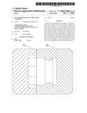
[0011]FIG. 1A and 1B are, respectively, schematic diagrams for the flow of manufacture and the product in one embodiment of the present invention.
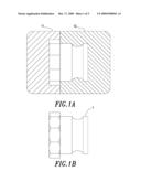
[0012]FIG. 2A and 2B are, respectively, schematic diagrams for the flow of manufacture and the product in another one embodiment of the present invention.
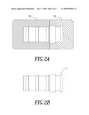
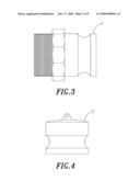
[0013]FIG. 3-8 are schematic diagrams for other products according to the method for manufacturing hose couplings according to the present invention.
DESCRIPTION OF THE PREFERRED EMBODIMENT
[0014]Referring to FIG. 1A and 1B, which are, respectively, schematic diagrams for the flow of manufacture and the product in one embodiment of the method for manufacturing hose couplings according to the present invention, the method comprises the following steps: jointing and fixing a top casting-cavity insert 11 and a bottom casting-cavity insert 12 within a mold base of a casting machine; injecting a high-temperature molten metal from a furnace through an automatic machine or manually into both the casting-cavity inserts 11 and 12, so that the molten metal may fill up the cavities within the casting-cavity inserts 11 and 12, wherein the molten metal may be aluminum, copper, iron, steel or other metal; cooling the casting-cavity inserts 11 and 12 by using a cooling liquid, so that the molten metal within the casting-cavity inserts 11 and 12 may solidify; and taking the cooled and solidified metal from the casting-cavity inserts 11 and 12 to form a hose coupling 1, as shown in FIG. 1B. By using the method described above, a hose coupling according to the present invention may be obtained.
[0015]Referring to FIG. 2A and 2B, which are, respectively, schematic diagrams for the flow of manufacture and the product in another embodiment of the method for manufacturing hose couplings according to the present invention. Another top casting-cavity insert 13 is used to adapt to the original bottom casting-cavity insert 12 as shown in FIG. 2A and for manufacturing another type of hose coupling as shown in FIG. 2B. Alternatively, the original top casting-cavity insert 11 may be used to adapt to another bottom casting-cavity insert, for manufacturing another type of hose coupling. The flow of manufacture with respect to FIG. 2A and 2B is omitted herein since it is equivalent to that described above with respect to FIG. 1A and 1B.
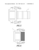
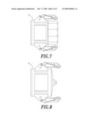
[0016]Therefore, by utilizing the characteristic capability of adapting a top casting-cavity insert and a bottom casting-cavity insert as desired, various types of hose couplings may be obtained as desired as shown in FIG. 3 to FIG. 8.
[0017]In comparison with conventional techniques, the method for manufacturing hose couplings provided by the present invention has the following advantages:
[0018]1. The invention provides a method for manufacturing hose couplings that can manufacture various types of hose couplings by adapting and replacing a top casting-cavity insert and a bottom casting-cavity insert as desired.
[0019]2. The invention provides a method for manufacturing hose couplings by utilizing a characteristic capability of adapting two casting-cavity inserts as desired to decrease the number of molds for use, so as to reduce the space occupied by the molds. Thus, the method is superior to that for manufacturing conventional couplings, in which different molds are needed for different types of couplings and, thus, more space can be used for storing different types of molds.
[0020]3. The invention provides a method for manufacturing hose couplings that may decrease the costs for making molds by decreasing the number of molds.
[0021]Many changes and modifications in the above described embodiment of the invention can, of course, be carried out without departing from the scope thereof. Accordingly, to promote the progress in science and the useful arts, the invention is disclosed and is intended to be limited only by the scope of the appended claims.
Claims:
1. A method for manufacturing hose couplings, making various types of top
casting-cavity inserts and bottom casting-cavity inserts adapted as
desired so as to give various types of hose couplings, the method
comprising steps:jointing and fixing a top casting-cavity insert and a
bottom casting-cavity insert within a mold base of a casting
machine;injecting a high-temperature molten metal from a furnace into
both the casting-cavity inserts, so that the molten metal can fill up the
casting-cavity inserts; andreleasing the solidified metal from the
casting-cavity inserts to form a hose coupling.
2. The method according claim 1, wherein the molten metal is injected through an automatic machine or manually into both the casting-cavity inserts.
3. The method according claim 1, wherein the molten metal is aluminum.
4. The method according claim 1, wherein the molten metal is copper.
5. The method according claim 1, wherein the molten metal is iron.
6. The method according claim 1, wherein the molten metal is steel.
7. A method for manufacturing hose couplings, making various types of top casting-cavity inserts and bottom casting-cavity inserts adapted as desired so as to give various types of hose couplings, the method comprising steps:jointing and fixing a top casting-cavity insert and a bottom casting-cavity insert within a mold base of a casting machine;injecting a high-temperature molten metal from a furnace into both the casting-cavity inserts, so that the molten metal can fill up the casting-cavity inserts;cooling both the casting-cavity inserts by using a cooling liquid, so that the molten metal within both the casting-cavity inserts can be cooled and solidified; releasing the solidified metal from the casting-cavity inserts to form a hose coupling.
8. The method according claim 7, wherein the molten metal is injected through an automatic machine or manually into both the casting-cavity inserts.
9. The method according claim 7, wherein the molten metal is aluminum.
10. The method according claim 7, wherein the molten metal is copper.
11. The method according claim 7, wherein the molten metal is iron.
12. The method according claim 7, wherein the molten metal is steel.
Description:
BACKGROUND OF THE INVENTION
[0001]1. Field of the invention
[0002]The present invention relates to a method for manufacturing hose couplings and, particularly, to a method for manufacturing hose couplings that can manufacture various types of hose couplings by utilizing a characteristic capability of adapting two casting-cavity inserts as desired.
[0003]2. Description of the Prior Art
[0004]Conventional manufacture of hose couplings mainly uses casting molds for performing the process of casting. However, there is a large variety of conventional types of hose couplings; therefore, various molds must be made as desired. Moreover, if some other types of couplings are required later, an increasing number of molds will be needed. All these molds not only take up a lot of space, but they also require much capital expenditure to finance the development of all these molds. Thus, the more molds required, the higher the relative cost is. This is, indeed, a burden to the manufacturer.
[0005]Since the conventional method has such drawbacks as described above, it is hardly a good one. An improvement is required urgently.
[0006]In view of the above difficulties associated with the conventional manufacture of hose couplings, the present inventor, through a long-term study and practice, has set about the work of improvement and innovation that provides the present method for manufacturing host couplings.
SUMMARY OF THE INVENTION
[0007]The primary aspect of the present invention is to provide a method for manufacturing hose couplings that can manufacture various types of hose couplings by adapting and replacing various top and bottom casting-cavity inserts as desired.
[0008]Another aspect of the present invention is to provide a method for manufacturing hose couplings by utilizing a characteristic capability of adapting two casting-cavity inserts as desired to decrease the number of molds required, so as to reduce the space needed to store the molds. The method is different from the conventional method, in which couplings are made with one mold for one type of coupling. As a result, with more molds being made, more space is used for storing the molds.
[0009]A method for manufacturing hose couplings to fulfill the aspects of the present invention comprises three steps. The first step involves jointing and fixing a top casting-cavity insert and a bottom casting-cavity insert within a mold base of a casting machine. The second step is injecting a high-temperature molten metal into both the casting-cavity inserts, so that the molten metal may flow to and fill up the cavities within the casting-cavity inserts. The third step is to cool the casting-cavity inserts by using a cooling liquid, so that the molten metal within the casting-cavity inserts may solidify to form a hose coupling after a cooling period. By using the method described above, various top casting-cavity inserts and bottom casting-cavity inserts may be adapted as desired and, therefore, various types of hose couplings may be manufactured by utilizing the characteristic capability of replacing two casting-cavity inserts as desired.
[0010]These features and advantages of the present invention will be fully understood and appreciated from the following detailed description of the accompanying Drawings.
BRIEF DESCRIPTION OF THE DRAWINGS
[0011]FIG. 1A and 1B are, respectively, schematic diagrams for the flow of manufacture and the product in one embodiment of the present invention.
[0012]FIG. 2A and 2B are, respectively, schematic diagrams for the flow of manufacture and the product in another one embodiment of the present invention.
[0013]FIG. 3-8 are schematic diagrams for other products according to the method for manufacturing hose couplings according to the present invention.
DESCRIPTION OF THE PREFERRED EMBODIMENT
[0014]Referring to FIG. 1A and 1B, which are, respectively, schematic diagrams for the flow of manufacture and the product in one embodiment of the method for manufacturing hose couplings according to the present invention, the method comprises the following steps: jointing and fixing a top casting-cavity insert 11 and a bottom casting-cavity insert 12 within a mold base of a casting machine; injecting a high-temperature molten metal from a furnace through an automatic machine or manually into both the casting-cavity inserts 11 and 12, so that the molten metal may fill up the cavities within the casting-cavity inserts 11 and 12, wherein the molten metal may be aluminum, copper, iron, steel or other metal; cooling the casting-cavity inserts 11 and 12 by using a cooling liquid, so that the molten metal within the casting-cavity inserts 11 and 12 may solidify; and taking the cooled and solidified metal from the casting-cavity inserts 11 and 12 to form a hose coupling 1, as shown in FIG. 1B. By using the method described above, a hose coupling according to the present invention may be obtained.
[0015]Referring to FIG. 2A and 2B, which are, respectively, schematic diagrams for the flow of manufacture and the product in another embodiment of the method for manufacturing hose couplings according to the present invention. Another top casting-cavity insert 13 is used to adapt to the original bottom casting-cavity insert 12 as shown in FIG. 2A and for manufacturing another type of hose coupling as shown in FIG. 2B. Alternatively, the original top casting-cavity insert 11 may be used to adapt to another bottom casting-cavity insert, for manufacturing another type of hose coupling. The flow of manufacture with respect to FIG. 2A and 2B is omitted herein since it is equivalent to that described above with respect to FIG. 1A and 1B.
[0016]Therefore, by utilizing the characteristic capability of adapting a top casting-cavity insert and a bottom casting-cavity insert as desired, various types of hose couplings may be obtained as desired as shown in FIG. 3 to FIG. 8.
[0017]In comparison with conventional techniques, the method for manufacturing hose couplings provided by the present invention has the following advantages:
[0018]1. The invention provides a method for manufacturing hose couplings that can manufacture various types of hose couplings by adapting and replacing a top casting-cavity insert and a bottom casting-cavity insert as desired.
[0019]2. The invention provides a method for manufacturing hose couplings by utilizing a characteristic capability of adapting two casting-cavity inserts as desired to decrease the number of molds for use, so as to reduce the space occupied by the molds. Thus, the method is superior to that for manufacturing conventional couplings, in which different molds are needed for different types of couplings and, thus, more space can be used for storing different types of molds.
[0020]3. The invention provides a method for manufacturing hose couplings that may decrease the costs for making molds by decreasing the number of molds.
[0021]Many changes and modifications in the above described embodiment of the invention can, of course, be carried out without departing from the scope thereof. Accordingly, to promote the progress in science and the useful arts, the invention is disclosed and is intended to be limited only by the scope of the appended claims.
User Contributions:
Comment about this patent or add new information about this topic:
| People who visited this patent also read: | |
| Patent application number | Title |
|---|---|
| 20130192283 | AIR-CONDITIONING APPARATUS |
| 20130192282 | VEHICLE AIR CONDITIONING SYSTEM |
| 20130192281 | Adsorption System |
| 20130192280 | REFRIGERATOR AND DEFROSTING METHOD THEREOF |
| 20130192279 | ICE MAKER FOR A REFRIGERATION APPLIANCE |
Images included with this patent application:
 |  |
 |  |
 |  |
| Similar patent applications: | |
| Date | Title |
|---|---|
| 2010-04-01 | Method for manufacturing a duplicating stamper |
| 2010-12-23 | Manufacturing method for composite alloy bonding wire |
| 2009-06-11 | Process of manufacturing power tool component |
| 2009-11-26 | Method and apparatus for manufacturing metal bars or ingots |
| 2012-04-26 | Method for manufacturing a sputtering target structure |
| New patent applications in this class: | |
| Date | Title |
|---|---|
| 2016-07-07 | Die casting apparatus and die casting method |
| 2016-06-23 | Center circular gating design for squeeze casting induction rotor core |
| 2016-06-16 | Die casting system and method |
| 2016-06-02 | Undercut die casting and injection molding systems and methods |
| 2016-04-28 | Chilled-zone microstructures for cast parts made with lightweight metal alloys |
| New patent applications from these inventors: | |
| Date | Title |
|---|---|
| 2012-02-23 | Tubular connection structure |
| 2010-06-03 | Structure for safety helmet |
| 2010-06-03 | Structure for safety helmet |
| Top Inventors for class "Metal founding" | |
| Rank | Inventor's name |
|---|---|
| 1 | Theodore A. Waniuk |
| 2 | Steven J. Bullied |
| 3 | Joseph C. Poole |
| 4 | Carl R. Verner |
| 5 | Christopher D. Prest |