Patent application title: SUPPLY AIR SYSTEM
Inventors:
Julius Itzrodt (Reutlingen, DE)
IPC8 Class: AF24F1100FI
USPC Class:
1 1
Class name:
Publication date: 2017-06-22
Patent application number: 20170176037
Abstract:
An apparatus and a method for controlling the same for conditioning an
air flow for an industrial installation, the apparatus having a cooling
medium circuit, a cooler incorporated into the cooling medium circuit and
having a cooling medium inlet and a cooling medium outlet, at least one
consumer incorporated into the cooling medium circuit and having a
cooling medium inlet and a cooling medium outlet, a supply air device for
conditioning air for the industrial installation, wherein the supply air
device has an air/cooling medium heat exchanger, an air inlet for feeding
air outside the industrial installation to the air/cooling medium heat
exchanger, an air outlet for feeding air from the air/cooling medium heat
exchanger to the industrial installation, a cooling medium inlet and a
cooling medium outlet.Claims:
1. An apparatus for conditioning an air flow for an industrial
installation, comprising: a) a cooling medium circuit, b) a cooler
incorporated into the cooling medium circuit and having a cooling medium
inlet and a cooling medium outlet, c) at least one consumer incorporated
into the cooling medium circuit and having a cooling medium inlet and a
cooling medium outlet, d) a supply air device for conditioning the air
flow, wherein the supply air device has an air/cooling medium heat
exchanger, an air inlet for feeding air outside the industrial
installation to the air/cooling medium heat exchanger, an air outlet for
feeding air from the air/cooling medium heat exchanger to the industrial
installation, a cooling medium inlet and a cooling medium outlet, wherein
e) the cooling medium outlet of the consumer can be connected to the
cooling medium inlet of the supply air device.
2. The apparatus according to claim 1, wherein the supply air device has a humidifier.
3. The apparatus according to claim 1, wherein the cooler is designed for operation without a free cooling unit.
4. The apparatus according to claim 1 further comprising a control system which is designed to establish a connection between the cooling medium outlet of the consumer and the cooling medium inlet of the supply air device if the temperature of the air supplied via the air inlet of the supply air device is below the temperature of the cooling medium at the cooling medium inlet of the supply air device.
5. A method for controlling an apparatus for conditioning an air flow for an industrial installation, wherein the apparatus comprises a cooling medium circuit having a cooler, at least one consumer incorporated into the cooling medium circuit and a supply air device, incorporated into the cooling medium circuit, for conditioning outside air for the industrial installation, the method comprising the steps of: determining the temperature of the outside air; and heating the outside air in the supply air device by means of the cooling medium downstream of the consumer if the temperature of the outside air falls below a threshold temperature.
6. The method according to claim 5, further comprising the step of: determining the temperature of the cooling medium downstream of the consumer, wherein the threshold temperature is the temperature of the cooling medium downstream of the consumer.
7. The method according to claim 1, further comprising the step of: comparing the outside air temperature and the cooling medium temperature.
8. The method according to claim 5, further comprising the step of: humidifying the outside air before heating the outside air.
9. The method according to claim 5, wherein heating the outside air causes cooling of the cooling medium, and the cooled cooling medium is fed to a further consumer.
Description:
RELATED APPLICATION
[0001] The present application claims priority to German Application No. 10 2015 016 330.2 filed Dec. 17, 2015--the contents of which are fully incorporated herein by reference.
BACKGROUND OF THE INVENTION
[0002] 1. Field of the Invention
[0003] The invention relates to an apparatus for conditioning an air flow for an industrial installation, having a cooling medium circuit, a cooler incorporated into the cooling medium circuit and having a cooling medium inlet and a cooling medium outlet, at least one consumer incorporated into the cooling medium circuit and having a cooling medium inlet and a cooling medium outlet, a supply air device for conditioning air for the industrial installation, wherein the supply air device has an air/cooling medium heat exchanger, an air inlet for feeding air outside the processing chamber to the air/cooling medium heat exchanger, an air outlet for feeding air from the air/cooling medium heat exchanger to the industrial installation, a cooling medium inlet and a cooling medium outlet.
[0004] Moreover, the invention relates to a method for controlling an apparatus for conditioning an air flow for an industrial installation.
[0005] 2. Description of the Prior Art
[0006] Such a combination of a cooler and a supply air device is often used in industrial installations for processing objects in a processing chamber. Such industrial installations can be a dryer, a warehouse or a coating plant for vehicle bodies or vehicle components, for example. In these locations, use is often made of a supply air device, which supplies individual sealed processing chambers or even the entire installation with conditioned outside air, for example. In this case, conditioning relates primarily to temperature control of the air to be supplied but also to humidification of the air. Depending on the location of the installation, it is accordingly necessary to cool outside air which is at a high temperature and to heat outside air which is at a low temperature, for example. At temperate latitudes, this means that the supply air device is in a cooling mode in summer and in a heating mode in winter.
[0007] Both processes--cooling and heating--are associated with a corresponding energy consumption. Depending on the design of the installation, the cooler can consume electric energy, for example, and the corresponding heating device can consume gas, for example.
[0008] To an increasing extent, consideration is being given, when designing such installations, not only to the one-off procurement costs but also to the overall energy consumption of such an installation. However, even in the case of existing installations, there is a need to minimize the overall energy consumption over a year of operation.
[0009] Thus, it is an object of the invention to specify an apparatus of the type stated at the outset and a corresponding method which enable investment costs and/or the average overall energy consumption to be reduced.
SUMMARY OF THE INVENTION
[0010] This object may be achieved by an apparatus for conditioning an air flow for an industrial installation, having a cooling medium circuit, a cooler incorporated into the cooling medium circuit and having a cooling medium inlet and a cooling medium outlet, at least one consumer incorporated into the cooling medium circuit and having a cooling medium inlet and a cooling medium outlet, a supply air device for conditioning the air flow, wherein the supply air device has an air/cooling medium heat exchanger, an air inlet for feeding air outside the industrial installation to the air/cooling medium heat exchanger, an air outlet for feeding air from the air/cooling medium heat exchanger to the industrial installation, a cooling medium inlet and a cooling medium outlet, wherein the cooling medium outlet of the consumer can be connected to the cooling medium inlet of the supply air device.
[0011] The apparatus according to the invention for conditioning an air flow for an industrial installation has a cooling medium circuit, a cooler, e.g. a refrigeration unit, incorporated into the cooling medium circuit and having a cooling medium inlet and a cooling medium outlet, at least one consumer incorporated into the cooling medium circuit and having a cooling medium inlet and a cooling medium outlet.
[0012] In the present case, an industrial installation is taken to be an area of an industrial installation, e.g. a workshop, spray booth or dryer, to be supplied with a conditioned, primarily temperature-controlled, air flow. This can be a space which is sealed off or can be sealed off, a space having air locks or a space having a constant or intermittent air flow. The object may also be to supply the area with the air flow only when required.
[0013] In the present case, a consumer is intended to mean a device which uses the cooling medium cooled by the cooler, while heating said medium, i.e. consumes it, as it were, in terms of energy. This can be a matter of individual appliances in the installation, a group of appliances in the installation, a single heat exchanger or even additional areas or spaces to be conditioned in an industrial installation, such as workshops, spray booths or similar.
[0014] A plurality of consumers can be connected in parallel or in series and may also be regarded as one consumer.
[0015] Moreover, the installation has a supply air device for conditioning air for an industrial installation. The supply air device has an air/cooling medium heat exchanger, an air duct with an air inlet for feeding air outside the industrial installation, that is to say, for example, outside air, to the air/cooling medium heat exchanger, and an air outlet for feeding air from the air/cooling medium heat exchanger to the industrial installation, and a cooling medium inlet and a cooling medium outlet.
[0016] According to the invention, it is envisaged that the cooling medium outlet of the consumer can be connected to the cooling medium inlet of the supply air device. Subject to certain conditions, therefore, the cooling medium consumed--i.e. heated--by the consumer can be fed to the supply air device. In the supply air device, heat transfer from the heated cooling medium to the air flow to be fed to the industrial installation can take place in the air/cooling medium heat exchanger. Once the consumer has transferred sufficient thermal energy to the cooling medium, this can be used by means of the supply air device to heat the air flow to be fed to the industrial installation. This can lead to a saving of the thermal energy that has to be made available to heat the air since, to a certain extent, waste heat from the consumer can be used to heat the air.
[0017] At the same time, the release of thermal energy from the cooling medium to the air flow brings about cooling of the cooling medium flowing through the supply air device. This reduces the cooling-medium cooling capacity that has to be provided by the cooler and represents a further energy saving.
[0018] In an advantageous embodiment, provision can be made for the supply air device to have a humidifier. Humidifying the supply air prior to heating enables the cooling medium to be cooled adiabatically through evaporation of the moisture supplied and thus allows a reduction in the cooling capacity that has to be provided by the cooler.
[0019] One embodiment of the installation envisages that the cooler is designed for operation without a free cooling unit. In the present case, a free cooling unit is understood to mean a device in which the cooling medium is cooled by air using the convection principle. A free cooling unit is generally situated outside a building. The air passed through the free cooling unit consists substantially of outside air and accordingly has an outside air temperature. By means of a free cooling unit, the cooling capacity to be provided by the cooler can be reduced since the cooling medium is pre-cooled by the free cooling unit. By virtue of the fact that the cooling medium outlet of the consumer can be connected to the cooling medium inlet of the supply air device, the supply air device can assume the function of a free cooling unit, which may therefore be obsolete or can be given correspondingly smaller dimensions.
[0020] A particularly preferred embodiment of the installation has a control system, which is designed to establish the connection between the cooling medium outlet of the consumer and the cooling medium inlet of the supply air device if the temperature of the air supplied via the air inlet of the supply air device is below the temperature of the cooling medium at the cooling medium inlet of the supply air device. Thus, as soon as there is a significant temperature difference, e.g. 1.5.degree. C., between the air supplied via the air inlet of the supply air device--that is to say, for example, the outside air--and the cooling medium temperature downstream of the consumer, the cooling medium can be cooled by means of the outside air or the air flow to be fed to the industrial installation can be heated.
[0021] Further embodiments of the invention are given in the dependent claims.
[0022] The object may furthermore be achieved by a method for controlling an apparatus for conditioning an air flow for an industrial installation. The apparatus comprises a cooling medium circuit having a cooler, at least one consumer incorporated into the cooling medium circuit and a supply air device, incorporated into the cooling medium circuit, for conditioning outside air for the industrial installation. The method comprises the following steps: determining the temperature of the outside air; and heating the outside air in the supply air device by means of the cooling medium downstream of the consumer if the temperature of the outside air falls below a threshold temperature. Thus, as soon as the temperature of the outside air is low enough, it is heated by means of the cooling medium, or the cooling medium is cooled by the outside air. In this way, the above-explained advantages of an energy saving in heating the outside air or in the necessary cooling of the cooling medium are obtained.
[0023] A development of the method envisages that the method additionally comprises the step of determining the temperature of the cooling medium downstream of the consumer. The temperature of the cooling medium downstream of the consumer thus represents the threshold temperature. Thus, as soon as the temperature of the outside air has fallen below the temperature of the cooling medium downstream of the consumer or there is a sufficiently large temperature difference between the two temperatures, the outside air can be heated by means of the cooling medium and the cooling medium can be cooled by means of the outside air.
[0024] In an advantageous development of the method, it is envisaged that the outside air is humidified before being heated.
[0025] In a particularly preferred embodiment of the method, heating the outside air causes cooling of the cooling medium, and the cooled cooling medium is fed to a further consumer.
[0026] Thus, the cooling medium cooled by the supply air device can be fed directly to a further consumer, such as a cooling zone or a spray booth.
[0027] Further embodiments of the method are given in the dependent method claims.
[0028] Other advantages and aspects of the present invention will become apparent upon reading the following description of the drawings and detailed description of the invention.
BRIEF DESCRIPTION OF THE DRAWINGS
[0029] Illustrative embodiments of the invention are explained in greater detail below with reference to the drawings, in which:
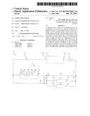
[0030] FIG. 1 shows a schematic illustration of an apparatus according to the invention for conditioning an air flow for an industrial installation;
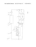
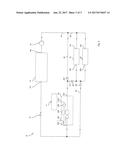
[0031] FIG. 2 shows a first switching state of the apparatus in FIG. 1; and
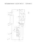
[0032] FIG. 3 shows a second switching state of the apparatus in FIG. 1.
DESCRIPTION OF PREFERRED ILLUSTRATIVE EMBODIMENTS
[0033] While this invention is susceptible to embodiments in many different forms, there is described in detail herein, preferred embodiments of the invention with the understanding that the present disclosures are to be considered as exemplifications of the principles of the invention and are not intended to limit the broad aspects of the invention to the embodiments illustrated.
[0034] FIG. 1 shows a schematic illustration of an apparatus 10 for conditioning an air flow for an industrial installation. The industrial installation can form a processing chamber 11, for example, which is illustrated only schematically and can be a drying chamber, a cooling zone, a spray booth or the like, for example, or, alternatively, can be constructed from a plurality of processing chambers.
[0035] The apparatus 10 has a cooling medium circuit 12, the flow direction of which is indicated by arrows. In the present case, water is used as the cooling medium. Of course, it is also possible to use other cooling media.
[0036] A cooler 14, e.g. a cooling appliance, is incorporated into the cooling medium circuit 12. The cooler 14 can be equipped, as an independent unit, with a dedicated refrigerating circuit, comprising a condenser, evaporator, compressor and expansion valve, for example. The cooler 14 comprises a cooling medium inlet 141 and a cooling medium outlet 142. The cooler 14 is designed, by means of electric energy for example, to cool the cooling medium flowing into the cooling medium inlet 141 and to discharge it again in a cooled state at the cooling medium outlet 142. Possible temperatures of the cooling medium are in a range of 10-22.degree. C., typically 12-16.degree. C. at the cooling medium inlet 141, and in a range of 6-16.degree. C., typically 6-10.degree. C., at the cooling medium outlet and a typical ratio of the inlet temperature to the outlet temperature could be 12/6, 15/7 or 16/10, for example.
[0037] The cooling medium circuit 12 is maintained by means of a pump 16.
[0038] Likewise incorporated into the cooling medium circuit 12 in the embodiment shown in FIG. 1 are a first consumer 18 and a second consumer 20. The first and second consumers 18, 20 each have a cooling medium inlet 181, 201 and a cooling medium outlet 182, 202. In the embodiment shown in FIG. 1, the two consumers 18, 20 are connected in parallel. Of course, serial connection of the two consumers 18, 20, just one consumer or a larger number of consumers would also be conceivable.
[0039] Likewise incorporated into the cooling medium circuit 12 is a supply air device 22 having a cooling medium inlet 221 and a cooling medium outlet 222. Moreover, the supply air device 22 has an air inlet 223 and an air outlet 224. Via the air inlet 223, the supply air device 22 can draw in air from outside the processing chamber 11 by means of a blower 226 and discharge it to the processing chamber 11 via the air outlet 224. Moreover, the supply air device 22 has an air/cooling medium heat exchanger 225 and, optionally, a secondary pump 227 for the cooling medium. The air/cooling medium heat exchanger 225 is connected both to the cooling medium circuit 12 and to the air duct feeding air to the processing chamber 11 and allows heat transfer from the cooling medium to the air or vice versa, depending on the temperature conditions. Both the cooling medium outlet 222 of the supply air device 22 and the cooling medium outlets 182, 202 of the consumers 18, 20 are connected to the cooling medium inlet 141 of the cooler 14.
[0040] In order to adapt the installation 10 during operation to the prevailing temperature conditions, in particular to the temperature of the air at the air inlet 223, various control valves and lines are provided for the cooling medium. A line 24 leading from the pump 16 to the consumers 18, 20 and to the supply air device 22 divides into a line 26, which extends parallel to the consumers 18, 20, and a line 28, which supplies the consumers 18, 20. The outlet of the consumers 18, 20 is connected to the cooling medium inlet 141 by a line 30, which extends parallel to the supply air device 22. At the same time, the outlet of the consumers 18, 20 is connected to the cooling medium inlet 221 of the supply air device 22 by a line 32.
[0041] Respective control valves are arranged in lines 26, 30, 32. In the open state, the control valve 261 arranged in line 26 makes it possible to connect the supply air device 22 in parallel with the consumers 18, 20 and thus to distribute the cooling medium delivered from the cooler 14 via line 24 to the consumers 18, 20 and the supply air device 22. In the closed state of control valve 261, the supply air device 22 can only be supplied with cooling medium via the cooling medium outlets 182, 202 of the consumers 18, 20 and line 32.
[0042] In the open state, the control valve 301 arranged in line 30 allows the cooling medium consumed by the consumers 18, 20 to be discharged directly to the cooler 14. In the closed state of control valve 301, the consumed cooling medium can only be delivered to the supply air device 22 via line 32.
[0043] In the closed state, the control valve 321 arranged in line 32 prevents a transfer of cooling medium whose energy has not been consumed directly into the cooler 14 from line 26 via lines 32, 30.
[0044] Various operating states of the installation 10 will now be explained with reference to FIGS. 2 and 3, which show various switching states of the installation 10 in FIG. 1.
[0045] FIG. 2 shows a first switching state of the installation 10, in which control valves 261, 301 are open and control valve 321 is closed. In this switching state, the consumers 18, 20 and the supply air device 22 are connected in parallel. This means that the cooling medium delivered from the cooler 14 via line 24 is distributed between the supply air device 22 and the consumers 18, 20. The cooling medium outlets 222, 182, 202 of the supply air device 22 and of the consumers 18, 20 are each connected by corresponding lines to the cooling medium inlet 141 of the cooler 14.
[0046] This switching state is adopted when the outside air drawn in via the air inlet 223 of the supply air device 22 has a higher temperature than the cooling medium at the cooling medium outlets 182, 202 of the consumers 18, 20. In this case, it is generally indicated to cool the outside air drawn in to a desired temperature. For this purpose, heat transfer takes place from the cooling medium flowing into the air/cooling medium heat exchanger 225 via the cooling medium inlet 221 of the supply air device 22 to the outside air flowing through the air/cooling medium heat exchanger 225. In this operating state, there is no recovery of the increase in the temperature of the cooling medium produced by the consumers 18, 20. This mode of operation can also be referred to as a summer operating state.
[0047] This mode of operation is generally also adopted when the temperature of the outside air, although above the return temperature of the cooling medium, is still so low that it does not yet require cooling but may even require heating.
[0048] FIG. 3 shows a second switching state of the installation 10, in which the control valves 261, 301 are closed and control valve 321 is open. The consumers 18, 20, on the one hand, and the supply air device 22, on the other hand, are now in a serial configuration. The cooling medium delivered by the pump 16 via line 24 first of all flows through the consumers 18, 20, where it undergoes a temperature increase. The cooling medium leaving the cooling medium outlets 182, 202 passes via line 32 to the cooling medium inlet 221 of the supply air device 22 and then flows through the air/cooling medium heat exchanger 225. There, the heated cooling medium can release thermal energy to the air which is drawn in via the air inlet 223 and is discharged, for example, to the processing chamber 11 via the air outlet 224. Since the pressure drop across the overall system is increased in the case of serial connection of the consumers 18, 20, on the one hand, and of the supply air device 22, on the other hand, the secondary pump 227 can be switched on in this case or can operate with an increased volume flow and/or delivery pressure. This compensation allows a constant effective total pressure drop across the consumers and the supply air device.
[0049] This operating state is chosen if the temperature of the air which is drawn in via the air inlet 223--that is to say, in this case, the outside air--is below the temperature of the cooling medium at the cooling medium outlets 182, 202. The cooling medium cooled in this way can be passed to other consumers of the installation 10 in order to be used there, for example, in a cooling zone or in a spray booth for process cooling. As an alternative, the cooled cooling medium can be passed to the cooler 14, as shown in FIG. 3, and thus reduce the energy consumption thereof. This mode of operation can also be referred to as a winter operating state.
[0050] If the temperature of the outside air is -9.degree. C., for example, and the cooling medium circuit 12 is designed for a feed temperature of 10.degree. C. in line 142 and a return temperature of 16.degree. C. in line 141, the temperature of the air after the air/cooling medium heat exchanger 225 is 5.degree. C. In order to bring the air to be fed to the processing chamber 11 to the required temperature of 20.degree. C., it is heated to 18.degree. C. by means of an additional heating device so as to be blown into the processing chamber 11 by the blower 226 at 20.degree. C. after compression. At a typical air throughput of 86,000 m.sup.3/h, this can mean a recovered cooling capacity of, for example, 400 kW at the air/cooling medium heat exchanger 225 and a saved heating capacity of about 400 kW at the heating device. A correspondingly smaller heating capacity of the heating device can therefore be chosen and a free cooler can be dispensed with, resulting in lower investment costs.
[0051] On the one hand, this reduces the energy consumption of the cooler 14. On the other hand, less energy or no energy has to be used to heat the air to be fed to the processing chamber 11. On the one hand, this renders obsolete an additional free cooling system, which is otherwise associated with the cooler 14, and thus reduces costs of investment into the installation 10. On the other hand, the annual energy consumption of the overall installation is reduced by saving energy for heating the outside air. At the same time, retrofitting of existing installations with relatively little outlay is possible--essentially comprising installing control valves 261, 321, 301, if appropriate a secondary pump 227 and the additional line 32.
[0052] In the original design of such an installation 10, the cooling medium circuit overall can be designed for higher temperatures, for example. This leads to larger savings since the "winter" operating state in FIG. 3 can be used in a larger proportion of the year. Moreover, it may be advantageous to arrange the supply air device 22 in the vicinity of the cooler 14, thus enabling the entire return of the cooling medium circuit 12 to be used by the supply device 22 at the highest possible temperature. Overall, the savings effect is all the greater, the lower the average annual temperature of the outside air at the location where the installation 10 is sited.
[0053] While in the foregoing there has been set forth various embodiments of the invention, it is to be understood that the present invention may be embodied in other specific forms without departing from the spirit or central characteristics thereof. The present embodiments, therefore, are to be considered in all respects as illustrative and not restrictive, and the invention is not to be limited to the details given herein. While specific embodiments have been illustrated and described, numerous modifications come to mind without significantly departing from the characteristics of the invention and the scope of protection is only limited by the scope of the accompanying claims.
User Contributions:
Comment about this patent or add new information about this topic:
Images included with this patent application:
 |  |
 |  |
| New patent applications in this class: | |
| Date | Title |
|---|---|
| 2022-09-22 | Electronic device |
| 2022-09-22 | Front-facing proximity detection using capacitive sensor |
| 2022-09-22 | Touch-control panel and touch-control display apparatus |
| 2022-09-22 | Sensing circuit with signal compensation |
| 2022-09-22 | Reduced-size interfaces for managing alerts |